Symphony Acoustics, Inc. 103 Rio Rancho Dr. NE Ste. B-4, Rio Rancho, NM ... (MEMS) accelerometers were fabricated and studied by Waters et al.[7] Tunable ...
MEMS and Optoelectronics Integration for Physical Sensors
Dustin W. Carr Symphony Acoustics, Inc. 103 Rio Rancho Dr. NE Ste. B-4, Rio Rancho, NM 87124 Abstract We discuss the use of laser of interferometric techniques as motion transducers to be used in acoustics and vibration sensing. This includes a review of the basic concepts, and addresses some of the strengths and challenges associated with this approach. Results from prototype lab devices based upon Fabry-Perot interferometers are presented. The use of laser interferometry in physical sensors has long been considered, if not heralded, as a viable means for sensor performance enhancement. The basic principal involves the creation of an optical path whose length is varied when subjected to an external stimulus, such as pressure or acceleration. Many different optical designs have been proposed that all accomplish the same goal of translating this path length change into an amplitude change at a photodector through interference or diffraction. Microphones and accelerometers are two types of sensors that generally rely upon the detection of miniscule motions in a small object. Some of the earliest work describing these sorts of applications for interferometry can be found in the patent literature, wherein generic forms of accelerometers and microphones have been proposed, based on upon Michelson or Fabry-perot type interferometers [1,2]. Work by Greywall [3] looked at specific implementations using simple silicon-nitride designs and was the first to consider the possibility of placing all of the components in a small package. Transducers based on grating light valves [4] were explored by Degertekin et al [5,6]. Fabry-perot based micro-electromechanical system (MEMS) accelerometers were fabricated and studied by Waters et al.[7] Tunable Fresnel lens structures have been made with considerable success at SINTEF by Sagberg et al. [8] Work by Carr et al. studied a different type of lateral-motion grating transduction [9,10]. All of this work has trumpeted the potential of the optical transducer, but few have actually produced sensors that approach this potential, or ones that even compete well with existing commercial off the shelf (COTS) devices based on other transduction techniques. This does not necessarily take away from the potential of the different approaches, but does highlight the need to contain exuberant support of the technology and perform a more careful study of the benefits as they apply to specific applications. In this paper, we will review the fundamental physics and optics that are generally applicable to all such interference devices, followed by the consideration of two specific test cases: an accelerometer and a microphone. A Fabry-Perot type of interferometer can be used for consideration of the design issues in these types of transducers in general. This type of interferometer has two parallel dielectric mirrors that bound an empty cavity as shown in Fig. 1. Light that is incident upon the cavity will be partially reflected according to the relation
R=
1
(1 + F sin2 ϕ 2 )
2
(1)
wherein F is determined by the reflectance of the two mirrors
F =
4R0 ( 1 − R0 )2
(2)
This assumes that the reflectance values of the two mirrors are equal. ϕ=4pd/l is the phase that is picked up in a wave with wavelength l as it makes a roundtrip within the cavity of length d. . Figure 1 shows a typical response for a cavity whose mirrors have a moderate reflectance. From this plot, we see that the slope has a maximum value at the points indicated. The slope sensitivity of the transducer is the change in optical power at the detector per unit change in cavity length. The maximum slope can be shown to be
Optical Response of a Fabry−Perot Cavity
1
Reflected Transmitted
0.9
Optical Signal (R+T=1)
0.8 0.7
Maximum Sensitivity
Incident E0
0.6 0.5
d
0.4 0.3 0.2 0.1 0 60.2
60.25
60.3
60.35
60.4 60.45 60.5 60.55 Cavity Thickness ( µm)
60.6
60.65
60.7
Figure 1. The optical response of a Fabry-Perot cavity as the the length is varied. The inset demonstrates how multiple reflections within the cavity produce beams of various phases. When all of the transmitted beams add up in-phase, the cavity is on resonance and will produce a transmittance pak as shown. In our current approach, we operate at the point of maximum sensitivity as shown.
S max =
Iπ W F −1 λ m
(3)
where I is the optical power. From this we can start to see some of the potential benefit of the optical transducer. For illustration, a cavity with a reflectance of 0.7 on each side and an operating wavelength of 850 nm can achieve a relative sensitivity of 2%/nm. If we only consider laser relative intensity noise as the limit, we can still achieve a transducer noise floor that is below 1 pm/Hz1/2 for a laser with a readily achievable intensity noise of -100 dB/Hz. Theoretically, the true physical limit is going to be the photodiode shot noise. While challenging in practice, there are certainly designs that enable this limit to be approached. For instance, a differential detector can be designed that captures the reflected and transmitted signals, wherein the laser intensity noise is common to both and can thus be subtracted out. More advanced electronics techniques have been developed that enable automatic balancing of these signals, leading to up to 60 dB of additional intensity noise cancellation [11]. These approaches have been shown to yield systems that are within 2 dB of the shot noise limit. The photodiode shot noise is given by the relation
nshot =
2eIB
A Hz 1/ 2
(4)
where e is the electron charge, I is the optical power that is incident upon the photodiode, and B is the photodiode sensitivity in units of Amperes/Watt. Dividing this by the slope sensitivity, we can arrive at an expression for the displacement noise limit.
ηshot =
λ π
2e
m
IB ( F − 1 ) Hz 1/ 2
(5)
As an example, for a 1 mW laser at wavelength 850 nm, a photodiode sensitivity of 0.5, and cavity mirror reflectances of 0.7, this results in a theoretical shot noise limit of 1.25 fm/Hz1/2. In practical designs, there are unfortunately additional sources of noise that are not necessarily common between the reflected and transmitted signals. In particular, shifts in the laser wavelength produce a signal that is not discernible from a shift in the cavity length. This wavelength noise is depends upon the cavity length, and so a shorter cavity results in a lower impact on the effective noise. To be exact, if we have a known wavelength noise spectral density in units of m/Hz1/2, then this will result in an equivalent displacement noise of:
ηλ = δλ
d m λ Hz 1/ 2
(6)
Other design considerations, however, prevent this cavity from becoming arbitrarily short. A practical range would be somewhere between 10 and 100 μm. In order to achieve a noise level that is equivalent to the shot noise limit, the laser wavelength must be maintained to better than 1 part in 109 per root Hz. While this is achievable in COTS diode lasers, it requires very careful design of the laser current control electronics. Given that the laser diodes have been optimized for applications that do not have this constraint, there is very little information on wavelength noise for COTS devices. Another type of wavelength noise arises in multi-mode diode lasers. These lasers have more than one longitudinal mode, with each mode having slightly different wavelength. These lasers can actually have a good value of relative intensity noise, but when used in an interferometric setting, mode-hopping effects can easily dominate the noise. These sudden stochastic hops between modes can produce substantial changes in the amplitude output from the transducer. Even the appearance of modes that are 40 dB below the primary mode can be problematic if the system is not designed properly. Many papers could be written on this particular design issue, but suffice it to say that it is important to utilize single-mode lasers in conjunction with laser control electronics that can mitigate these effects. Note that laser wavelength noise is not related directly to the laser linewidth. The latter merely determines the coherence length of the laser, which is the distance that a wave packet can travel without the constituent waves falling out phase. A shorter coherence length can result in a reduced signal amplitude in a transducer, but for cavity lengths around or below 100 μm, this is not a significant issue when quality laser diodes are utilized. Optical interference transducers have other mechanical advantages over their counterparts that use capacitive, piezoresistive, or piezoelectric sensing. First and foremost, the sensing mechanism is decoupled from the mechanical elements. Effectively, the motion of the structure being measured is “remote sensed”. An optical spot size that is as small as 10 μm can be used to interrogate the position. In other approaches, this is not typically the case. For instance, in a capacitive sensed device, the sensitivity will scale with the area of the electrodes, the distance between electrodes, and an applied voltage. The applied voltage in turn produces a force that must be accounted for in the design. All of these factors must be considered together in order to create an optimum design. The challenge in the optical design is that the response is only linear over a distance that is less than a quarter wavelength. There are many approaches for overcoming this limitation. The use of electrostatic actuators to compensate and pull the device to an optimum operating point has been proposed repeatedly. This approach introduces challenges that greatly reduce the potential benefits of the optical design when compared with other approaches. Introducing these actuators increases the complexity of the fabrication process, restricts the mechanical design space, and most importantly, creates a potential nightmare from a reliability standpoint. Laser wavelength can also be used as a control parameter, as a typical laser diode will have a wavelength that varies with the laser current. This is a most desirable design, as it allows the signal sensitivity to be directly controlled through the electronics. It does, however, require that the cavity length be sufficiently large (>50μm). The ability to dynamically modify the sensitivity in the optical domain can lead to more advanced signal processing solutions for noise mitigation. Simply considering the signal to noise is not nearly sufficient for justifying the use of optical interference transducers. As shown above, there are many design considerations. In truth, there is nothing that is intrinsically more sensitive or lower noise in an optical transducer than can be typically had in conventional transducers. Only when taken as part of a complete sensor system design can the actual benefits be discerned. To that end, we consider how these transducers factor into the design of two test cases. A condenser microphone senses sound pressure fluctuations by observing the motion of a diaphragm that separates the incident medium from a reservoir of air with constant pressure. Conventional microphones sense the motion by applying a voltage between the diaphragm and an underlying electrode. In an electret condenser micro-
phone, this voltage is induced by charge that is stored on a dielectric. As mentioned above, the performance of this type of device depends strongly upon the electrode area, the electrode gap, and the amount of charge stored on the dielectric. In addition, the electrode design not only impacts the signal level, but actually affects the mechanical noise. A thorough description of mechanical thermal noise is given by Gabrielson [12], and specific considerations for miniature electret condenser microphones by Thompson et al.[13] The main issues to consider in regards to the design are sources of air flow resistance that lead to thermal noise fluctuations in the pressure at the inputs. Optimized designs for high performance microphones are limited by this thermal noise. Adding a new type of transducer without changing the mechanical design will thus merely enable the more precise sensing of this mechanical noise, but it certainly will not change the equivalent input noise of the microphone. The optical transducer can alleviate some of the design limitations that determine this thermal noise. We are no longer restricted to having a minimal gap behind our diaphragm. The spacing between the diaphragm and the cavity mirror can be made much larger than is typically seen in a condenser microphone. Furthermore, we can reduce the overall size of the device. Reducing the membrane size can result in a higher stiffness, but since the optical transducer can improve upon the displacement signal to noise, an increased stiffness can be tolerated. Size reduction is generally desirable from an application standpoint, but can also lead to a reduced thermal noise thanks to a reduction in the input resistance.
Lid chip carrier with photodiodes
Silicon substrate with patterned diaphragm membranes Fixed mirrors Alloy structural elements. Collimating Lenses
Base chip carrier with VCSELs and photodiodes
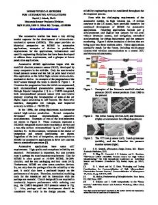
Figure 2. (above) Exploded mechanical drawing of the constiuent parts in the Symphony Acoustics SA1000 dual microphone prototype. Figure 3. (right) Photograph of a completed assembly, with a U.S. dime and quarter for size comparison. The size of the device is currently limited by our manual assembly techniques. The actual microphone diaphragm is only 2 mm square.
Our prototype implementation of an optical microphone utilizes an optical cavity similar to the Fabry-Perot example that we have been discussing. This prototype has two 2mm diaphragm microphones built into the package, with a spacing of 6 mm. This pair of microphones enables us to study the benefits of our approach for directional sensing, but for this paper we will focus only on the performance of a single microphone. The device is shown in figures 2 and 3. The noise spectrum in an isolation chamber after being calibrated to a B&K 4189 measurement microphone is shown in Figure 4. The spectrum when the system is under vacuum, and thus not subject to acoustic thermal noise, is also shown. The approximate equivalent input noise of the device in air is 23 dBA +/- 1 dB, very good for a device of this size. The peak signal level has been measured to be above 120 dB with total harmonic distortion below 0.1%. −20
Noise Spectrum of Symphony Acoustics’ Prototype compared with B&K 4189
−75 B&K 4189 SA1000
Vacuum 1 Atm.
−80 Measured signal calibrated to 1 Pa at 0 dB
−40 Sound Pressure Level (dBV re 1 V/Pa)
Noise Spectrum at Atmosphere and Vacuum
−60
−80
−100
−120
−85
Vacuum thermal noise peak
−90 −95 −100 −105 −110 −115 −120
−140 1 10
10
2
3
10 Frequency (Hz)
10
4
10
5
−125 1 10
10
2
3
10 Frequency (Hz)
10
4
10
5
Figure 4. Left is shown a plot used for calibration of the SA1000 prototype. This is an FFT power spectral density plot. A 50 Hz signal was applied from a subwoofer, and the response measured simultaneously from the B&K 4189 measurement microphone and the SA1000. On the right is shown the response of the device at atmosphere and vacuum, indicating that acoustic thermal noise dominates the noise performance at atmosphere. The comparison between air and vacuum performance indicates that the device is thermal noise limited at atmospheric pressure. The transducer noise under vacuum is 9 dB lower. The mechanical design was not optimized in this prototype implementation. Better design of the input port as well as the back cavity should lead to noise performance that is limited by the transducer noise, or less than 15 dBA. In an accelerometer, the issues are somewhat different. These devices sense the motion of a proof mass that is attached to a spring. For high performance accelerometers – such as are used in inertial navigation systems, seismology, and oil exploration – thermal noise is still a dominant concern. However, since airflow is restricted in an accelerometer package, there is no acoustic thermal noise. All of the thermal noise can be expressed in terms of design parameters in the system. The key mechanical parameters for any accelerometer device are the fundamental resonant frequency, the mass, and the quality factor, or Q, of the resonance. A good accelerometer will not have any resonances that are near the fundamental. The square of the resonant frequency is the scale factor between the applied acceleration and the proof mass displacement . The Q is determined by mechanical resistance, which then determines the thermal noise force that is applied to the accelerometer. The resulting acceleration noise has a white spectrum below the resonant frequency, with amplitude:
ηT =
4kbT ω0 m mQ s 2Hz 1 2
(7)
The shot noise limit is once again the fundamental physical limit for the optical transducer. Following the process above, this can be expressed in terms of acceleration:
ηshot =
λω02 π
2e
m
BI 0 ( F − 1 ) s 2Hz 12
(8)
10
Contour Plot of Noise Floor in dB rel to 1 g/Hz1/2 intensity = 10 mw, F = 10, Q = 100
4
40
50
−1
−1 1
−1 2
0
0
−1 30
−140
0
−1
−16
2
0
0
−1 6
−1 5
0
0
−1 7
−1 4
−1 2
0
−1 3
0
10
10
−5
10
−4
−1 8
60
1
10 −6 10
−1
−1
50
−1
−1
70
40
−1 3
0
0
Resonant Frequency (Hz)
10
3
−3
10 Mass (grams)
10
−2
10
−1
10
0
Figure 5. A contour plot of the total noise floor when the shot noise limit and the mechanical thermal noise limit are considered. The key design parameters are the mass and the resonant frequency of the spring-mass system. The green area denotes the range of parameters where the device is limited by mechanical thermal noise.
Figure 5 shows the noise floor contours as the resonant frequency and the proof mass are varied, assuming typical values for the design parameters as shown. The sensing modalities used currently are similar to microphones: capacitive, piezoresistive, and piezoelectric. For geophones, electromagnetic sensors are also used, which actually detect velocity of a moving proof mass by sensing induced current when the magnetic mass moves through a coil. As with microphones, the transduction mechanism figures strongly into the mechanics of the system. The strength of the optical technique is in the ability to decouple the mechanics and the transducer. The small size and cost of the optical transducer also enables more than one to be placed in a package, providing means for drift reduction and signal enhancement. Materials choice is also more flexible with the optical technique. The spring mass system is a passive device that requires no electrical connections. It is therefore possible to choose materials with very good thermal and mechanical properties without being constrained to using silicon or quartz crystal structures as are commonly found in high-end accelerometer systems. A simple prototype system was built using similar parts as for the microphone described above, but replaced the membrane structure with a cantilever spring-mass with a mirror attached. Figure 6 shows some initial results from this prototype. This plot demonstrates the concepts of wavelength tuning for sensitivity control. The signals from the reflected and transmitted photodiodes are shown, while the laser current is being swept. The increase in current results in higher laser power (about 1 mW peak in this sweep) while also increasing the laser wavelength by about 2 nm over this range. As a result, the cavity resonance as a function of wavelength can be seen. The device was rotated through 180 degrees in the lab, providing measurements at 1 g, 0 g, and -1 g. The resonant frequency of the device is about 1 kHz, and so the deflection of the proof mass is approximate 250 nm at 1 g, which is slightly larger than the linear operating range of the device if operated in an open loop. It should be clear, however, that using the laser current to create a closed-loop measurement can result in a substantially larger dynamic range. At the point of maximum sensitivity on this curve, we have measured a noise floor of 300 nV/Hz1/2 in the differential signal at 1 kHz. The sensitivity is approximately 1 V/g. The noise floor is determined by laser wavelength noise in this implementation, but improvements in the optical design could greatly reduce that.
Figure 6. In this plot, a sawtooth signal has been applied on the laser current. We show the detected signals from the reflected and transmitted photodiodes as well as the sum of the two, for three different values of acceleration. The saturation is due to the 3.3V supply rail used in the transimpedance amplifiers. Note that slight misalignment of the optics results in a non-optimal response where the transmittance on resonance is only 50%. In conclusion, the current state of optics and MEMS technology has matured to the point where it is possible to realize the promise of interferometric sensors. Simply having a better transducer, however, is insufficient for making devices that can be successful in field applications. When the entire sensor system design is taken into consideration, it is possible for real benefits to be found by switching to optical technology. Symphony Acoustics has shown this to be the case, as we have built quality devices from readily available components using rudimentary assembly techniques.
References: 1. Uda, Kazutaka. Pressure Sensitive Element. U. S. Pat. No. 4,682,500 (1987). 2. Haritonidis, Joseph H.; Senturia, Stephen D.; Warkentin, David J.; Mehregany, Mehran; Optical Micropressure Transducer. U. S. Pat. No. 4,926,696 (1990). 3. Greywall, D. S. Micromachined Optical Interference Microphone Sens. Actuators. Vol. 75, pp. 257-268, 1999 4. Solgard, O.; Sandejas F. S. A.; Boom D. M. Deformable Grating Optical Modulator. Opt. Lett. Vol. 17 pp. 688690, 1992. 5. Lee, Wook; Hall, Neal A.; Zhou, Zhiping; Degertekin, F. Levent. Fabrication and Characterization of a Micromachined Acoustic Sensor With Integrated Optical Readout. J. Sel. Topics. Quantum Electron. Vol. 10 pp. 643-651, 2004. 6. Hall, Neal A.; Bicen, Baris; Jeelani, M. Kamran; Lee Wook; Qureshi, Shakeel; Degertekin F. Levent; Okandan, Murat. Micromachined microphones with diffraction-based optical displacement detection. J. Acoustical. Soc.
7. 8. 9. 10. 11. 12. 13.
Amer. Vol 118, pp. 3000-3009, 2005. Waters, Richard L.; Aklufi Monti E. Micromachined Fabry-Perot Interferometer for motion detection. Appl. Phys. Let. Vol. 81 pp. 3320-3322, 2002. Sagberg, Hakon; Sudbo, Aasmund; Solgaard Olav; Bakke, Kari Anne Hestens; Johansen Ib-Rune; Optical Microphone Based on a Modulated Diffractive Lens. IEEE Phot. Tech. Let. Vol 15 pp. 1431-1433, 2003. Carr, D. W.; Sullivan, J. P.; Friedmann, T. A.; Laterally Deformable nanomechanical zero-order gratings: Anomalous diffraction studied by rigorous coupled wave analysis. Opt. Lett. Vol. 28, pp. 1636-1638, 2003. Keeler, B. E. N., Carr, D. W.; Sullivan , J. P.; Friedmann, T. A.; Wendt, J. R. Experimental demonstration of a laterally deformable optical NEMS grating transducer. Opt. Lett. Vol. 29 pp. 1182-84, 2004. Hobbs, Philip C. D. Ultrasensitive laser measurements without tears. Appl. Opt. Vol. 36 pp. 903-920, 1997. Gabrielson, Thomas B. Mechanical-Thermal Noise in Micromachined Acoustics and Vibration Sensors. IEEE Trans. Electron. Dev. Vol. 40, pp. 903-909. Thompson, Stephen C.; LoPresti, Janice L.; Ring, Eugene M.; Nepomuceno, Henry G.; Beard, John J.; Ballad, William J.; Carlson, Elmer V. Noise in miniature microphones. J. Acoust. Soc. Am. Vol 111 pp. 861-866, 2002.