Department of Veterans Affairs Journal of Rehabilitation Research and Development Vol . 34 No . 2, April 1997 Pages 162-170
Methods for determining three-dimensional wheelchair pushrim forces and moments : A technical note Rory A. Cooper, PhD ; Rick N. Robertson, PhD ; David P. VanSickle, MS ; Michael L . Boninger, MD; Sean D. Shimada, MS Human Engineering Research Laboratories, Departments of Rehabilitation Science and Technology, Mechanical Engineering, and Bioengineering University of Pittsburgh, Pittsburgh, PA 15261 ; Division of Physical Medicine and Rehabilitation, Department of Orthopaedic Surgery, University of Pittsburgh Medical Center, Pittsburgh, PA 15261; Research Service, Highland Drive VA Medical Center, Pittsburgh, PA 15206
Abstract This technical note illustrates that some of the differences that have been reported regarding wheelchair propulsion may be due to the methods used to calculate key variables. Wheelchair ambulation is a very important form of locomotion that lacks a standard pushrim force and moment analysis system . We have developed tools for analyzing upper limb biomechanics during manual wheelchair propulsion . Among the tools is a system that allows the direct measurement of global coordinate forces FX , F y , F, and corresponding moments . The analytical techniques presented here allow calculation of radial (F r) and tangential (Fr) forces, the determination of point of force application (PFA), and the moment applied by the hand (M h,). Our results show that the PFA can be calculated from kinetic data . Comparison of the PFA to the second metacarpophalangeal (MP) joint, calculated from kinematic data and used in previous studies, resulted in a 0 .2 radian difference on average, with the PFA showing greater variation near the beginning and ending of the propulsion phase . Analysis of methods for calculating the applied tangential force showed that using the PFA provides a more accurate measurement of this force than the previous method of assuming negligible hand-moment contribution . The hand moment was compared using the calculated
PFA and assuming the PFA was coincident with the second MP joint . Both methods provided similar results with a mean difference of 0 .6 N . m . The methods presented in this paper provide a framework for analyzing wheelchair propulsion forces and moments. Key words : kinetics, propulsion, upper limb biomechanics, wheelchair.
INTRODUCTION This technical note presents several methods developed to analyze wheelchair pushrim propulsion forces and moments . Data from a single subject are used to show differences in analysis methods . Various methods and equations for analyzing wheelchair propulsion have been reported in the literature . In some cases, clinical decisions are made based upon recommendations from ergonomic and biomechanical studies of wheelchair propulsion. However, the differences in the techniques used to analyze wheelchair propulsion may have significant impact on the decision process . This technical note demonstrates, by example, some of the factors that must be considered when presenting or applying information based on studies of wheelchair propulsion biomechanics. Force platforms have become such a fundamental tool of gait analysis that few people can recall the complex design issues that were addressed during the course
This material is based on work supported by the Department of Veterans Affairs, Rehabilitation Research and Development Service, Washington, DC; the National Center for Medical Rehabilitation Research, National Institute for Child and Human Development, National Institutes of Health, Bethesda, MD ; and the National Institute on Disability and Rehabilitation Research, U.S . Department of Education, Washington, DC. Address all correspondence and requests for reprints to : Rory A. Cooper, PhD, Human Engineering Research Laboratories (151-R 1), University of PittsburghHighland Drive VAMC, 7180 Highland Drive, Pittsburgh, PA 15206 ; e-mail:
[email protected] . 162
163 COOPER et al . Pushrim Forces and Moments
of their development (1-3) . For upper limb biomechanics, there is no standard force and moment measuring device, such as the force platform for gait analysis . We have developed tools for analyzing manual wheelchair propulsion that are analogous to the force platform analysis systems for gait. This technical note provides background into the measurement of pushrim forces and moments, and probes the fundamental techniques that are being developed for calculating and analyzing pushrim forces and moments. Analysis of Wheelchair Propulsion Forces and Moments The complexity of developing a system for measuring pushrim forces is evidenced by the paucity of literature on the kinetics of wheelchair propulsion . A few researchers have developed force-sensing systems and modeled wheelchair propulsion with varying degrees of success (4–10) . Rodgers et al . (11,12) described an instrumented pushrim used in their studies . Their studies used a 38-cm diameter pushrim, which was specially instrumented at The Pennsylvania State University . Their system permits continuous sampling of tangential force applied to the pushrim. It was mounted on a typical racing wheelchair of the early 1980s . Niesing et al . (13) described a stationary ergometer designed for the analysis of various simulated wheelchair pushing conditions, such as varying resistance, velocity, and slope . This system allows for seat configuration changes, different pushrim sizes, and adjustments in camber. Pushrim forces are measured in three directions (tangential, radial, and axial) through transducers mounted on the axle attachment point . This device is an important resource for the research program of the Faculty of Human Movement Sciences, Vrije Universiteit Amsterdam, and has been used in several studies (14–20) . Strauss et al . reported on the development of a dynamic force and torque sensing wheelchair wheel (21) . The calibration of their system revealed problems in terms of linearity and drift that only permitted reliable measurement of torque . A brief description of a second prototype was reported to employ an AMTI six degree of freedom strain-gage-based force transducer (22). Wheelchair propulsion forces and moments have been analyzed in several studies (6–8,10–12,14–20, 23–26) . Veeger et al . have published several reports related to the analysis of wheelchair (16–20) . They have described the resultant force in their papers as the total force vector (F r0 ),
Fx+F-'+F? .
[1]
The force FX is defined as horizontal, Fy as vertical, and Fz as medial lateral, in a right-hand coordinate system. Veeger et al. also describe the fraction effective force (FEF), which is the ratio of the effective propulsion moment (M Leg) as measured at the wheel hub to the resultant force, FEF =
M-,
[2]
The ratio M Zea/R, where R is the radius of the pushrim, is an estimation of the effective tangential force (i.e., a virtual force applied to the pushrim, which would generate the propulsion moment seen at the hub) . In some studies, Veeger et al . use the effective force component (Fes) of Ftot calculated for each hand position, = -Fxcoscp-Fysincpcos[3+Fzsimpsin[3 .
[3]
Veeger et al . use d to describe the point of force application. However, in their work it is defined to be coincident with a metacarpophalangeal joint . The actual joint varies among studies . The angle [I represents the wheel camber angle relative to the vertical axis . The moment applied by the hand is defined as the difference between the estimated torque produced by Feff and the propulsive moment around the wheel axle as measured by the moment transducer. Veeger et al . have not reported on the reliability and validity of these measures. Rogers et al . have not presented the details of their analytical variables (11,12) . They report to have calculated peak and integral force variables . The mean force was determined from the integrated force divided by the mean contact time. Mean power was calculated from the mean force multiplied by the pushrim speed . Rogers et al. also report net joint forces and moments calculated using a recursive inverse dynamic approach. They assume that the point of force application is coincident with a metacarpophalangeal joint. This technical note describes several of the methods developed by our research group for analyzing wheelchair propulsion forces and moments . The impact of the assumptions underlying many of the equations presented in the literature and in this technical note are examined. Without a clear understanding of the methods presented
164 Journal of Rehabilitation Research and Development Vol . 34 No . 2 1997
to analyze pushrim forces and moments, readers may have difficulty evaluating whether the data presented in the literature are a result of the experiment design or the method of analysis . Moreover, the biomechanical analysis of wheelchair propulsion needs to begin some standardization of terminology and analysis methods . This will help to move the field forward by encouraging work to be built upon a common base.
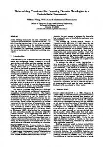
METHODS Calculating Pushrim Forces and Moments The forces and moments acting on the pushrim are illustrated in Figure 1 . Equation 4 provides the information necessary to calculate and analyze critical pushrim forces and moments . The following is a simple mathematical model of the measurements necessary to calculate FX, Fy, Fz, MX, My, and Mz for a six degree of freedom wheel . The measured signals for the six channels are referred to as Vi, and kj are the calibration constants for the six channels. The position of reference beam of the SMARTWheel with respect to top dead center is given by 0, where The distance between the hub and the point at which the pushrim attaches to the beam is given as R . Assuming no crosstalk, the equation for forces and moments, with zero camber for a fixed inertial coordinate system, is :
with forces FX, Fy, and Fz; and the second is the wheel coordinate system with forces F r, Ft, and F L . The forces Fx, Fy, and F z in the world coordinate frame are the components along the absolute x, y, and z axes, respectively, of the resultant F. Similarly, F r, Fr, and F z in the wheel reference frame are components along the wheel spokes, tangential to the pushrim, and along the wheel axle, respectively, of the resultant F . The wheel coordinate frame can be viewed as a rotating version of the world coordinate frame . This information can be exploited to estimate the point of force application . The resultant F is a function of FX, Fy, and Fz or Fr, Ft, and Fz as shown in Equation 5 . F2 =FX+F~,+F=F+Fi+F?
[5]
The resultant force, F, is equivalent to Frot used by Veeger et al . (17) in their studies of wheelchair propulsion kinetics . The tangential force, Ft, is the only component of F that directly contributes to rotation of the wheel . The other components contribute to generating friction between the hand and the pushrim ; however, any force above that required to generate sufficient friction contributes to inefficiency. A metric that can be determined from pushrim force and moment data is the point of force application (PFA). The PFA is fully determined by the coordinates O, R, 0) with 4, the angle referenced with respect to E E E k3cos(O+4~) kicosO k2 cos(O 2 horizontal (see Figure E E V2 kisinO k2sin(O k3sin(O+ 43 ) E 1), R the radius of the k4 k5 k6 V3 E E E pushrim, and zero, the k4RcosO k5Rcos(O+23 ) k6Rcos(8+ 43) V4 E E E position along the z-axis k4 RsinO k5Rsin(O+ 3 2 ) k6Rsin(O+43 ) V5 E E E in a cylindrical coordik3R E E E V6 k 1R nate system with the wheel hub as the origin. FM(t) = K(t)V(t). [4] The only unknown coordinate is e), which can be calculated by using solving for (b in the homogeneous The force and moment vector is represented by FM(t), the rotation matrix between the world and wheel coordinate time-varying coefficients are represented by K(t), and the systems . Camber and drive wheel alignment can also be voltages are represented by V(t) . The E's in K(t) result accommodated by using appropriate homogeneous transfrom the validation by using multiple regression to deterformation matrices about the x and y axes, respectively mine a complete set of coefficients for the voltage-force (25) . Small variations in camber or alignment have minitransformation matrix [K(t)] . Our data show that the conmal effect on results, because their respective homogetribution of the cross-terms stayed below 2 percent for the neous transformation matrices approach identity for small Wheel current SMART . The PFA describes the instantaneous origin for both angles The forces are defined in two coordinate systems: the world and wheel force application coordinate systems the first we have defined as the world coordinate system
165 COOPER et al . Pushrim Forces and Moments
F,
—coscp — Sinop 0
[6]
sirup — COSCp
l
0
0 F
FF+ FF coscp
F2
Because Equation 6 yields two solutions 180° transposed, motion data must be used to determine in which quadrant the hand is located . A convenient property of the homogeneous rotation matrix presented in Equation 6 is that its inverse is given by its transpose . Hence, given the location of the PFA or an estimate thereof, the radial and tangential forces can be determined COSCp
Fr
sirup 0
—since —Cost[ 0
0 0 1
[7]
The tangential force component of Equation 7 is equivalent to the method used by Veeger et al . (17) to calculate the effective force component (Few) from force and hand position, when the camber angle ([3) is zero: costp—F,sincpcosj3+F,sincpsinp .
[8]
Note that we use a different set of coordinate system definitions and angle reference than reported in Veeger's paper. Equation 8 has been written to be consistent with our coordinate definitions . Equations 6 and 7 illustrate the duality between PFA location and estimation of the radial and tangential force components . The PFA in Equation 6 is dependent upon the x,y, and radial and tangential forces . However, these forces are also related by the PFA . We know of no pushrim force/moment measuring system that measures all four sagittal plane forces directly. Hence, the PFA is commonly estimated using kinematic data . It is then applied to calculate the two dependent forces. Calculation of Point of Force Application Previous analyses have assumed that the PFA was coincident with one of the metacarpophalangeal (MP) joints of the hand being studied (12,17,26) . Because of the dual nature of Equations 6 and 7, one of two assump-
sp Point of force application
J
Figure I. Definitions used for pushrim forces and moments.
tions have been made : the PFA is coincident with an MP joint and then the MP joint position is used to estimate F t and Fr in order to estimate the wrist moment (M w); or MW has been assumed to be negligible so that the PFA location could be estimated using Equations 6 and 12 . Since the SMART Wheei is capable of measuring the moments about the x and y axes, M X and My respectively, and the force along the z axis (F t), these values can also be used to estimate the PFA (see Equation 9). My = F,Rcoscp Mr = F,Rsincp
tamp =
[9]
Mr
By using from Equation 9, the assumption about the PFA being coincident with a MP joint and the assumption about negligible M W are no longer necessary . Equation 9 is based upon the assumption that the wrist moments about the x and y axes are small with respect to M X and My, respectively. Calculation of Wrist Moment The SMART Wheei measures the moment about the axle (M O), which consists of two components : the moment applied by the hand (M w), and the torque produced from the product of the tangential force times the pushrim radius . M MW +Fr R
[10]
The moment applied by the hand and the tangential force (Ft) are not measured directly with the SMART Whe OJ .
166 Journal of Rehabilitation Research and Development Vol . 34 No . 2 1997
However, both are required to determine the PFA explicitly using Equation 6.
-Mw
R 2 F2—F2= r z
F +
The small M W assumption, results in an error in F r proportional to M,/R, whereas the error in F r2 is amplified by (2Mz/R2 )MW (neglecting second order effects) . If the wrist moment is assumed to be negligible, then [12] Fr = M' , and F2= F2 R
which can be substituted into Equation 6 to estimate the PFA. A more practical approach is to use the PFA calculated from Equation 9 to calculate the radial and tangential forces using Equation 6 . With these values, the wrist moment can be calculated using Equation 11 . Hence, from purely kinetic data, the PFA, radial force, tangential force, and wrist moment can be estimated, within the validity of the assumptions, with any accurate three dimensional (3-D) pushrim force and moment measurement system. Instrumentation We have previously described 2- and 3-D versions of a force- and torque-sensing SMART wheel (4,5,23,24,27). The SMARTwheel , which mounts to most standard wheelchairs, exhibits several desirable properties, as shown in Table 1, The SMART wheel is fully capable of measuring and recording 3-D pushrim forces and moments during dynamic wheelchair propulsion . Its design is based on equations for a 3-beam (120° apart) system for push-rim force and torque detection utilizing strain gages . During this experiment, two standard polished and annodized aluminum pushrims of 0 .2667 m radius were mounted to the wheels .
Data Collection Data from a single veteran, with paraplegia due to a complete spinal cord injury and who was experienced in manual wheelchair use, were used to examine the methods presented in this technical note. The subject, who had given informed consent to voluntarily participate in this study, weighed 135 kg . The subject propelled a Quickie 1 wheelchair appropriate for his body size, with attached SMART wheel , at 1 .39 m/s at a power output of 14 W on a wheelchair dynamometer for 5 minutes . This is nearly equivalent to rolling over a smooth, hard floor . Data were collected for the last 15 s of the fourth minute . Video data were collected, with a three-camera PEAKS system, at 60 Hz and filtered at 6 Hz ; pushrim force/moment data were collected at 240 Hz and filtered at 30 Hz. Both filters were eighth-order zero-phase Butterworth type . We used a Genloc system to synchronize the cameras, and a computer-generated synchronization pulse to align sampling of video and pushrim force/moment data . For the purpose of this study, the propulsion phase was defined as the period when the moment about the hub, Mz, deviated more than 5 percent from baseline, until it once again returned to baseline and remained within 5 percent . The kinematic data were selected coincident with the propulsion phase defined by the kinetic data . This eliminated the need to estimate from kinematic data whether the hand was in contact with the pushrim. Data Analysis The data from five consecutive strokes were analyzed . Motion and force data in three dimensions were Table 1. Properties of the latest version of the 3-D SMART wheel . Property
Forces
Moments
Wheel Angle Natural Frequency in Degrees
Percent Linearity
98 .9%
99 .1%
N/A
N/A
Range
at 155 N
± 77 N®m
0 — 360
N/A
Precision
0.6 N
0 .6 Nim
0 .18
N/A
Resolution
1N
1 Nom
0 .2
N/A
Independent Nonlinearity
5%
0 .9%
N/A
N/A
Sagittal Plane Transverse Plane
N/A
N/A
N/A
150 Hz
N/A
N/A
N/A
100 Hz
167 COOPER et al . Pushrim Forces and Moments
collected in synchrony. Each variable was calculated using the required input data at each sample instant . This resulted in five sets of time series data for each variable (e.g ., tangential force, PFA) . A point-wise mean and standard deviation (SD) was calculated for each stroke (i .e., the mean and SD were calculated from the five values for all variables corresponding to each stroke at each sample instant) . This resulted in a time series curve representing the point-wise mean and point-wise SD for each variable. Minimum and maximum values were determined from the point-wise mean and SD time series data.
est in the mid-propulsion phase (4 .2 N for Ft and 1 .5 N for M7 °R -'). There is also an increase in the variability (SD) around the impact spike, defined as an initial rapid rise in force, for Ft (SD=39 .1 N) from Equation 7 . A large portion of this variability may be due to time shifts for the impact spike between strokes. The wrist moment can be estimated by assuming that the PFA is coincident with an MP joint or the calculated PFA, with Equation 9, based upon the 3-D moments can be used . The mean and SD curves for three strokes 60
RESULTS
40
The 3-D forces and moments for the third stroke of the five stroke data set are presented in Figure 2. The gray regions represent those areas where the variability of several common wheelchair propulsion biomechanics metrics are highest. The difference between using the calculated PFA from Equation 9 and estimated PFA coincident with the second MP joint, as determined from kinematic data, is illustrated in Figure 3. The PFA tends to lead the second MP by 0 .2 radians (11 .5° or 5 cm) on average for this subject . Figure 2 also shows that the PFA varies within the hand throughout much of the propulsion phase of the stroke . This is demonstrated by the variable distance between the second MP and the PFA . The sensitivity of the PEA, from Equation 9, to small moments manifests itself as large SDs near the beginning and ending of each stroke . The SDs for the second MP are smaller in these regions . The maximum SD for the second MP is 0 .23 radians compared to 1 .40 radians for the PFA . However, the SDs are small for both the PFA from Equation 9 (minimum SD is 0.04 radians) and second MP (minimum SD is 0.01 radians) during the mid-sections of the propulsion phase when the moments (M x, M y) are largest. The mean and SDs for three strokes of the tangential forces from Equation 7 determined using the PFA calculated from Equation 9, and the tangential forces calculated with Equation 12 using M z assuming Mw is negligible are presented in Figure 4. This subject's data show the tangential force (Ft) from Equation 4 to be larger than would have been estimated assuming no wrist moment contribution (M zR— ') in Equation 12 . The mean of the difference between the tangential force (Ft) and (M z ®R_ 1) is 35 .4 N. The SDs for both methods (i .e., using Equations 7 and 9, or using only Equation 12) are small-
20 0 O
3 -20 z -40 -60 -80 -100
-120
0 .08
0 .17
0 .25 0.33 Time (seconds)
0 .42
0 .50
0 .08
0 .17
0 .25 0 .33 Time (seconds)
0.42
0.50
Figure 2, Three-dimensional pushrim forces and moments.
168 Journal of Rehabilitation Research and Development Vol . 34 No . 2 1997
DISCUSSION
0 .1
0 .2
0 .3
0 .4
0 .5
time (seconds)
Figure 3. The difference between calculating the point of force application (PFA) using Equation 9 versus assuming the PFA is coincident with the second metacarpophalangeal (2nd MP) joint . The PFA is dependent upon the ratio of two moments and may become unstable near the end of the propulsion phase when these moments are small.
Analysis of wheelchair pushrim forces and moments lacks a standardized foundation for analysis . This technical note provides an attempt to clarify some of the techniques presented in the literature, and to provide some insight into means of removing some of the assumptions currently used . Several investigators have modeled wheelchair propulsion to study mechanical efficiency (6,14,15,20), and to study and model propulsion dynamics (7,8,10,17) . Wheelchair ambulation is an important form of locomotion that has only recently received substantial attention . Studies to date have assumed that the PFA is coincident with a marker on one of the MP joints (9,12,17,26) . This has been required to obtain an estimate of the applied wrist moment, which has been proposed as a contributor to the high incidence of carpal tunnel syndrome by several investigators (17,26). By using pushrim 3-D force and moment-sensing devices, the PFA can be calculated using Equation 9. Asato et al . (4) showed that there is about an 11° difference in estimating hand contact position using kinematic data versus kinetic data . This was likely due to the hand obscuring the sagittal plane view of the pushrim during contact and release . Therefore, it is important to use kinetic data to determine hand contact. Our results indicate that the PFA from Equation 9 leads the second MP by about 11 .5° on average . This result is more likely due to the fact that the PFA location can vary within the hand
Figure 4. Mean and standard deviation (SD) for three strokes of the tangential (Ft) force calculated using the PFA from Equation 9 and Fx , Fy , and the homogeneous transformation matrix in Equation 7 . Also, the mean and SD for three strokes for an estimate of the tangential force (M,'R21), which assumes no wrist moment contribution.
for these two methods are illustrated in Figure 5. The mean difference between the wrist moment for the two methods is 0 .6 N•m. The variation from stroke-to-stroke is similar for both methods as well, maximum SDs are 6 .6 N•m for M W (PFA) and 6.4 N•m for MW (second MP) and the minimum SDs are 0 .3 N•m for M W(PFA) and 0 .1 N•m for M w (second MP) .
time (seconds)
Figure 5. Time series plot of the mean and standard deviations for three strokes of the wrist moment estimated with two methods : 1) Uses the PFA calculated from applied moments M x and My to calculate the wrist moment [M 0 (PFA)] ; 2) Assumes that the second MP joint is coincident with the PFA to estimate the wrist moment [M 0 (2nd MP)].
169 COOPER et al . Pushrim Forces and Moments
and, because the hand can apply a moment, venture outside the hand . The PFA is restrained to the pushrim by definition . Hence, the variations in the data presented in this technical note are fundamentally different from those of Asato et al . and are based upon different metrics. Depending on the variable being calculated and the period of the stroke being studied, the second PFA may be preferable to the second MP. At the extremes of the propulsion phase, the second MP appears to be more stable from stroke to stroke . The method presented in Equation 9 to calculate the PFA results in very large SDs near contact and release of the pushrim . Our results show that the estimate can provide results that are not possible with standard wheelchairs (e .g., -1 .5 radians) . This would suggest caution when applying Equation 9 within the gray region indicated on Figure 2 (i.e., within the first and last 5 percent of the propulsion phase) . However, Equation 9 may provide some important information as to how the PFA varies within the hand during the midsection of the propulsion phase when it is a stable metric. The location of the PFA can be used with the Equations 7 and 9—11 presented in this note to estimate the wrist moment. Some studies have assumed that the wrist moment was negligible when calculating the radial and tangential pushrim forces (11,12,26) . Our data indicate that wrist moments are non-zero, which can result in error due to this assumption . The PFA also influences radial and tangential forces, which are important components of the resultant force vector because they present data on stroke efficiency in a clear and concise manner . Tangential force is the only component of the resultant force that contributes directly to rotation of the wheel . Radial and axial forces, above those required to generate friction, only contribute to inefficient expenditure of energy and unnecessary loading of muscle and joint structures. The wrist moment about the z-axis applied by the hand to the pushrim, M W, is not measured directly . We have shown that it can be calculated from the difference between the torque around the wheel axle produced by the tangential force, Ft, and the moment that is measured around the axle, Mz. The wrist moment can also be estimated by assuming that the PFA is coincident with an MP joint or the calculated PFA based on Equation 9 using the 3-D moments . The two methods yield similar results for this subject, with some deviation being observable in the last 40 percent of the propulsion phase . The wrist moment is estimated to be negative (counter-clockwise), in opposition to the hub moment, for both models during
most of the stroke . This type of behavior might correlate with wrist injuries such as carpal tunnel syndrome. In conclusion, we have presented methods for analyzing wheelchair propulsion pushrim forces . The methods presented in this note provide a framework for interpreting wheelchair propulsion forces and moments . By applying these methods, fewer assumptions are required to calculate tangential force, radial force, point of force application, and hand moments . Although the data are for a single subject, our results indicate that alternative methods for calculating or estimating point of pushrim force application, tangential force, and wrist moments may yield noticeably different results . The most appropriate method for analyzing wheelchair propulsion biomechanical data remains specific to the experimental question and limitations . However, this note should provide readers with some insight into the possible sources of variability between studies that may not necessarily be due to differences in subjects or propulsion techniques . In order to make cross-validation of wheelchair biomechanical studies feasible, some standardized means for presenting and defining key variables must be agreed upon . This could lead to sample sizes and reliable metrics that are sufficient to provide important clinical data regarding the high incidence of upper limb pain and injury among manual wheelchair users.
ACKNOWLEDGMENTS The authors wish to thank the subject for volunteering his time for this project, and Paula Stankovic, Carmen DiGiovine, and Jess Gonzalez for their assistance. REFERENCES
2. 3.
4.
5.
Bobbert MF, Schamhardt HC . Accuracy of determining the point of force application with piezoelectric force plates. J Biomech 1990 :23(7) :705—10. Morris JRW. Accelerometry—a technique for measurement of human body movement . J Biomech 1973 :6 :729—36. Amirouche FML, Ider SK, Trimble J . Analytical method for the analysis and simulation of human locomotion . J Biomech Eng 1990:112 :379—86. Asato KT, Cooper RA, Robertson RN, Ster JF . SMART Whe C1 : development and testing of a system for measuring manual wheelchair propulsion dynamics . IEEE Trans Biomed Eng 1993 :40(12) :1320—4. VanSickle DP, Cooper RA, Robertson RN . SMART"'heeI : development of a digital force and moment sensing pushrim, In :
170 Journal of Rehabilitation Research and Development Vol . 34 No . 2 1997
Differences in performance between trained and untrained subProceedings of the 18th International RESNA Conference, Vancouver, BC, Canada. Washington, DC : RESNA Press jects during a 30-s sprint test in a wheelchair ergometer. Eur J 1995 :352-4. Appl Physiol 1992 :64 :158-64. 6 . Cooper RA . An exploratory study of racing wheelchair propul20. Veeger HEJ, van der Woude LHV, Rozendal RH . A computersion dynamics . Adapt Phys Act Q 1990 :7(1) :74-85. ized wheelchair ergometer. Scand J Rehabil Med 1992: 7. Cooper RA . A force/energy optimization model for wheelchair 24 :17-23. athletics . IEEE Trans Syst Man Cybern 1990:20(2) :444-9. Strauss MG, Moeinzadeh MH, Schneller M, Trimble J . The . A systems approach to the modeling of racing 8. Cooper RA development of an instrumented wheel to determine the hanwheelchair propulsion (a technical note) . J Rehabil Res Dev 1990 :27(2) :151-62. drim forces during wheelchair propulsion . In : Proceedings of 9. Gehlsen G, Bahamonde R . Shoulder joint forces and torques in the American Society of Mechanical Engineers (ASME) Winter wheelchair propulsion . In : Proceedings of the North American Annual Meeting, 1989 :53-4. Congress on Biomechanics (NACOB) II, Chicago, IL, 1992 : 22 . Strauss MG, Maloney J, Ngo F, Phillips M . Measurement of the 459-60. dynamic forces during manual wheelchair propulsion . In: 10. Su FC, Lin LT, Wu HW, Chou YL, Westreich A, An KA . ThreeProceedings of the 15th Annual Meeting of the American dimensional dynamic analysis of wheelchair propulsion. Society of Biomechanics, 1991 :210-1. :13(4)326-42. Chinese J Med Biol Eng 1993 11. Rodgers MM, Tummarakota S, Lieh J, Schrag DR . Three- 23. Cooper RA, VanSickle DP, Robertson RN, Boninger ML, dimensional dynamic analysis of joint reaction forces and Ensminger GJ . A method for analyzing center of pressure durmoments during wheelchair propulsion . In : Proceedings of the ing manual wheelchair propulsion . IEEE Trans Rehabil Eng North American Congress on Biomechanics (NACOB) II, 1995 :3(4) :289-98. Chicago, IL, 1992 :457-8. 24. Cooper RA, Asato KT, Robertson RN, Ster JF . 2-dimensional 12 Rodgers MM, Gayle GW, Figoni SF, Kobayashi M . Lieh J, kinetic analysis of manual wheelchair propulsion with an Glaser RM . Biomechanics of wheelchair propulsion during improved SMARTwheei . In : Proceedings of the 14th Interfatigue . Arch Phys Med Rehabil 1994 :75 :85-93. . Computer controlled national Conference of the IEEE Engineering in Medicine and 13 . Niesing R, Eijskoot F, Kranse R, et al wheelchair ergometer. Med Biol Eng Comp 1990 :28 :329-38. Biology Society, Paris, France, 1992 :14(4) :1544-5. 14 . van der Woude LHV, Veeger HEJ, Rozendal RH . Propulsion 25. Cooper RA, Rehabilitation Engineering Applied to Mobility technique in hand rim wheelchair ambulation . J Med Eng Tech and Manipulation . London, UK : Institute of Physics 1989 :13(1&2)136-41. Publishing, 1995. 15. van der Woude LHV, Janssen TWJ, Meijs PJM, Veeger HEJ, Robertson RN, Cooper RA . Kinetic characteristics of wheel26 . Rozendal RH. Physical stress and strain in active wheelchair chair propulsion utilizing the SMART wheei In : Proceedings of propulsion : overview of a research programme . J Rehabil Sci the 17th Annual Meeting of the American Society of Bio1994 :7(1) :18-25. 16. Veeger HEJ, van der Woude LHV, Rozendal RH . Wheelchair mechanics, Iowa City, IA, 1993 :202-3. propulsion technique at different speeds . Scand J Rehabil Med 27. Watanabe KT, Cooper RA, Ster JE A device for studying 1989 :21 :197-203. wheelchair propulsion dynamics . In : Proceedings of the 13th 17. Veeger HEJ, van der Woude LHV, Rozendal RH . Load on the International Conference of the IEEE Engineering in Medicine upper extremity in manual wheelchair propulsion . J and Biology Society, Orlando, FL, 1991 :1817-8. Electromyogr Kinesiol 1991 :1(4) :270-80. 18. Veeger HEJ, van der Woude LHV, Rozendal RH . Within-cycle characteristics of the wheelchair push in sprinting on a wheelchair ergometer. Med Sci Sports Exerc 1991 :23(2) :264-71 . Submitted for publication January 17, 1996. Accepted in revised form May 8, 1996. 19. Veeger HEJ, Lute EMC, Roeleveld K, van der Woude LHV.