What is needed is a method to create a transfer of intent of the designer or an option list for the RP system accompanying the transfer of geometric data towards ...
METHODS FOR OPTIMAL USAGE OF LARGE SIZED PHYSICAL MODELS DURING CONCEPTUAL DESIGN Johan J. Broek Imre Horváth Alex F. Lennings Bram de Smit Faculty of Design Engineering and Production Sub-faculty of Industrial Design Engineering Delft University of Technology
ABSTRACT Large sized free form objects of different materials are widely used in various applications. Currently Rapid Prototyping, based on layered techniques are not suited for manufacturing such kind of objects, because of the large number of layers and limitations of the size. This paper reports a new method that is very appropriate for such objects. A method of thick layered object manufacturing is presented, that is based on a higher order approximation of a nominal shape and a flexible cutting tool. The method allows the production of physical prototypes that need less or no finishing. The process is arranged in a sequential way and will be a highly automated. A hierarchical decomposition of the CAD geometry into components, segments, layers and sectors, based on a morphological analysis is proposed. In order to meet the designer’s intent, some very feasible provisions have been introduced, like the application of inserts, the editing of the shape, hollow objects, etc. The method facilitates manufacturing and part reassembly for physical prototypes with requested functionality. Due to different possibilities in decomposition and producing of a physical model much attention must be paid to the efficiency of the process.
KEYWORDS Rapid Prototyping, Physical Models, Conceptual Design, Layered Manufacturing, Geometric Decomposition, FF-TLOM, Flexible Blade Cutting,
1. INTRODUCTION In the process of product design, physical models are used for testing and reasoning and are
commonly accepted among designers and stylists [Geuer, 1996]. These models that are made of different materials, often don’t need to be of the same material and detailed like the final product. Often applied materials are plastic foam, paper, cardboard, plywood, clay, plaster, compound materials, etc. The application of these models might be manifold. In the concept phase of the design process the physical model supports reasoning, communicating with customers, testing for functionality and/or requirements of the product. The use of physical models during the conceptual phase of a design process might lead to a better quality of the final product. In the conceptual design phase, a physical model is often used and prepared for a short period of time. In such cases a minimal amount of effort must be put into the realization of such a model without disturbing the requested functionality for a preferred application. For testing of only one single or a few aspects of functionality of a product, the physical model might be tailored for that specific test procedure. According to [Lennings, 2000] the application of Rapid Prototyping and during Conceptual Product Design is referred to as concept modeling. However, when Rapid Prototyping is used throughout all stages of a design process, it’s called physical concept modeling. The success of concept modeling depends on: integration of Rapid Prototyping into the conceptualization process, ability to fabricate physical models in a fast way, adaptation of the models to the evaluation and presentation purposes, the transfer of geometric representation into the preparation stage of the Rapid Prototyping
process. Depending on the application requirements the following physical models are to be considered: shape models (partial or complete), presentation models (detailed, textured and finished), partly or fully functional models, models including alien parts (inserts, frames), tooling models (null series) and models for kinematics testing. Each type of model needs a specific exterior, treatment and fabrication method of the physical model due to the difference in requirements. The application of such kind of physical models in the design process requires Rapid Prototyping processes that must support different Rapid Prototyping options to adapt optimally to the required final result. Another method of design evaluation and reasoning is completely based on computer evaluation and is called virtual prototyping. This paper, however, will not deal with virtual prototyping. Both physical models and virtual prototyping are accepted as a supportive mean of conceptual design, having an overlap of functionality but each of them having specific characteristics too.
1.1. Physical models in Conceptual Design According to the needs and intentions of the designer, physical models must support his endeavor after an efficient design process. The designer wants to obtain as early as possible correct and supportive information during the design process. And emphasizes the need of physical models, virtual models, etc, in an early stage of a design process. These models are used for only one or a few specific aspects of reasoning, verification or (functionality) testing. It is obvious, that it will have an impact on extent and structure of the physical model. The intention of the designer during conceptual design is to test one single or a restricted group of functionality items and than it is most likely that preparing and manufacturing of a complete physical model is too expensive. It takes too much time and effort to realize such kind of a model. According to the expectations the model will be used for a very short period. As a result of testing, the design might be changed and the produced model is no longer valid and subsequently wasted. Furthermore
Design Process CAD system
Geometry Transfer
Consistency Check
Rapid Prototyping Preparation Process
Designer
Designer Intend
Functionality Requirements Rapid Prototyping Options
Fabrication Stacking & Assembly Physical Model
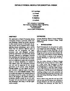
Figure 1. Interface between design process and RP process it is most likely that a detailed model might still provide not anymore information than a simplified version will do for specific aspects. What is needed is a method to create a transfer of intent of the designer or an option list for the RP system accompanying the transfer of geometric data towards the preparation part of the Rapid Prototyping system (figure 1). However, at this moment none of the formats supports such kind of functionality transfer.
1.2. Conventional RP processes Today materialized models are often generated from computer-generated data and produced by a specific Rapid Prototyping process. A distinction can be made in two fundamental approaches, namely decremental and incremental processes. In a decremental process a solid block of material (stock). Is sequentially cut, machined, sculptured or shaped to the nominal shape (geometric CAD data). Typical examples of decremental methods are the Sculpting Robot [Tangelder, 1998] and high speed milling [Gunnink, 1998]. An important issue is the detection and the avoidance of tool interference with the stock, which might be very calculation intensive and not always ascertain success.
Manufacturing processes based on the incremental method are highly or completely automated. The principle is the subdivision of CAD data in easy to manufacture parts (like very thin slices). Therefore, a dominant part of Rapid Prototyping processes is based on so-called Layered Manufacturing Technologies (LMT). The shape is built by deposition of layers, each layer is manufactured separately and finally the layers are stacked onto each other to create a physical model. Different incremental technologies exist on the RP-market, e.g., 3D printing, stereolithography, layered object manufacturing (LOM), selective laser sintering and fused filament deposition. In general, the available conventional (incremental) LMT technologies are the best for the manufacturing of small and midsize objects. In these processes the applicable layer thickness is relatively small compared to the dimensions of the model [Kochan, 1993]. More information about these layer-oriented technologies are presented in [Suh, 1994], [Marsan, 1997], [Wall, 1992], [Kumar, 1998b].
1.3. Large sized physical models Large-sized, free form physical models (up to 6m and beyond) are applied in the household equipment, automotive, advertisement, and entertainment industry. And are applied for scenery pieces in movie film making, for stage settings in theatres, sculptures, ornaments and for large-sized human or animal mannequins. In scientific research and industry, these models support the visualization of mathematical models, the testing of human-product interaction, analyzing aerodynamic and hydrodynamic behavior, as well as aesthetic and ergonomic impressions. Physical models of that size need a large amount of material for model realization and accordingly these are made of soft and lightweight materials. Neither decremental nor incremental processes are well suited for large-sized applications. The decremental process needs a large amount of machining time with very expensive equipment (working space is proportional to the stock volume). Common LMT technologies need such a large amount of layers that the fabrication time becomes excessive, because of the extended area of a deposited thin layer and the related, attainable accuracy [Gibson, 1997]. Normally the dimensions of the manufacturing equipment limit the object dimensions. Therefore these large sized models
need a different treatment. A useful method is based on a combination of thick layers and a decomposition of the nominal shape (a CAD geometric model) into smaller manageable parts. In recent years thick layer object manufacturing (TLOM) has been demonstrated in [Thomas, 1996], [Hope, 1998] and [de Jager, 1998]. In these examples the front faces of the thick layers are approximated by a first order surfaces (ruled surface or slanted front faces)of the nominal shape. And the layer thickness is adapted to the accuracy needs (adaptive slicing). Systems such as Trusurf, Formus and Shapemaker offer specific technologies to fabricate large-sized objects in such a manner. The fabrication of large-sized free-form physical models by layered manufacturing is a true challenge of our research. In order to extend conventional LOM to the large size domain the focus of the research is put on a method of freeform thick-layered object manufacturing (FFTLOM) [Broek, 1998]. This technology combines the advantages of the decremental and incremental methods, and is considered as an extension of the existing Rapid Prototyping applications.
2. FREE FORM THICK LAYERED OBJECT MANUFACTURING The principle of the proposed FF-TLOM technology is the free form shaping of the front faces of each layer. Afterwards, the machined layers are assembled or stacked to become a physical model. The free form shaping implies a shaping technology based on a concept of a curved cutting tool and a higher order approximation method of the nominal shape. This enables applications of much thicker layers with the same or better accuracy of the model and smoother outside surfaces (a better layer-thickness/accuracy ratio). The application of the FF-TLOM technology needs less or no shape finishing effort for an adequate functional usage of the model. However, a higher order approximation and free form shaping require very sophisticated manufacturing techniques. E.g. methods such as smearing of hardening plaster or cutting light and soft materials such as foam might be used for the actual shaping. The proposed technology uses thick high-density polystyrene foam layers, which front faces are shaped according to the principle of free form cutting. This light weight material (ranging from 28 to 40 kg/m3) is cheap, readily available in standard formats and different layer thicknesses
and is commonly accepted for physical models. The cutting tool is a flexible hot electrically heated knife. The curvature of the blade is continuously adjusted according to the local nominal shape of the geometric model). The free form layer shaping is a new developed technology and will be described in more detail in the next paragraph.
2.1. Flexible blade cutting Currently, in the domain of thick layered object manufacturing (TLOM) well-known straight cutting techniques are applied with a less sophisticated approximation of the local, nominal shape. In this case a slanted front face or a ruled surfaces represents the layer front faces. The related shaping technologies are e.g. water jet cutting, side face milling, hot wire and hot knife cutting. In case of adaptive slicing, the thickness of each layer depends on the maximum allowed shape error and the available standard slab thicknesses. Therefore the applied layer thickness will vary with each change in local curvature along the nominal shape. Like most conventional layered manufacturing technologies, a typical TLOM process preparation starts with finding an optimal orientation that will require a minimal number of slices. The slicing of an object is performed in one single orientation for the complete object. Special attention must be paid to local changes in the nominal shape and to degenerated layers (e.g. first and last layer of an object). A valuable extension of the TLOM method is an adaptation to the local curvature requirements in such a way that a larger layer thickness can be applied. Our group is developing a flexible blade cutter for cutting polystyrene foam. The cutting blade is supported at both ends in a U-shaped support structure. Both supports can be rotated introducing an inclination at both blade ends. Shape and curvature of the blade are defined by the blade inclination, the length of the blade, the position of the supports and the assumption that the blade is shaped according to minimal strain energy (figure 2).
Figure 2. Principle of the FF-TLOM cutting head electrical properties of the cutting blade. The cutting tool is applied tangential to the slicing contour of the layer front face. The plane, in which the blade bending is performed, is kept perpendicular to the front surface of the layer. Preliminary cutting tests indicate that the technology is feasible [de Smit, 1999]. First concepts and implications of the FF-TLOM cutting equipment are elaborated. [Sudijono, 1999] provides in a global manner the system requirements. [Ferro Pozzo, 2000] investigated the kinematics of tool- and related foam slab. [Gil Docampo, 2000] explored the foam slab stability and fixing. As explained before the blade is heated electrically and must be bent during heating in a flexible way. The cutting blade has to be flexible enough to take up the requested tool profile, referred to as tool shape. The tool curve must approximate a shape curve of the CAD model (nominal shape) and must also be rigid enough to sustain the tool shape during cutting. These conditions of flexibility at high temperature introduce specific material requirements. At the same time the blade material must
The cutting action is performed by heat radiation of the electrically heated blade, which locally melts the foam and creating a gap in which the cutting blade can proceed continuously. In figure 3, an example of free form layer cutting is presented. The amount of electrical power depends amongst other things on the selected cutting speed and the
Figure 3. FF-TLOM process simulation
have electrical resistance in for the blade heating and must also have good dynamic heating characteristics. The blade material is very important and it seems to be most likely, that the requested material properties can’t be united in one specific type of material [Wibowo, 1999]. The application of a compound material for the blade will be considered. The cutting blade must be bent and match to the local nominal shape curve for manufacturing reasons and control of the blade. From a mechanical standpoint of view the blade is a very slender bar (small cross section / length ratio) [Frish-Fay, 1962] and behaves like a "physical spline". And will take up its shape according to the principle of "minimum strain energy". A mathematical model for the blade mechanical behaviour is required. The first attempt was to develop a function of the shape of the blade based on the mechanical properties and degrees of freedom mentioned before. The higher order mechanical model, however, consists of a non-linear differential equation, for which, until this moment, no exact analytical solutions are provided [Horváth, 1998]. Next a geometric modeling of the blade curve is introduced to solve the approximation calculations and the matching of the blade shape with the nominal object shape. The assumption is that irrespective of the blade cross section the curved blade can be substituted by its two-dimensional profile curve of "least strain energy" (lse) and prescribed length [Horváth, 1999a]. However, the direct calculation of each curve takes too much computing time. The implemented solution is a set of parametric “lse” curves computed beforehand and offline, indexed and put into a database. Since the tool profile has to be adjusted continuously the shapes are calculated at sufficient small increments. Practical measurements are needed to calibrate the bending characteristics of the cutting blade [de Smit, 2000]. It will be a challenge to develop a reliable cutting tool, and an application methodology for the FF-TLOM system.
2.2. Geometric Decomposition The sequence of Rapid Prototyping preparation starts with transfer and input of geometric data (a CAD model - nominal shape) into the analyzing and decomposition section FF-TLOM system. The data is transferred in a standard geometric transfer format. Different standard formats are available.
An overview is presented in [Kumar, 1997]. A very commonly applied transfer standard is the STLformat, which contains no morphological information. All solid modelers deliver correct STL transfer data. However, surface modelers fundamentally have some difficulty to produce correct STL files. On the market special software is available which can restore the consistency of the STL data. NURBS representations are very elegant in terms of amount of transferred data and exact representation. Practically, the STEP transfer format combined with the geometric representation of NURBS is applied for the input of the geometric data into the FF-TLOM system [Rock, 1995]. The transfer of specific nominal shape features into the FFTLOM system might facilitate the shape analysis and geometric decomposition of the model. In common LMT the notion “decomposition” is used for the slicing of the nominal shape into an advantageous orientation. The slicing criteria are related to manufacturability, minimum number of deposited layers, accuracy and finishing effort. The morphological complexity and geometric articulation of the geometry has significantly less impact on the fabrication process with thin layers than with thick layers, while these geometric characteristics must be represented in the front face of the layers. In case of large-sized free form physical models, the application of very thick layers will reduce the manufacturing time remarkably. At the same time, if the mentioned characteristics exist, physical model fabrication yields a complex manufacturability problem, even when FF-TLOM techHierarchical elements Manufacturing
Decomposition assembly functional
assembling component composing
morphological segment
stacking
geometric layer technological
fitting sector
Figure 4. Decomposition and assembly process
nology is applied. A reasonable way of reducing the manufacturing and handling problems is the introduction of artifact decomposition. The FF-TLOM preparation phase is based on the analysis of the nominal in order to decompose the geometry into elements, which are efficiently manufactured, assembled, stacked and finished. Furthermore, the decomposition will depend on the required functionality of the model and/or the type of physical model realization. In figure 4 the decomposition for FF-TLOM technology (right side of figure) is ordered in four hierarchical levels. Also, in figure 4 at the left side four hierarchical manufacturing or recombining levels of the physical prototype is presented. Generally, the decomposition must support an efficient and competitive Rapid Prototyping fabrication process and must produce a functional prototype. Geometric models exist commonly of complete assemblies, which are generated and adapted during product development process and physically prototyped. The notion assembly is related to a system of parts, units or components that is in a specific relational, functional and morphological connection to each other. For the purpose of Rapid Prototyping assemblies are decomposed for reasons of structure, shape, size, materialization, fabrication, handling and/or functioning. A functional decomposition of assemblies is defined by the following actions: the assembly is subdivided in single parts, each part has a known relationship to the complete assembly related to the required functionality (kinematics: degrees of freedom or rigid connections to the other parts). Next the complete collection of assembly parts is analyzed for required functionality and inserts. An insert is defined as an alien part, which is not manufactured by the FF-TLOM technology. Some examples of inserts are described in section 3.1. Those inserts are considered as alien parts, but are included into the logistic support of the system, while it will influence the assembly sequence of the physical model. For functional testing of one single or a few functional issues and focusing on these characteristics which are needed for this restricted functionality test, this might result for efficiency reasons in an analysis of the minimal functionality of the required physical model. Until that moment, only the designer is aware of the extent of the tests and only
he is able to decide on details of the tests and the materialization of the required physical model. Rigidly interconnected parts are considered to be one rigid subassembly and will be manufactured likewise. Another decision can be made about the required kinematic freedom of the parts for testing purpose only. Decisions about the required kinematics and degrees of freedom of the assembly parts can not be automated because the functional decomposition depends on the designer’s personal intent and his knowledge about the functioning of the prototype during testing. In general, a minimization of the number of parts will have a positive influence on the efficiency of the process. In that way, it is advisable to consider rigid connected parts or subassemblies to be one single part and to manufacture it accordingly, unless the required functionality of the final model is obstructed. Parts, units, subassemblies that are manufactured in one single piece without reduction of requested functionality are referred to as components. When the components are decided on, the generation of an enclosing boundary of the component can be performed in an automatically way. These components are elaborated and decomposed at the next hierarchical level. A decomposition of the components into segments is based on partly morphological and partly technological issues. Based on morphological considerations, components can be subdivided into pieces. The process is called segmentation, and the parts are called segments. As a result of segmentation, the dimensional and morphological complexities are reduced and it will provide better conditions for manufacturing. The morphological issues are related to detect shape characteristics, which need special care in the FF-TLOM technology. Attention must be paid to the discontinuities in curvature and tangency, the so-called singularities [Horváth, 1998], regions of high and moderate change of curvature and flat regions. The technological issues are related to the choice of an optimal segment orientation for slicing and stacking, the applied layer manufacturing technology and the manufacturing efficiency in time and in costs. The task is to decompose the component into segments, taking into account special shape characteristics in such a manner that it supports optimally the efficient production of a physical model according to the requirements. An algorithm might automate the decomposition of components
into segments. In [Horváth, 1999b] a segmentation method based on the FF-TLOM technology is developed. The assumptions are: (a) the nominal shape is a morphological well behaved object, (b) the need for an extreme long blade and extreme arm positions are avoided; the pitch of the tool is kept in between +45? and -45? , and is referred to as pitch constraint, (c) support structures for assembly activity are considered to be external devices, and (d) different efficient segmentation solutions are possible depending on the requirements.
Figure 6. Matched tool curves along a layer contour
The component segmentation starts with the selection of a segmenting orientation, and will depend on efficiency factors like fabrication time and cost, complexity of the task, the minimal cutting length for the manufacturing of the complete physical model, etc. When the orientation is selected the calculation and shape interrogation can start. When
the nominal shape. This curve is matched against a tool shape curve under tolerance constraint and at a specific location. In order to speed up the matching process and to minimize the computing effort, a library of pre-calculated tool profile curves is available. All curves in the library are “least strain energy” curves. All the available tool shape curves in the library are applied for matching and the relevant tool data is stored for all successful matches. However, when a match fails another tool shape curve from the library or another section of the same tool curve is considered. When no match is found against the curves of the tool shape library, then the section length of the tool shape curve is decreased and correspondingly the thickness of the applied layer will be reduced, until matching is achieved. This procedure is repeated multifold along the slicing contour at the circumferential matching positions, defined by the geometric properties of slicing contour. The result is a set of successfully matched tool shape curves at each se-
Figure 5. Feature points and segmentation regions
A
Flexible cutter control
B 150
Angle top in degrees
C
Angle bottom in degrees Blade length in mm Section length in mm
100
Parameters
the surface normal is collinear with the segmentation orientation then typical segmentation features (feature points) are detected (figure 5). In [Horváth, 1999b] different feature point situations are classified. Near those feature points the positions of maximum pitch of the cutting tool are calculated. Those regions are analyzed more profoundly for feasible segmenting (figure 5). This method of shape analysis for segmenting purposes is very effective and not computing intensive. A geometric decomposition of the segments into thick layers is called slicing. The slicing process can be automated on the basis of a slicing algorithm. The method of slicing is based on a higher order approximation and on the application of adaptive layers [Horváth, 1999a]. The local nominal shape curve is defined by the intersection curve of a plane perpendicular to the slicing contour and
Section position in %
50
0 0
10
20
30
40
50
60
70
80
90
-50 Region A
Region B
Region C
-100
Distance along contour in %
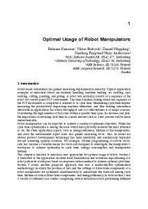
Figure 7. Typical flexible blade control parameters for sector cutting
100
Figure 8. Example of a decomposed object lected position at the slicing contour of the layer (see figure 6). Individual tool curves along the contour are applied for correct tool shape control during the movement along the tool path. An example of the cutting of a FF-TLOM part is presented in figure 7. The minimal applicable section height of the blade is selected and related to that an allowable layer thickness is calculated. Next, a standard layer thickness, which is the maximum standard slab thickness fitting inside the calculated layer thickness, is selected from the foam stock. The tool shape data at the periphery is analyzed and a family of tool shape curves and tool control data is selected, which supports minimal tool adaptation and movements during the cutting of the specific contour. For reasons of minimal finishing effort and optimal appearance, a prototype must at least have a first order continuity in the transient regions of the subsequent layers. This principle requires the same contours at the contact planes of the layers. In order to satisfy these requirements, error compensations in the pitch of the cutting tool and a tolerance check are performed. The tool data is now prepared for tool path calculations. The top of the elaborated layer becomes subsequently the basis of the slicing calculations of the next layer. The choice of slicing positions will be influenced by the achievable pre-
ciseness of the shape approximation. An extended description of this issue is presented in [Horváth, 1999a]. An example of an object decomposed from a component into segments and layers is presented in figure 8. In [de Jager, 1998] specific TLOM problems are described due to the fact that only one single slicing orientation for the complete physical model is applied. These problems are the branching problem, the correspondence problem and the degenerated layers. The branching problem occurs when during slicing the number of closed contours (loops) changes in successive slicing levels. When the next slicing positions contain more closed slicing contours then locally the shape is branched in two or more branches. The other way around branches might joint. In both cases the geometric information of the shape in between both cross-section levels is not suited for TLOM and will need local segmenting of the nominal shape. In some cases a branching problem is avoided when the slicing orientation is changed. The correspondence problem occurs, depending on the geometric representation, when adjacent slicing levels contain multiple contours and when the interconnection of the individual slicing contours is subject to multiple interpretations. During slicing some regions of individual layers become very thin and combined with an extreme front face inclination it might occur that the manufacturing of such a layer is impossible with the normal TLOM techniques. Those layers are referred to as degenerated layers. Applying a geometrical decomposition and a local change of the slicing orientation might solve the problem. Technological decomposition of layers into sectors is a technological issue. Tool interference with the foam slab, hollow layers, maximum working space of the flexible cutting machine, transportation, handling of layers (e.g. weight, dimensions), stacking provisions, rigidity of the slab and model, and stacking of the sectors are all considered in this geometric decomposition. Each of the enumerated issues will introduce a specific decomposition of a layer into sectors. Some issues are strongly related to precise sectoring such as local extreme curvature, undercutting, and tool holder interference with the foam slab. While other issues allow a more general sectoring, such as hollow layers and restrictions in dimension. In order to perform a decomposition in an efficient way, a decomposi-
Figure 9. Calculated tool path tion sequence must start with precise sectoring. This sectoring might already satisfy the remaining sectoring needs. When sectoring is completed, the created sectors are closed in order to create completely closed and consistent objects. Next the sectors are individually marked to preserve a logistic sequence for stacking. When the decomposition of the object is completed the next step is to generate for each individual part (sector or layer) the tool paths along the contour of that part. In order to minimize the dynamic effects on the cutting equipment (see figure 9), the tool path is generated under the constraints of minimal tool and slab movements. The resulting tool path must be smoothed in order to avoid extreme dynamic effects. In figure 8 typical flexible blade parameter settings are presented for the cutting of a sector.
2.3 Assembly of a physical model When all parts are produced with the FF-TLOM technology the model can be assembled. Each part
is marked for a correct assembly sequence and stored for manual or automatic stacking. The stacking of the sectors, layers, segments, subassemblies and assemblies takes place in reversed order of the decomposition action (figure 4). However, This sequence, however, has to be adapted to situations when inserts in the physical model are applied. During stacking the stability of the stacked object in progress is an important issue and must be checked, simulated and analyzed before the actual stacking [Uchiyama, 1997]. In general, unstable situations must be avoided for efficiency reasons. Stability can be guaranteed by supporting structures [Allen, 1994], which need also manufacturing efforts (time, material, etc.). Another solution might be a different sequence of stacking by creating stable clusters of assembled parts and at a later stage to interconnect these subassemblies. The accuracy and rigidity of the physical model will depend on the way the stacking is performed e.g. the interconnection of the parts by dowels or pins in center holes and glueing the layers together. When a subassembly is applicable for more than one model (see editable shape models) then it must be possible to decide about a detachable interconnection [Horváth, 1999c]. Finally when the physical model is assembled the model is finished, protected and conserved according to the needs of the designer. A typical stacking result is shown in figure 10.
3. FF-TLOM OPTIONS Specific FF-TLOM options are resulting from the need of object decomposition due to the size and/or manufacturability. The following options are discussed: (a) inserts, (b) hollow objects, (c) editable models and (d) better efficiency related.
3.1. Hollow objects Hollow objects are applied when (a) the nominal shape contains a free form hollow inside and when (b) the applied volume of foam material can be limited, e.g. in cases where only the outside of the physical model is of importance.
Figure 10. Example of a multi-layered stacked assembly
When the nominal geometry of the physical model has to contain a free form hollow inside then the geometrical decomposition of the nominal shape into segments must take into account the inside shape too. So the procedure of slicing (approximation, matching and slab thickness) must also be
applied and extended for the free-form inside of a layer. This might have a dominant influence on the calculated layer thickness. For some applications the shape approximation of the inside and outside can differ. For example a) tolerances of the inside differ from the outside or b) in some cases, depending on the requirements the inside might be represented by a zero or first order approximation. While it is expected to be not so important for functionality reasons and it results in a cutting process that is much easier to perform. Restrictions in creating a hollow physical model will arise, when the physical model consists of a thin shell and the stacking and finally obtaining a useful physical model is questionable. Problems of having insufficient contact space for interconnections of layers and an weak final rigidity of the model have to be considered. This might get in the way of success of making a functional model. Applying the FF-TLOM technology for the inside of a layer the ring shape of the hollow layer must be interrupted for cutter access. So, in general hollowing is related to decomposition of a layer into sectors. When hollowing of an object is not required, then in the situation of having a large-sized physical model, which encloses a massive kernel of much foam material. It might be considered not to reproduce the kernel of the model. A procedure of “free hollowing” will save a large amount of foam material and can preserve the opportunity to create model parts, which can be manipulated manually. The structure of the model, however, will become more complex, because the model is built up from much more smaller interconnected parts than the solid variant and the total processing time of the model and the logistic efforts will increase. An optimization and decision making procedure must be created for efficiency reasoning.
model depends on the requirements for the shape representation like “free hollowing” (straight cutter), first order (inclined straight cutter) or free form shaping (flexibly curved cutter). It will be evident that the hollowing option is an indispensable feature for the FF-TLOM process.
3.2. Inserts The FF-TLOM process is based on shaping soft polystyrene foam material. The local application of an insert inside or embedded in a prototype is introduced while in some specific cases the required material and shape properties in bulk material, are incapable to supply the requested load functionality. In other cases mechanical stability and strength and the need for small details are important. Those specific details can be provided by the application of inserts. An insert is produced of a different, higher quality material and originates from a different manufacturing process. An insert will improve the properties and functionality of the prototype locally to match the requirements in a better way. An insert might be considered in some specific cases: (a) for an outside load acting on the structure, (b) for gravitational or dynamic simulation and (c) for small details In the preparation stage an insert is treated as a component and during the reconfiguration into components it is extracted from the FF-TLOM list of components. However, in many cases the insert must be embedded in the foam structure, and at that time the complete decomposition is unknown. It should be noticed that the embedded insert has to fit into the building scheme, in sequence and geometry. The insert nominal surface is known but further dimensions of the insert are uncertain. Logistically the insert (manufactured in a different manner) must be present at the moment the prototype is build and stacked. The embedded geometry
Analyzing a typical sector out of a layer, the shape is in a simplified form a kind of triangle or a trapezium shape. Along the contour of the sector different tool paths are generated. The sides of the sector which have a joint side with another neighboring sector can be produced in one simple straight cut with a cutting blade perpendicular to the slab surface (straight cutter). The section of the sector contour, which represents the nominal shape, must be produced in a free form manner (flexibly curved cutter). The hollow inside shaping of the physical
Embedded Insert
Stacked layers
Figure 11. Embedded insert
must have narrow tolerances when optimal load transmissions from the insert into the underlying material are involved. Another issue is the fixture of the insert in the foam sectors, layers, segments, etc. In general for a solid or a hollow prototype a kind of brick laying arrangement for stacking is used and when the insert is embedded in more subsequent layers the brick laying pattern is interrupted and may introduce mechanical weak spots. Finally, the provisions for a correct embedment of frame parts in the foam structure are easily inserted in the tool path generation.
Frame interconnecting rod
Fixture
Kg
Frame interconnecting rod
Sector Frame
Sector Sector
Sector
Sector
Frame Sector Sector
Sector
Layer
Figure 12. Example of a frame insert to improve the rigidity and strength of a model An outside load acting on the foam structure might need a specific solution and likewise a tailored insert. E.g. for a point load or a momentum a simple “load distributor” like figure 11 is useful. But when the outside load is endangering the mechanical stability of the physical model then measures such as the application of an frame insert is needed. In figure 12 a frame is completely embedded in the layer structure. The frame preserves the shape of the cross sectional area and will enforce the prototype to withstand bigger loads. The frame insert will have a large impact on the sectoring of layers. According to an optimal load transfer towards the complete model, the frame must also be anchored in neighboring layers. This concept can be realized by an interconnection of frame inserts with a rod. The base frame can be, when needed, connected to the outside world for gravitational and mechanical stability. Another issue is the embedment of a weight insert. For a realistic simulation of weight and handling properties of a product the weight must be posi-
Figure 13. Weight insert connected to frame. tioned and fixed to create the best testing opportunity. The weight material is different from the bulk material and will have a simple basic shape. The slicing and sectoring must be performed in the way of rigidly enclosing the concentrated weight. Taking into account the maximum pressure load of the weight on the embodiment of the foam material and the strength of the complete physical model to withstand manipulation or handling. Some examples of weight insert are presented in figure 13 and 14.
3.3. Editable models The FF-TLOM process of producing a physical model is based upon the decomposition of the geometry of the nominal shape. In fact the object is finally stacked from parts such as sectors, layers. From figure 10 it can be observed that assembling these parts can create different levels of combined elements, ranging from sectors, layers, segments, components and assemblies.
Kg Calibration points
Sector
Sector
Sector Sector
Figure 14. Embedded and connected weight inserts
During conceptual design it is very common that the nominal shape is changed locally and in a modest way. In many cases such changes are create an opportunity to reuse the main part of the stacked foam model when a physical model is required. The efficient usage of physical models can be extended when at each element level a possibility exists that a particular element can be exchanged in order to change or to edit the model shape more or less locally to satisfy specific small changes in the nominal shape. Primary conditions are that the elements are not interconnected permanently (e.g. glued). The following procedures are recognizable: (a) a sequential and (b) a parallel method. A sequential method starts from a physical model, a master, which is already physically created and built up or assembled with loose interconnections of the parts. The nominal shape and the related decomposition of the master and the created physical model are available. The variant of the master is locally adapted and it seems very efficient to consider a partial adaptation of the physical model. To apply this, the edited or locally changed variant must be compared with the master and by means of a shape analysis the affected domain is defined [Horváth, 1999c and 1999d]. Next the slicing and segmenting of the master is compared with that information and the affected elements are detected. Subsequently, only these changed elements are prepared, machined, reconfigured and built. The built part is fitted into the assembly and a variant of the master shape is ready. It will be obvious when too much elements have to be altered this activity has to result in a new geometric analysis for the complete shape and preparation for FF-TLOM starts from the beginning. The parallel method starts with the situation that already a couple of different shape model variants are considered and each of the variants has to be verified, tested or analyzed. Then an attempt can be made to optimize the physical model as a single body of the shape and some additive elements, which can satisfy all the variants that are needed for evaluation. The more variants can be generated the more efficient this method of manufacturing will be, given that these variants can be treated by this method. However, a few remarks about the feasibility of this method have to be made. Assembling and disassembling the foam components will cause wear and will introduce inaccuracies in the final result.
Also during building up and taking apart the individual foam parts might be damaged. Logistics of the adaptation of the model will be very complicated, especially when inserts are involved.
3.4. Locally a thicker layer In the endeavor of providing an efficient Rapid Prototyping process the effort to minimize the number of separated manufactured parts must be taken into account. It can be expected that the curvature of the nominal curve varies along the free form contour of the layer. In such cases a possibility exists to consider locally a thicker layer. In figure 15 and 16 the matching results of two subsequent layers are plotted. When e.g. a 25 mm layer is applicable for the major part of the layer then for the part in between 30 and 45 % distance along the free form slicing contour the layer thickness might locally being double or triple depending on the next layer slicing. The usage of this feature will need a sectoring of the concerned layers and the double part must be fitted inside the stacked structure of the physical model. An example of such a structure is shown in figure 17.
Figure 15. Calculation of the layer thickness at a specific slicing level
Figure 16. Calculation of the layer thickness at the next slicing level
Figure 17. Layer stacking example of a double thick sector element
4. CONCLUSION FF-TLOM is a strong solution for the manufacturing large sized foam build prototypes. The related decomposition of the object in smaller, easy to manufacture parts introduce opportunities to create physical models related to their purpose. These tailored models can support the use of physical models in the early stage of the design process. Many specific FF-TLOM options are available that supply a contribution to satisfy the designer’s need. However, what kind of model is used in that design stage and how and when it will be applied is unclear and has to be explored in more detail. In general, applying geometric decomposition of a nominal shape will introduce an increasing complexity of methods and the way to manage the process in order to create a successful and efficient FF-TLOM process.
ACKNOWLEDGEMENTS The research work reported in this paper is a part of the Integrated Concept Advancement (ICA) project of the Sub-Faculty of Industrial Design Engineering, FDEP, of the Delft University of Technology.
REFERENCES Allen, S. & Dutta, D., (1994), On the Computation of Part Orientation Using Support Structures in Layered Manufacturing, Proceedings of Solid Free form Fabrication Symposium 1994, ed. by H.L. Marcus et al., University of Texas, Austin, pp. 259-269. Broek, J.J., Horváth, I., Smit, A. de, Lennings, A.F. & Vergeest, J.S.M., (1999), Aspects of Shape Decomposition for Thick Layered Object Manufacturing of Large Sized Prototypes, Revue Internationale de CFAO et d’Informatique Graphique, volume 13, number 4, 5, 6, pp. 153-172.
de Jager, P.J., (1998), Development of a New Slicing Methodology to Improve Layered Manufacturing, Ph.D. thesis, Delft University of Technology, pp. 129. de Smit, A., Broek, J.J. & Horváth, I., (1999), Experimental Investigation of Factors Influential for the Flexible Blade Based Prototyping Process, Proceedings of the 1999 ASME Design Engineering Technical Conference, paper DETC99/DFM8960, pp. 12. de Smit, A., Broek, J.J., Medland, A.J. & Horváth, I., (2000), Comparative Analysis and Experimental Verification of the Computed Shape of a Flexible Blade Tool for FF-TLOM, Submitted to 2000 ASME Design for Manufacturing Conference. Ferro Pozo, J.M., (2000), Design of a Foam Slab Manipulator for the FF-TLOM Equipment, tentative title, Technical report, Delft University of Technology, in preparation. Frisch-Fay, R., (1962), Flexible bars, Butterworth & Co., London, Gibson, I. & Mensing, G., (1997), Rapid Prototyping on Large Scale, Proceedings of ICMA'97, Hong Kong, ISBN-962-85138-1-8, pp. 455-460. Geuer, A., (1996), Einsatzpotential des Rapid Prototyping in der Produktentwickelung, Springer Verlag, Berlin. Gil Docampo, I., (2000), Design of a Foam Slab Gripper for the FF-TLOM Equipment, tentative title, Technical report, Delft University of Technology, in preparation. Gunnink, J.W., (1998), Multi-Axis High Speed Milling, How to Speed up Prototyping & Tooling Processes by Using STL-Technology, TCT’98 Proceedings, Nottingham, pp. 43-65 Horváth, I., Vergeest, J.S.M. & Juhasz, I., (1998a), Finding the Shape of a Flexible Blade for Free form Layered Manufacturing of Plastic Foam Objects, Proceedings of the 1998 ASME Design Engineering Technical Conference, Atlanta, paper DETC98/DFM-5752, pp. 14 Horváth, I. & Vergeest, J.S.M., (1998b), Theoretical Fundamentals of Natural Representation of shapes generated with Gestural Devices, Proceedings of TMCE '98 Tools and Methods of Concurrent Engineering Symposium, Manchester, England, pp. 17 Horváth, I., Vergeest, J.S.M., Broek, J.J., Rusák, Z. & de Smit, A., (1999a), Tool Profile and Tool Path Calculation for Free form Thick-Layered
Fabrication, Computer Aided Design, volume 30, number 14, pp. 1097-1110. Horváth, I., Broek, J.J., Rusák, Z., Kuczogi G., & Vergeest, J.S.M., (1999b), Morphological; Segmentation of Objects for Thick-Layered Manufacturing, Proceedings of the 1999 ASME Design Engineering Technical Conference, paper DETC99/DFM-8932, pp. 12. Horváth, I., Vergeest, J.S.M., Rusák, Z. & Broek, J.J., (1999c), Application of Editable Physical Concept Models in Industrial Design Engineering, on the 26th International Conference on Computers & Industrial Engineering, paper id number 108, Melbourne, Australia, status: refereed. Horváth, I., Broek, J.J., Lennings, A.F. & Vergeest, J.S.M., (1999d), Reshapeable Concept Models by FF-TLOM: A True Alternative of Conventional Clay Modeling, ISATA'99, paper 99ME069, 10 pp., status accepted. Jacobs, P.F., (1992), Rapid Prototyping and Manufacturing; Fundamentals of Stereolithography, McGraw-Hill. Kochan, D., (1993), Solid Free form Manufacturing; Advanced Rapid Prototyping, Elsevier Science Publishers. Kumar, V. & Dutta, D., (1997), An Assessment of Data Formats for Layered Manufacturing, Advances in Engineering Software, volume 28, number 3, pp. 151-164. Kumar, V., Kulkarni, P. & Dutta, D., (1998), Adaptive Slicing of Heterogeneous Solid Models for Layered Manufacturing, Proceedings of the 1998 ASME Design Engineering Technical Conference, Atlanta, Ge, paper DETC98/CIE-5698, pp. 12. Lennings, A.F., Broek, J.J., Horváth, I., Sleijffers, W. & de Smit, A., (2000), Editable Physical Models for Conceptual Design, submitted to TMCE2000, Delft Marsan, A. & Dutta, D., (1997), Survey of Process Planning Techniques for Layered Manufacturing, Proceedings of DETC of ASME, paper DET97DAC-3988, Sacramento, pp. 14 Rock, S.J. & Gilman, C.R., (1995), The Use of STEP to Integrate Design and Solid Free form Fabrication, Proceedings of the Solid Free form Fabrication Symposium, H.L. Marcus et al. ed., The University of Texas, Austin, pp. 213-220. Sudijono, S., (1999), Design of an Adjuster for a Flexible Cutting Blade for the FF-TLOM Proc-
ess, Delft University of Technology, Techn. report ICA-TR-03, pp. 56. Suh, Y.S. & Wozny, M.J., (1994), Adaptive Slicing for Solid Free form Fabrication Processes, in H.L. Marcus et al., Proceedings of the Solid Free form Fabrication Symposium, The University of Texas, Austin, Texas, pp. 404-411. Tangelder, J.W.H., (1998), Automated Fabrication of Shape Models of Free-form Objects with a Sculpturing Robot, Ph.D. thesis, Delft University Press, Delft University of Technology, pp. 107. Thomas, C.L., Gaffney, T.M., Kaza, S. & Lee, C.H., (1996), Rapid Prototyping of Large Scale Aerospace Structures, Proceedings of the 1996 IEEE Aerospace Applications Conference IEEE, ISBN 0-7803-1396-6, pp. 12 Uchiyama, N., Takagi, S. & Arai, E., (1997), A Non-Linear Programming Approach to Testing Gravitational Stability of Mechanical Subassemblies. In: Rapid Product Development, ed. : N. Ikawa, et al, Chapman & Hall, London, Chapter 44, pp. 435-444. Wall, M.B., Ulrich, K.T. & Flowers, W.C., (1992), Evaluating Prototyping Technologies for Product Design, Research in Engineering Design, volume 3, number 3, 1992, pp. 163-177 M. Wibowo, (1999)Material Selection for a FFTLOM Flexible Cutter, Technical report, Delft University of Technology, in preparation.