Modelling of fabric draping: Finite elements versus a geometrical method E.A.D. Lamers*, S. Wijskamp & R. Akkerman University of Twente, Department of Mechanical Engineering, Composites Group, PO box 217, 7500 AE Enschede, the Netherlands URL: www.composites.wb.utwente.nl e-mail:
[email protected];
[email protected];
[email protected]
Thermoplastic composite materials can be processed by Rubber Press Forming at elevated temperatures. Process specific boundary conditions are difficult to incorporate in the classical geometric drape simulation methods. Therefore, a fabric reinforced fluid model was implemented in the Finite Element package DIEKA, which is capable of modelling the boundary conditions as well. The model predictions of both types of simulations are compared for a double dome geometry, having separated contact areas, leading to different results. Key words: composites, draping, FE-draping, material forming
1 INTRODUCTION Over the last years, the demand for high strength and low weight materials, such as fabric-reinforced plastics, has grown in the aeronautical industry. By decreasing the production cost with short production cycle times and increasing reproducibility by automation, fabric-reinforced plastics are becoming increasingly better economical competitors to other construction materials such as for example aluminium. A relatively fast process is the Rubber Press Forming-process (RPF) for fabric-reinforced thermoplastics. Typically, the production cycle is in the order of a few minutes and consists of infrared heating of a pre-form above melt or glass-transition temperature, hot pressing of the pre-form and cooling the pre-form below the glass-transition temperature of the thermoplastic matrix. In the process, the negatively shaped rubber upper mould presses the hot pre-form on a positively shaped steel lower mould. Both the upper and lower mould are temperature controlled (rubber more indirectly). Heating, pressing, cooling and removing the product from the press are automated. Due to the good draping characteristics of the fabric material, the processing forces are low and the tools are relatively inexpensive.
However, during production shrinking and warpage may result in unacceptable dimensional change of the products. Fibre re-orientation is one of the major factors causing these distortions. Especially when producing doubly curved parts, the process of draping causes the angle between the warp and weft yarns to vary over the product with this double curvature. As a result of this re-orientation, the thermomechanical properties of the fibre reinforced composite material show a corresponding distribution, in turn leading to a distribution of residual stresses. Obviously, the resulting fibre orientations must be predicted accurately to predict the overall thermomechanical properties and distortions of the product. In the past, draping has been modelled using several methods. A widely used method is geometrical draping. Geometrical draping methods however are not capable of modelling process specific boundary conditions. To incorporate these boundary conditions FE simulations are used to predict the fibre re-orientation. Here, a fabric reinforced fluid was implemented in DIEKA, a Finite Element (FE) package used for modelling for instance the process of deep drawing in metals [1]. The FE-model is compared with the geometrical draping method and the results are discussed.
2 GEOMETRICAL DRAPING The geometrical draping approach is commonly used to predict the resulting fibre re-orientation for double curved fabric reinforced products. Typically, draping starts from a initial point and two initial fibre directions. Further points are then generated at a fixed equal distance from the previous points. By applying strategies, different drape solutions can be found. The method does not include any restraining conditions from the tools and is nearly incapable of incorporating the fabric properties. Bergsma [2] included the locking angle of the fabric in his modelling, but does not take the properties of the matrix or fibres into account. In addition, the geometrical draping approach might find infeasible solutions when draping products with holes. 3 FINITE ELEMENT DRAPING Several authors [3,4] modelled the draping process using FE method. One of the main reasons for this was the incapability of the geometrical method to incorporate the composite properties and processing conditions during draping. Especially in tight weaves, the error of assuming no in-plane fabric shear stiffness during draping leads to errors in predicting the resulting fibre distribution. The resin material also affects the deformation properties. Potter [5] stated that the fibre slipping decreases due to matrix influences. FE can incorporate these mechanisms leading to better predictions of the resulting fibre orientation of the product.
A = aa, B = bb, C = ab In these equations, σ and τ are stresses, D is the rate of deformation tensor, Sa,b are the fibre longitudinal stresses (which depend on the fibre longitudinal strains and moduli only), while a and b are unit vectors in the fibre directions. η, η1, η2, η3 and η4 are matrix viscosities that depend on the angle between the fibre directions. Vf1, Vf2 and Vm are the volume fractions of the constituents.
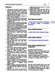
3.2 Implementation of the FE-model Linear triangular membrane elements with one integration point were used to implement the material model in DIEKA. When assuming plane stress, the matrix material effectively becomes incompressible without the capability of introducing deviatoric stresses. Contact was modelled using six node wedge contact elements. On the steel face, the normal contact stiffness was high, while on the rubber face, the normal contact stiffness was relatively low. Viscous sliding friction was used with a constant friction coefficient. The friction stress is then determined as (2) t = f Vrel where f is the constant friction coefficient and Vrel is the difference in velocity between the contact surfaces. Representing the fibre directions in natural coordinates proved a convenient way to describe the fibre distortions in the updated Lagrange discretisation. In natural coordinates, the fibre orientations remain constant, so in global coordinates these automatically conform to the elements distortions (see Figure 1).
3.1 Constitutive model In DIEKA, a material model similar to the model developed by Spencer [6] was implemented. In his work, Spencer assumes the fibres to be inextensible, while the matrix material is incompressible. These rather strong conditions were adapted for the FE simulation by assuming finite fibre stiffness in the fibre direction, and compressible matrix properties. The fibres are assumed to have no stiffness properties in other directions while the matrix response is Newtonian viscous. The stress is determined as: (1) s = − pI + S aV f1 A + S bV f2 B + Vm t ( D, a, b ) where t ( D, a, b) = 2ηD + 2η1 ( A ⋅ D + D ⋅ A) +
2η 2 ( B ⋅ D + D ⋅ B) + 2η 3 (C ⋅ D + D ⋅ C T ) + 2η4 (C T ⋅ D + D ⋅ C ) and
Figure 1: Fibre directions and element deformation
The drape simulation is displacement controlled by moving the steel mould towards the rubber mould in small steps. The modelled composite with contact elements on each side is placed between these moulds. For each displacement step, the system is solved using a predictor-corrector scheme. The simulation stops when the steel mould reaches the bottom of the rubber mould. In reality, the pressing cycle does not stop at this point. The moulds are
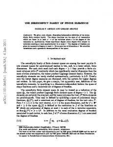
then firmly pressed together under load control to consolidate the laminate. However, it is assumed that this part of the pressing cycle does not influence the fibre re-orientation and therefore this final step is not simulated here. 4 RESULTS AND DISCUSSION To compare the geometrical and the FEM draping approach, a double dome geometry is used. The product shape consists of two coinciding hemispheres with different radii (see Figure 2).
Figure 2: Cross section of the double dome
In the FE simulation, draping was simulated using a regular rectangular mesh of 480 by 350 mm with 8360 membrane elements. The average element size was approximately 6.4 mm. As input parameters for the Satin 8H carbon fabric, the longitudinal modulus of the carbon fibres (230 GPa, Torayca T300B) was used. The roughly estimated input parameters for the PolyPhenylene Sulfide polymer matrix were: η = 100 Pa.s, η1 = 30 Pa.s, η2 = 30 Pa.s, η3 = 0 and η4 = 0. The fibre volume fraction was set at 56 %. The initial fibre directions were the same as with the geometrical drape simulation and the friction coefficient for contact was set at 33 m/(Pa.s). For the viscous response of the matrix fraction, time must be incorporated in the model. The time is derived from the press speed, which was set at 100 mm/s. The results for the FE simulation are shown in Figure 4. The CPU time used for the FE simulation was approximately 1 day on a PC with an Athlon 850MHz processor.
4.1 Simulations For the geometrical drape simulation, the highest point strategy [2] was used. The initial point in the simulation was the top of the large hemisphere. The initial fibre directions were along the main axis of the product shape and perpendicular to this direction. With a mesh size of 3 mm the result for the simulation is shown in Figure 3. The CPU time used for this simulation was approximately 1 minute on a PC with an Athlon 850MHz processor. B
D
A
C B D D
A
A
B
Figure 4: Enclosed fibre angle for FEM drape simulation (perspective and top view)
C B
4.2 Discussion D
A
Figure 3: Enclosed fibre angle for geometrical drape simulation (perspective and top view)
Here, only the predicted fibre orientations on the double dome shape (Figure 2) are compared. In the geometrical simulation, only the product is simulated since the flanges surrounding the product
have no effect on the results of the drape simulation (on the double dome). At first glance, the results do not look very similar for the geometrical and the FE drape simulation since the colouring is very different in the same region on the product. However, the enclosed fibre angles are determined by inner product calculations of the fibre directions and therefore not the colour but the deformation of the fabric should be compared. Both methods predict similar fibre orientations (and enclosed fibre angles) in region A, the outer area of the large hemisphere. Also, both methods predict the same fibre directions along the main product axes. For the outer area on the smaller hemisphere (marked with B), the geometrical draping method predicts slightly smaller fabric deformations than the FE method. The main differences occur in the concave area between the two hemispheres (marked with the dotted line). With the geometrical simulation, on both the larger and the smaller hemisphere, large fabric deformations occur (up to 40 degrees). With the FE simulation however, deformations also occur but they are much smaller (up to 25 degrees). This large difference can be explained from the geometrical draping approach. In the approach, draping starts from the top of the large hemisphere, and extends outwards from the highest point at the edge, resulting in a gradually downward moving mesh. When the mesh reaches the edge of the intersection fillet (position C), it will extend from that position onwards, up and over the top of the smaller hemisphere, resulting in a large fabric deformation at the inner area (marked with D) of the hemispheres but not at the intersection fillet itself. In the FE simulation, the fabric is not in contact with the mould surfaces in this area up until the last 20 mm of pressing when most of the deformation occurs. The latter case is the one most likely occurring in the real-life forming process. During the pressing simulation, the flanges can be seen to have a distinct influence on the composite deformation, an effect clearly not included in the geometrically based predictions. 5 CONCLUSION In the FE package DIEKA, a material model was developed and implemented, which incorporates a biaxial fabric in a Newtonian viscous like matrix material. With DIEKA and a geometrical draping method, a drape simulation for the Rubber Press Forming-process was performed. The FE simulation is expected to have the most
accurate results, especially in the concave area of the product. The geometrical method probably overestimates the fabric deformations in these areas. However, if an analysis should be performed to gain a rough indication for the fabric deformation that might occur, the geometrical method is useful for its short CPU time, especially compared to an FE simulation. 6 FUTURE WORK To model the draping process more accurately, a material model that incorporates complex fabric behaviour (locking-angle, bi-axial fabric interactive behaviour) will be developed. In the RPF-process a laminate of multiple fabric layers is pressed. Therefore, during pressing interlaminar shear deformation occurs. These deformations are presently not incorporated in this model. Finally, experiments will be performed to validate the drape simulations. References [1] T. Meinders, B.D. Carleer, H. Vegter and J. Huétink, “Recent Developments In Finite Element Simulations Of The Deep Drawing Process”, Shemet ’97, Proceedings of the international conference at the University of Ulster, April 1997 [2] O.K. Bergsma, Three-dimensional Simulation of Fabric Draping (Ph.D. Thesis), Structures and Materials Laboratory, Delft University of Technology, 1995 [3] P. de Luca, P. Lefébure and A.K. Picket, “Numerical and experimental investigation of some press forming parameters of two fibre reinforced thermoplastics: APC2-AS4 and PEIcetex”, Composites: Part A, Volume 29A, pp.101-110, 1998 [4] S.P. McEntee and C.M. Ó Brádaigh, “Large deformation finite element modelling of single-curvature composite sheet forming with tool contact”, Composites: Part A, Volume 29A, pp. 207-213, 1998 [5] K.D. Potter, “The Influence of Accurate Stretch Data for Reinforcements on the Production of Complex Structural Mouldings”, Composites, July 1979 [6] A.J.M. Spencer, “Theory of fabric-reinforced viscous fluids”, Composites: Part A, Volume 31, p.1311-1321, 2000