1. INTRODUCTION. Asynchronous circuits are becoming popular as the size and complexity of ... Tangram [3], ACK [8], and Balsa [6], represent the attempts to ...
Module-based Synthesis of Behavioral Verilog Descriptions to Asynchronous Circuits Mehrdad Najibi, Mohsen Naderi, Hossein Pedram, Mehdi Sedighi Department of Computer Engineering, Amirkabir University of Technology 424, Hafez Ave, Tehran 15914, Iran
{najibi, naderi, pedram, msedighi}@ce.aut.ac.ir
ABSTRACT
necessity.
In this paper we present a design tool for automatic synthesis of Verilog behavioral description of an asynchronous circuit into delay insensitive presynthesized library modules, using syntax directed techniques. Our design tool can also generate appropriate output to support implementing the circuit on ASICs and LUT-based FPGAs consequently rapid prototyping of the asynchronous circuit becomes readily available using the proposed tool.
Tangram[3], ACK[8], and Balsa[6], represent the attempts to fulfill this urgent requirement. Unfortunately all of these tools use their own non-standard CSP-derived languages and thus have their own shortcomings.
General Terms Design, Languages
Keywords Asynchronous circuits, Verilog, High level synthesis, rapid prototyping.
1. INTRODUCTION Asynchronous circuits are becoming popular as the size and complexity of integrated circuits increase. This flourishing popularity mostly is due to their potential ability to meet the requirements of large and complex systems. It has been proven that asynchronous systems can offer the following benefits: elimination of the clock distribution problem, modular interconnectivity, lower peak current, lower EMI, and potentially higher performance[2][10]. The major drawback of asynchronous design approach bothering its popularity is the lack of automatic design tools; therefore the development of asynchronous synthesis tools to facilitate the design process becomes a
Other asynchronous synthesis tools such as Petrify[5] , 3D[11], Minimalist [7] use a mainly STG based specification for describing the behavior of asynchronous circuits. Furthermore, they all focus on the synthesis of asynchronous controllers and can not be used to synthesize a complete circuit including controller and data-path. Recently, due to their explicit advantages, standard HDLs are targeted to be a proper alternative for CSP-derived or STG based specifications: First, by using standard HDLs, designers don’t have to learn several non-standard languages to perform an asynchronous design. Second, HDLs such as Verilog are capable of describing the circuit at any arbitrary level of abstraction. So a single language can be used in all levels of the design-flow. Finally, there are more supporting tools such as editors and simulators for standard HDLs than are available for other non-standard languages. Among HDLs, Verilog has some valuable constructs that simplify the description of asynchronous circuits. Granular concurrency and event control statement are good supporting examples. Therefore recently developed asynchronous tools may be found that use Verilog as their description language. For example Pipefitter[4] uses Verilog as its input description format, however it supports only a restricted subset of synthesizable constructs of the standard Verilog; in addition, it is not applicable for large asynchronous circuits in a reasonable amount of time. In a recently proposed synthesis tool, some extensions to standard Verilog HDL were developed to describe asynchronous circuits[9]. Although, these extensions were completely compatible to standard Verilog simulation tools, in order to use them, detailed knowledge of asynchronous circuits is required for the designer.
In this paper we propose a design tool that translates a behavioral standard Verilog description into an asynchronous circuit consisting of pre-declared and presynthesized library modules. Our experimental results show that the proposed design tool takes a reasonable amount of time for synthesis and the quality of the produced circuit is highly comparable with that of other tools in the same category. The rest of this article is organized as follows: In section 2 the synthesizable subset of Verilog constructs that is supported by our synthesis tool is described and the constructs which have been utilized to describe asynchronous circuits for the first time are discussed. In section 3 a simple example is presented to illustrate the notation and usage of these newly used Verilog constructs. Our proposed design flow is presented in section 4, and finally concluding remarks are in section 5.
2. The Set of Synthesizable Constructs To describe a broad class of asynchronous circuits at behavioral level, an adequate subset of Verilog constructs must be considered in the synthesizable set. The following are constructs of the standard Verilog which are currently synthesizable: • • • • • • • • • •
module declaration and instantiations channel, register, and parameter declarations All type of data manipulation operators Initial and always statements sequential blocks : begin-end concurrent blocks: fork-join while and forever statements if … else … and case statements Event control statements wait statements
This subset of synthesizable verilog constructs appears to be adequate to describe a broad class of asynchronous circuits at the behavioral level. Some of these constructs that are used to describe asynchronous circuits for the first time are discussed in the following subsections:
2.1 Channels Channels are the main aspect of designing asynchronous circuits. They provide data communications, buffering, and synchronization between different circuit elements. The abstract concept of channel is needed in each specification language intended to describe asynchronous circuits, so the concept of channels is added to Verilog.
In our scheme, input and output ports of each module are implicitly considered as asynchronous communication channels. In addition it is possible to explicitly indicate register variables inside a module as internal channels. Declared channels are used like registers in the description and there is not any additional restricting rule over channels. The only difference is that registers and channels will be implemented in different manners in the synthesis process. However, adding the concept of channels may lead to some confusion in Verilog descriptions. Using channels may cause deadlocks. For example reading from and writing to a specific channel in the same sequential block leads to a deadlock. To clarify such ambiguities, our design tool can detect and report simple deadlock conditions in the behavioral description. Multiple read or write accesses to a particular register or channel inside sequential or concurrent blocks are handled automatically by placing proper modules to share that resource. Our synthesis tool can also place necessary arbiter modules automatically to prevent multiple simultaneous read or write accesses to a shared resource such as a register or a channel.
2.2 Event Control Statements In behavioral descriptions of synchronous circuits, event control statements are employed as the main construct to describe timing information. It is done by specifying the actions that must be made on the forthcoming edges of a clock signal: @(posedge CLK) statement; By extending the concept of event control statements, it is possible to use them in behavioral descriptions of asynchronous circuits and specify actions that must be performed at the handshake events on a communication or synchronization channel: @(Chan) statement; The above statement can be interpreted as: “on receiving a request on channel Chan, perform the statement and then complete the handshake on the channel”. In this way, event control statements can also be used to represent handshake enclosure in behavioral description of asynchronous circuits. Expanding the concept of event control statements for channels requires a simple pre-simulation processing step for making the behavioral simulation of the circuit possible. The following variations of the event control construct are also helpful: -
@(ChanA, ChanB) statement;
-
@(ChanA) @(ChanB) statement;
The first construct can be used to specify situations where it is required to wait for receiving a request on one of the channels, ChanA or ChanB, perform the statement. The second one can be used when receiving requests on both channels are needed before performing the statement. To synthesize the event control construct we took advantage of the idea presented by Balsa to implement the Balsa select statement using FalseVariable modules[1].
a_ack-
2.3 Wait Statements
a_ack-
Wait statement constructs have been used by some previous asynchronous synthesis tools to specify the behavior of the control sections of the circuit; for example Pipefitter [4] has used them to describe the control part of the circuit in a STG-based manner.
a_req+
out_ack-
out_req-
g_ack-
However in our scheme, wait statements are used as a high-level construct which is applicable over data channels to compare their data value with a specified value until the condition is met before performing a statement, for example:
g_req+
g_req-
g_ack+ a_req-
wait (Chan >= value) statement; a_ack+
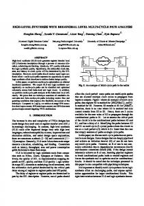
In this form, the wait statement construct can be used when required to repeat requesting data on a channel until a desired condition is met before performing statement. We have introduced a module to implement waitstatement constructs. Its schematic, STG diagram, and implementation using LUTs are shown in Figure 1 and Figure 2
g_dat+ out_ack+
g_req-
g_dat-
out_req+
Figure 1. Wait module Schematic and STG Diagram
3. Example To demonstrate the readability and flexibility of the input notation of our proposed synthesis tool and to illustrate the usage of the above discussed constructs, description of a 4-bit loadable decimal up-down counter is shown in Figure 3. The input port of the counter is a bundle which consists of up-down control, load control, and the 4-bits load data signals. On each handshake at its input channel the counter may load data, count up, or count down according to the state of these control signals. As stated before input and output ports of the counter are implicitly considered as channels, so the ports In_sigs and count will be treated as channels. To assign a value to an output channel, it must be declared as a register to preserve Verilog standard notation. Readers who are familiar with Verilog and the abstract concept of channels can understand the meaning of this sample code easily, which shows that our input notation is perfectly reasonable and readable.
Figure 2. Wait module Implementation This sample description shows that the input notation of the proposed design tool is completely compatible with the notation of standard Verilog HDL.
module updown10 (In_sigs, count); input [5:0] In_sigs; //In_sigs[5] : load //In_sigs[4] : up/down //In_sigs[3:0] : load data
implementations of asynchronous circuits on LUT-based FPGAs possible; the generated edif output contains the required mapping and timing constraints to enforce that timing assumptions of the asynchronous circuit has been met.
output [3:0] count; parameter maxcount = 9;
Standard Verilog Description
reg [3:0] count; //input & output ports are channels reg [3:0] count_reg; reg [3:0] tmp; always @(In_sigs) begin if(In_sigs[5]==1'b1) count_reg = In_sigs[3:0]; else begin case (In_sigs[4]) 1'b1://down fork if(count_reg!=1'b0) tmp = count_reg - 1; else tmp = maxcount; count = count_reg; join 1'b0://up fork if(count_reg!=maxcount) tmp = count_reg+1; else tmp = 0; count = count_reg; join endcase count_reg = tmp; end //else end // @ endmodule
Figure 3. A 4-bit loadable decimal up-down counter
4. The Design Flow The design flow for our proposed design tool is shown in Figure 4. As shown in this figure simulation can be done by using standard Verilog simulators at all levels of abstractions. Only is a simple pre-processing step needed to include the concept of channels and extend the event control statements for channels to make the behavioral simulation possible. Post-synthesis simulation is done by using the standard Verilog output netlist and simulation models of the library modules. This design tool is planned to support implementation of the circuit on ASICs as well as FPGAs. It supports ASIC Design Flow by generating standard Verilog netlist and can generate a special standard edif netlist to make
insert channel declaration
Verilog + ext.
Behavioral Simulation
High Level Synthesis
Edif For FPGA with required constrants
Pre-Synthesized Modules for FPGA
Commercial FPGA Place & Route Tool
Post Synthesis Simulation
Std. Verilog Netlist
Pre-Synthesized Modules for ASIC
Modules Simulation models
Commercial ASIC Place & Route Post P&R Simulation
Prototyping on FPGA
ASIC
Figure 4. Design Flow
5. Conclusion and Results It is possible to conceptually describe a broad class of asynchronous circuits using standard Verilog HDL. We only need to extend the standard Verilog by the abstract concept of channels and expanding the meaning of some useful standard Verilog constructs such as event control, and wait-statement constructs for channels. In the end, it must be noted that by using standard Verilog as the input description language, our design tool is very suitable for synchronous designers who want to experience asynchronous circuit design for the first time without having to spend several months on studying asynchronous design details, as well as specialists who want to design asynchronous circuits and evaluate the resulted circuits rapidly. The proposed design tool has been used to synthesize some test-bench circuits including a Reed-Solomon decoder and an 8-bit RISC core and the resulted circuits have been functionally verified. The quality of the result is satisfactory but further optimizations are still possible. As for the future work we are planning to utilize some optimization techniques which can enhance the quality of the generated circuits.
6. REFERENCES [1] A. Bardsley, Implementing Balsa Handshake
Circuits. PhD thesis, Department of Computer Science, University of Manchester, 2000 [2] C. H .K .v. Berkel, M. B. Josephs, and S. M. Nowick,
“Scanning the technology: Applications of asynchronous circuits”, Proceedings of the IEEE, vol.87, pp.223–233, Feb.1999. [3] K. v. Berkel, J. Kessels, M. Roncken, R. Saeijs, and
F. Schalij, “The VLSI-programming language Tangram and its translation into handshake circuits,” in Proc. European Conference on Design Automation (EDAC), pp. 384–389, 1991. [4] I. Blunno and L. Lavagno, “Automated synthesis of
micro-pipelines from behavioral Verilog HDL,” in Proc. International Symposium on Advanced research in Asynchronous Circuits and Systems, pp. 84–92, IEEE Computer Society Press, Apr. 2000. [5] J. Cortadella, M. Kishinevsky, A. Kondratyev, L.
Lavagno, and A. Yakovlev, “Petrify: a tool for manipulating concurrent specifications and synthesis of asynchronous controllers,” in XI Conference on Design of Integrated Circuits and Systems, (Barcelona), Nov. 1996. [6] D. Edwards and A. Bardsley, “Balsa: An
asynchronous hardware synthesis language,” The Computer Journal, vol. 45, no. 1, pp. 12–18, 2002.
[7] R. M. Fuhrer, S. M. Nowick, M. Theobald, N. K. Jha,
B. Lin, and L. Plana, “Minimalist: An environment for the synthesis, verification and testability of burstmode asynchronous machines,” Tech. Rep. TR CUCS-020-99, Columbia University, NY, July 1999. [8] H. Jacobson, E. Brunvand, G. Gopalakrishnan, and P.
Kudva, “High-level asynchronous system design using the ACK framework,” in Proc. International Symposium on Advanced Research in Asynchronous Circuits and Systems , pp.93–103, IEEE Computer Society Press, Apr. 2000. -. [9] A. Saifhashemi and H. Pedram, “Verilog HDL,
powered by PLI: a suitable framework for describing and modeling asynchronous circuits at all levels of abstraction,” in Proc. ACM/IEEE Design Automation Conference, pp. 330–333, June 2003. [10] J. Sparsø and S.Furber, eds., Principles of
Asynchronous Circuit Design: A Systems Perspective. Kluwer Academic Publishers, 2001. [11] K. Y. Yunand and D. L. Dill, “Automatic synthesis
of 3D asynchronous state machines,” in Proc. International Conf. Computer-Aided Design (ICCAD), pp.576–580, IEEE Computer Society Press, Nov.1992.