CMOS Floating-Gate Devices. Victor H. Ponce-Ponce. Electrical Engineering Department. AV. IPN, No. 2580, C.P. 07360, Mexico City, Mexico. CINVESTAV- ...
2004 1st lntemational Conference on Electrical and Electronics Engineering
Motion Detection Sensor Based on CMOS Floating-Gate Devices Victor H. Ponce-Ponce Electrical Engineering Department CINVESTAV-1PN AV. IPN, No. 2580, C.P. 07360, Mexico City, Mexico
Felipe Gomez-Castaiieda Electrical Engineering Department CINVESTAV-IPN AV. IPN, No. 2580, C.P. 07360, Mexico City, Mexico
Jose A. Moreno-Cadenas Electrical Engineerkg Department CINVESTAV-IPN AV. IPN, No. 2580, C.P. 07360, Mexico City, Mexico
Luis M. Flores-Nava Electrical Engineering Depanment CINVESTAV-IPN AV. IPN, No. 2580, C.P. 07360, Mexico City, Mexico
Abssfrrrct - This work presents a novel motion-detection sensor, based on CMOS technology. It uses floating-gate transistors to perform signal aggregation computation, as part of the centroid approximation, for 1-D real-time tracking of a regular-shape object. In fact, the object is detected from binary images, which are captured within the fietd of view of this sensor. The analog-weighting process for the spatial column-components, in the associated algorithm, is realized by using MOS transistors operating in the triode region. Only binary images are considered, even though image information is sacrificed, faster operation speed and increased functionality is obtained. The motion-detection sensor was fabricated using a 1.2pm, n-well, CMOS process. The design contains a 17x18 cell-array with a fill-factor is 35.6%. The electrical analysis supported by PSpice of this initial CMOS integrated circuit, demonstrates that its extension to a larger prototype for robotic applications is attractive.
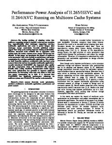
2. SYSTEM ARCHITECTURE The global architecture for the (MDS) is introduced in Fig. l(a). The system approach consists of a 17x18 cellarray of variable threshold photogate-type active-pixels sensors. Each pixel delivers a binary voltage (0, W ) ,that is coupled capacitively via the in-pixel column capacitor C,, with the floating-gate of a NMOS transistor. This transistor produces a voltage signal VsFi, representing nearly the average-sum of the binary voltages, Vouc supplied by the pixels of an entire column. This averaged-voltage contributes to evaluate the size of the columns in the histograms on the respective coordinate-axis, The histograms are next processed by a weighted-voltage multiplier circuit. " m l
bbmmi
1 , 1NTRODUCTlON A new category of devices, known as smart-sensors, have
been reported recently in many intelligent systems. The design of these devices integrates on a single chip, image sensor elements and information processing circuits. This category of sensors, which are information-oriented systems, obtain the best perFormance from sensors and also make the sensing and processing information tasks more compact. The design of these devices is generally targeted for a specific application, where speed, dynamic range, size, power dissipation and system integration are important issues to take into account. Some examples have been introduced in the literature [I], that attempt to track in real-time the centerof-mass of a regular object using CMOS floating-gate transistors, or ordinary CMOS-based circuits [2][3]. In this work, binary images are captured and their centerof-mass computation (COM) is partially processed on the same chip, using clock-controlled floating-gate CMOS transistors (FGMOS) [4]. This technique eliminates the intrinsic charge that is acquired and stored in the floatinggate terminal during the fabrication process of the circuit. The motion detection sensor (MDS) generates the histograms by projecting the number of pixels in on-state, for each cohmn of the pixel-cell array, on the respective coordinate-axis in response to a certain visual scene.
0-7803-8531 -4104/$20.00 02004 IEEE
206
(b) Figure 1. (a) Block level presentation of the MDS and (b) Schematic diagram.
produced at the source terminal of the corresponding floating-gate source follower transistor (FGSF) and is given by (I), where gfFsF is the transconductance parameter of the associated n-channel transistor in the FGSF and gLoAD represents the active-load transconductance, respectively. VFGi is the potential induced in the floating-gate terminal in the respective FGSF, by a column of pixels, and is given by
3. PIXEL CIRCUIT A schematic of the baseline pixel design is introduced in Fig. 2(a), and is partially based on early structures introduced in literature [5]. The photogate is separated from the two-input floating-gate CMOS inverter (FGMI) by a transfer gate (MX). The pixel uses a reset transistor (MRD), for pre-charging the floating-capacitor array ( C F ~ )formed , by the source and drain terminals of MRD and MFl, and also by the right-side terminal of MX (FD), where the conversion to voltage takes place. Also, it has been placed, three transistors (MFI, MF2 and MF3) on the pixel. They are used to discharge the floating-gate of FGMI. An ordinary CMOS inverter (MP y MN) reinforces the binary voltage level provided by FGMl. A. Operation Firstly, a brief pulse is applied to MF1, MF2 and MF3, for discharging the floating-gate of FGMI. Next, capacitor Cm is preset to approximately 3.8V by pulsing the gate of MRD. Then VG goes high (W), starting a signal-charge integration period (tllil).During signal integration period ( 4 0 ~ s ) electrons ~ are collected under the surface of the photogate. At the end of this period, MX is pulsed on and electrons are transferred to the FD, changing its surface potential. The potential there is read by Cl, A reference voltage Vu, is used to change the intrinsic inverter switching-point of FGMI.
(2).
j-I
In (Z), C,, denotes the in-pixel column capacitor. Voltage Vouois the binary voltage delivered by the pixel in thej-row, and m=17. Voltage VsFl represents the magnitude of the icomponent of the histogram generated at the i-column of pixels and is proportional to the summation of the pixels in on-state (5V). Voltage IfsFr will start generating a valid voltage level for a potential in the floating-gate, which hlfills VFG,> 2AV+V* setting 2AV+Vthg13 6 as the minimal voltage required by each cascode current source in all the FGSF for operation in the saturation region. ,___________________-----------------*--*-----------~--.----R. Muhplicution for histogrunis 1 PRoTDOxra PIxnIUecl -wd The proposed column multiplication circuit requires a YG ez i: three-phase non-overlapping clock scheme. For each column ! Q of pixels (i=l,2,. ..,I E), and during the first phase (41 active), (see Fig. 1 (b)) voltage Vsfiis applied to the gates of MN, and MD,, contributing to the generation of the currents SJNU and SIDE. As shown in Fig. 3, these currents are converted to voltage and sampled in C J and ~ C2+ respectively. Next, during $2, V2com is applied to the gate of MN, and MD,. Then, SINU and SIDE are converted to voltage and sampled in C r p and C2&. During the third phase ($3 active) the difference of voltages stored in C,#, and CA@is computed and stored in Cs, (where x, stands for I ,2). This difference is the aggregated multiplication of the corresponding applied drain to source voltage in MN, and MD,, times the weighteddifference voltage k.AVsFt-V2Com). I
k
y y
I I
, I
Figure 2. (a) Schematic circuit of the pixel element, (b) Timing diagram for the MDS operation.
4. MULTIPLIER CIRCUIT
A. Generation of Itistogrants In Fig. I (b), we present the proposed circuit for the pixelcolumn weighted-voltage multiplication process. In each column of pixels, a signal-voltage VsFj, (i=l,2,..,18) is
207
Figure 3. Off-chip multiplication circuit for the MDS
Where k is the transresistance factor of the current-tovoltage conversion stage, p is the transconductance of MNi and MDi, and n=18. Then, as the source terminal of each FGSF is connected to a common node, see Fig. 1 (b), current sum is performed resulting in the following set of equations.
(3) n VDEN
= k * P * VDL,
kSFi
- VREFl)
(4)
i=l
Finally, the COM computation can be calculated as follows.
Figure 5. Complemented-buffered output measured response of the pixel under a charge-integrationperiod of 40ps, case (a) For P=O mW/cm', and case (b) For a FO.146 mW/cm2of illumination, and V,=3.85V.
5. RESULTS A. Pike/ transient respoase
For this test, we used a photocharge integration period of 4 0 p and an illumination of P=0.146mW/cm2. Then a potential decrease in FD, &' = 2.4V, from reset level (YWx,,=3.8V)is calculated and measured. Fig. 4(a) shows, a PSpice simulation of the transient response for the complemented-buffered output of the pixel structure {NOT( Voutj)]. Without illumination, a low-output level in the pixel, at the onset of TX signal, is found as expected. Next, in Fig. 4(b) an illumination of P=O. 146mW/cmz fiom a fluorescent-lamp light source is applied. The lowering in the floating-diffusion potential is now enough to change the output-state of FGMI, therefore a high-level output is achieved at the onset of TX signal. Measured response is shown in Fig. 5 (a-b).
5w
B. Inverter switchiizg-point programming it the pkel In Fig. 6 , we present a PSpice simulation of the inverter switching-point ( Vsp) programming feature for the proposed pixel structure, as a function of Vu. If we consider a certain voltage decrease from reset level, i.e., sV=1.2V, sensed at FD, and a Vu =2.5V, pixel changes its output to off-sate, but remains in on-sate for a v ~ 3 . W As . a result, if higher illumination conditions are present, the intrinsic threshold of the two input floating-gate inverter can be increased to take into account for higher voltage changes at FD. Time integration of light can also be used to cope with different levels of light illumination, but the rms noise increments produced in the pixel for longer integration periods, must be considered. Therefore optimal values for Vu and tintmust be proposed for a good speed and contrast quality in the COM processing. C. Colurtrn niultiplicatioit process A simulation of the voltage-weighted multiplication response for all the columns appears in Fig. 7(a). Horizontal axis represents the number of pixels in on-state. The trace labeled as COLI, at the bottom place in the graph, is the response contribution for the first column of pixels for the numerator term, at the node VWM. The second trace, from the bottom place, corresponds to the second column, and so on for the rest.
2w 5 OV
5w
4.0V
2 N
W
2w
6
ov
Figure 4. Complemented-buffered output simulation orthe pixel stmcture for a charge-integration period of 4Op, K,=3.85V, case (a) For P=O mW/cm2, and case (b) For a P=O.146 mW/cm2 of illumination.
ov
05v
VWGMI)
1ov
15v
2.0v
25v
30v
35v
40v
45v
V(V0UTJ)
Figure 6. DC-Analysis for the pixel, Vu swept from 2.W to 3.7".
208
51
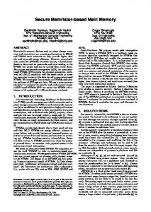
D. Center-of-mass simulation For this test, a I-D COM processing was carried-out by sweeping the MDS in time, with a delta-like histogram scene. The COM simulation response of the system was satisfactory and is introduced in Fig. 7 @). In this case, COM position is monitored as a voltage level in the vertical axis. 6. PROTOTYPE 1NTEGRATED CIRCUIT The MDS described in this report was fabricated using double-poly, double metal CMOS process with 1.2pm design rules, using MOSIS services (Run-T39TAM). The microphotography of the silicon chip is shown in Fig. 8 and general specifications are summarized in Table 1. 7. CONCLUSION We have designed a test chip for detecting binary images and computing in real-time the COM position in l-D, of regular objects. The chip is expected to perform 10x103 COM operations per second, therefore speed and direction of movement of an object, relative to the coordinated-axis, can be calculated. This initial integrated circuit may easily expand to a 2-D COM scheme by incorporating in each row of pixel-circuit a multiplication stage. Higher sensor resolution, like a 128x128 cell-array size, is considered as a starting point for practical robotic visual-coordination tasks. This cell-array size can be achieved if we could afford larger silicon realestate with another advanced technology process, with extra metal layers to facilitate routing, as we have used metal 2 for shielding active areas from light. Center-of-mass measurements have not been performed by the time of the submission of this paper. However, they will be presented in due course.
TABLE I GENERAL SPECIFICATIONS Pixel structure Full well capacity FD capacity Pixel noise Dynamic range (pixel) Voltage conversion Fill factor Die size
I38 Me230 Ke93 e120 dB 10.6 pV/e35.6 Yo 4 m2
Chip Power consumption
XOmW
Figure 8. Microphotography of the MDS using double-poly, double metal CMOS process with 1.2pm dcsizn rules.
8.REFERENCES [ l ] N. Yu, T. Shibata, and T. Ohmi, “A Real-Time Centerof-Mass Tracker Circuit Implemented by Neuron MOS Technology,” lEEE Transactions on Circuits and S?,stenis-ll: Analog and Digital Signal Processing, vol. 45, No. 4, pp, 49.5-503, Apr. 1998. [Z] R. Meitzler, K. Strohbehn, and A. Andreou, “A Silicon retina for 2-D position and Motion Computation,” Proc. IEEE Int. Sjmposium on Circuits and Systems, pp. 2096-2099, 199.5. [ 3 ] Bums, R., Shah, J., Hong, C., Pepic, S., Lee, J., Hornsey, R., and Thomas, P., “Object Location and Centroid Techniques with CMOS Active Pixel Sensors,” IEEE Transaction on Electron Devices, vol. 50, NO. 12, pp. 2359-2377, 2003. [4] K. Kotani, T. Shibata, M. Imai, and T. Ohimi “Clockcontrolled Neuron-MOS Logic Gates,” IEEE Tran. on Circuits and Systerns-11: Analog and Digital Signal Processirig, vol. 45, No. 4, pp. 5 18-522, I 998. [5] S. Mendis, S. Kemeny, R. Gee, B. Pain, C. Staller, Q. Kim, and E. fossum, “CMOS Active Pixel Image Sensor for Highly Integrated Imaging Systems,” IEEE Journal of Solid-State Circuits, vol. 32, No. 2, pp. 187197,1997.
Figure 7. ( a ) Voitage-weighted based column multiplication simulation for variable number of pixels in on-state (b) COM-coniputation simulation applying a delta-like histogram swept for the 18-input MDS.
209