Neural Network Pattern Recognition for Robust and Highly Precise TCP Trajectory Measuring for Industrial Robots Adolfo Bauchspiess Universidade de Brasília GRACO/ENE/UnB - Grupo de Automação e Controle 70910-900 - Brasília / DF – BRASIL
[email protected]
Bernhard Wagner, Peter Benker Universität Erlangen-Nürnberg IRT – Institut für Regelungstechnik 91056 – Erlangen – GERMANY
[email protected]
Abstract This paper presents a procedure for the robust and highly precise TCP (‘Tool Center Point’) trajectory measuring for robotic manipulators equipped with an “eye-in-hand” CCD-camera. The measuring procedure is based on the evaluation of a video sequence as the robot TCP is moved over a reticulate pattern. Analytical computer vision techniques are compared with results obtained by an artificial neural network approach. Despite the greater computational effort the NN approach can better compensate for illumination variations, lens geometrical distortion, incomplete patterns and picture noise. Experimental results of the implementation on a CCD-camera guided hydraulic robot are discussed. Keywords: Computer Vision, Neural Networks, Robotics, Photogrammetry.
1. Introduction Robotic manipulators are being used in many industrial applications for a long time, among other arguments, to improve quality, security and precision. If they are equipped with sensors it is possible to automate industrial processes in an "intelligent manner". This is actually the object of intense research effort in the field of Artificial Intelligence (AI): to build machines that consider the information captured from the environment in which the robot is inserted in a proper (intelligent) manner[1]. To guarantee the quality of robot automated processes it is necessary to have an on-line procedure to monitor the real robot trajectory, compare it with the programmed trajectory considering eventual work-piece deviation and act accordingly in the closed loop using an appropriate control strategy. The use of the robot joint variables, as measured by resolvers or encoders, to obtain the TCP position using the direct cinematic transformation is, however, often not sufficiently precise, due to error propagation. In a priceprecision compromise, commercial robots are build with relatively high mechanical tolerances (dead zones, back-slash, arm and driver flexibility, friction, etc.), so that the repeatability of “teach-in” robot
positions high is, but TCP positions that are defined in the global coordinate system can be reached with only poor precision. Instead of building stiffer, and so more expensive robots, a practical approach would be to use a TCP sensor. This is the situation when using sensor-guided robots, where the task trajectory is obtained “on-thefly”, i.e., there is no a priori teach-in procedure. In this case the sensor system that is used to capture the trajectory can also be used to close the feedback loop, by evaluating additionally the TCP deviation from the captured task trajectory. This can give high precision because the system works “locally”. Mechanical tolerances, as mentioned above, are compensated implicitly. At this point, however, there is a relevant open question, ‘which global trajectory the robot took really?’ or ‘how can the control strategy be evaluated?’ (The local measures give only limited performance insight). To answer these questions it is obviously necessary to have a global TCP trajectory measuring system. Other frequently encountered situation is that most commercial robots, for security reasons, give no access to the internal joint measures when performing a programmed task, e.g., the S3 from ABB [4], despite the fact that this values are available internally for the S3 robot controller. This
restricts particularly the use of these robots for research purposes. In the field of Artificial Intelligence (AI) several techniques were developed in the past decades based on processes/behaviors that occur in the nature [1],[2],[3]. So neural networks were inspired in the connectionist paradigm of parallel signal processing that occurs in the brain. Artificial Neural Networks can be very different from their inspiring natural counterparts. The efficiency of parallelism and learning capability are the interesting aspects. For applications in the area of automatic control, e.g., the objective is giving a machine the capabilities of an experienced (expert) worker [1]. In this paper two procedures are presented to obtain the TCP trajectory using a pattern recognition algorithm for robots equipped with eye-in-hand CCD cameras. A classical, analytical computer vision technique and a Neural Network based approach. The tracking of a line cross or of a quadrate as the camera moves over a reticulate pattern can give information of the global deviation of the TCP from the previous evaluated position. Here only the case of a robot moving parallel to a work-piece plane will be considered, i.e., only the (x, y) position and the ϕ orientation of the actuator will be determined. This, however, reflects the situation that occurs most frequently in the industrial practice (leather cutting, gluing, seam tracking welding etc.). For the classical pattern recognition, a algorithm was used, that tracks geometrical features on the image for the TCP relative deviation and a neural network based procedure that was intended to give a greater robustness against illumination variations, lens geometrical distortion, incomplete patterns and picture noise. The proposed procedure was implemented to measure the TCP of a hydraulic manipulator guided by a CCD-camera, where it was shown that the neural network approach reduces the sensibility of the measuring process significantly.
relation between world coordinate system and the camera coordinate system is determined by the joint angles and the respective arm lengths, see Figure 2 .
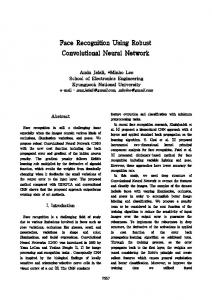
Figure 1 - 2 DOF eye-in-hand robot moving parallel to a reticulate pattern. The actual CCD image is shown the upper left corner.
Figure 2 - Coordinate systems for a 2 DOF axial robot.
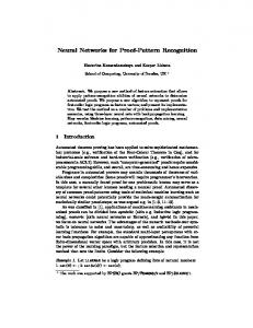
In this work we will consider the camera center as the TCP. When the robot’s TCP is moved over the fixed reticulate a unique image sequence will be captured by the CCD camera. If the frame rate is high enough or conversely, if the TCP velocity is accordingly slow, then a geometrical characteristic of the reticulate pattern, such as a line cross or the center of a quadrate, can be tracked through the image sequence, Figure 3 and Figure 4.
2. Pattern recognition TCP measuring Considering that a 2 DOF (Degree of Freedom) robot equipped with an eye-in-hand CCD-Camera is moving parallel to a reticulated plane, the camera would capture an image with a determined position and orientation of the reticulate in reference to the camera coordinate system. The reticulate plane can be obtained using structured light techniques or, for research purposes, the reticulate can be a laser quality paper print attached to a trajectory plate mounted parallel to the TCP trajectory plane, as shown in Figure 1. The optical lens characteristics, the distance of the reticulate plane to the CCD plane and the CCD pixel resolution determine the precision of this measuring arrangement. For a 2 DOF robot the
Figure 3 - Image sequence corresponding to the first 4 TCP positions in Figure 1. A reference track quadrate to determine the TCP position and orientation is marked.
For a discrete time intant k the TCP xH = [xH yH], can be obtained from the absolute, world coordinate position of a reference line cross xLK,W = [xLK,W yLK,W], added to the transformed center point of the image [xcenter,K ycemter,K] relative to this reference line cross in camera coordinates ∆ LK , K : x H = x LK ,W + TKW ∆ LK , K
(1)
x center , K − x LK , K where ∆ LK , K = y center , K − y LK , K
(2) w2 K
and the rotation matrix is given by − as cos w2 K TKW = − a ssinw2 K
− a ssinw2 K − as cos w2 K .
− wαβ = − wαβ + π / 2 − w − π / 2 αβ î
q = 0,3 q =1
(4)
q=2
(3) β , wαβ = î α,
The angle w2 K = w2 − π , is shown in Figure 5. a s is given from the geometrical dimensions of the camera arrangement.
q = 0,1 q = 2,3
Figure 6 - Orientation angles in CCD coordinate system.
Figure 4 – TCP as camera center and two positions of the camera over the reticulate pattern.
As the TCP is moving, line crosses will get out the image, so it is necessary at times to times to exchange the reference line cross used in the proposed algorithm. This can be accomplished considering the other three crossing points that are nearer to the camera center, and taking the point with the smallest Euclidian distance. Considering different trajectory plane distances, the worst case for this decision is shown in Figure 7
As the reticulate pattern image is the same if the camera is turned 90°, it is necessary to track the quadrant information in order to obtain the correct TCP information. A variable q=0,1,2,3 can be used for this purpose, as shown in Figure 5. x q=2
q=1
W
Figure 7 - Worst case for reference line cross exchange.
Arm 2
w
2
q=3 w
y
W
Arm 1
When the reference line cross is changed x LK ,W = x LK ,W y LK ,W must be actualized in order
q=0
to get the right TCP, x H = x H − [d
w
2K
y
[
x 1
]
0] , Figure 8 T
H
H
Figure 5 - The quadrant variable q.
From eq. (1) it can be seen that the robot’s TCP can be determined from the position of a line cross in the reticulated CCD image. As the proposed algorithm works with local information, it will be assumed, for the global TCP determination, that for k = 0, the initial time, the reference line cross and the quadrant (or the angle w2 K = w2 − π ) are known. From the angles α or β (Figure 6) of the reticulate in the camera coordinate system, the TCP orientation is determined using the quadrant information:
Figure 8 - TCP correction from local quadrate deviation.
3. Classical Computer Vision Approach To determine the TCP from the reticulate pattern we can track a line cross in the image sequence. In each image we can start from P0, the center of a quadrate in the former image, Figure 9 From there the points P1 and P2 on two perpendicular line will be searched in the actual image (as gray limiar value).
read as (x,y) positions and then each robot position is simulated, Figure 1. In the upper left corner, the CCD image that would be obtained for the corresponding robot position. Figure 12 shows the pattern recognition obtained TCP cartesian errors, when compared with the original trajectory points. It can be seen that a very good sub-pixel precision is obtained. By a line width of 2.5 pixel the obtained mean error is 0.0149 of a pixel. By a line width of 2 pixel the obtained error was only 0.0066 of a pixel.
Figure 9 - Line cross search considering former image.
From points P1 and P2 several pixels of each line will be read and can after be used to determine the line parameters by linear regression, Figure 10.
Figure 11 - Cartesian error of the evaluated trajectory.
4. Neural Network TCP determination
Figure 10 - Line pixel read procedure.
From the parametric representation of each line y = bxyx + axy it is easy to calculate the line crossing point. The line parameter are obtained by the least square method as: a xy = ~ y − bxy ~ x, (5) ~ 1 with x = n~
n
∑ i =1
~ gi x i ,
~y = 1 n~
n
∑ i =1
g~i yi
4.1 Training data preparation (6)
The fictitious “point” number here used, in virtue of the gray value weighting, is defined as: n~ =
n
∑ ~g
i
i =1
~ , gi = 255 − gi
The motivation for using NN in this work is to give the system a greater robustness in TCP measuring, when compared with classical approaches. In order to train the NN a sequence of training patterns must be generated. These patterns should be rich enough in information to permit the NN to capture the non-linear mapping between input and output. Concretely this means that almost every situation that can occur in a path following must be presented to the NN. Furthermore, noise data must be presented to the net if robustness is to be expected.
(7)
Equation (5) is not the only possible way of using the pixel information to obtain sub-pixel precision of the line parameters [11]. The results presented in this work where obtained using 120 pixels per line on both sides of the line cross, as indicated in Figure 10.
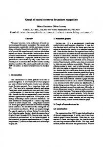
The task of the NN is from each image frame to calculate three parameters: x, y and ϕ of the TCP. Giving the whole image as input for the NN is too wasteful. A smarter solution is to reduce the input data by a convenient analytical pre-processing of the image. In Figure 12, starting from the picture center a radial search is shown that gives 16 points as representative for the position and orientation of the quadrate in the camera coordinate system.
3.1 Simulation results A graphical software environment for sensor guided robots was developed [5]. Trajectories are
Figure 12 – Input data preparation for the NN.
After some experimentation with these input preparation it has been found that it is better to use another step in the input data preparation: 1 – Start using 4 points searched radially to obtain a rough estimate of quadrate center in the actual frame. 2 – Radial search starting from the estimated quadrate center to catch the 16 NN input data points.
In the search procedure a threshold value is to be defined which separates the white background from the black reticulate lines. This threshold value should be adapted in the real application to take care of illumination variations.
4.2 Neural network topology A back-propagation neural network with 16 inputs, one hidden layer with 20 neurons and 4 output neurons has been used. In the first experiments only 3 output neurons have been used (Neuron1: x, Neuron2: y, Neuron3: ϕ). But this lead to difficulties due to a discontinuous output despite only continuous inputs (smooth robot movement) were used. This situation occurs when the reference quadrate turns around 90°. Images for ϕ = -44.9° and ϕ = +44.9° are almost identical. To face this problem 4 outputs were used: Neuron1: x, Neuron2: y, Neuron3: sinϕ and Neuron4: cosϕ. From the last two outputs the angle ϕ can always be uniquely reconstructed.
4.3 Simulation Results The NN were implemented using the Bavarian Research Center for Knowledge Based Systems FORWISS neural network development program FAST (FORWISS Artificial Network Simulation Toolbox) [12]. This program does not have a graphical user interface and is so a very portable ANSI C implementation, that runs on PCs and Unix Workstations. FAST trained nets can generate as C – implementation code that can be embedded in other target application. The image sequences for the neural network algorithm were generated by a graphical C++ software environment for sensor guided robots [5]. Trajectories are read as (x,y) positions from ASCII files and then each robot position and correspondent CCD-image are calculated and shown in the simulation area of the presentation window. A total of 27 different Net/Training pattern sets were studied, reflecting different TCP trajectories, orientation angles, starting point, preprocessing etc. The best results for N20 and N26 are summarized in Table 1, [8]. N26 uses the two step pre-processing of the input data, leading to better results when compared with N20, where only one step pre-processing has been used. In this simulations it was assumed that each pixel have the dimension 1mm x 1 mm. In the
implemented CCD guided hydraulic robot the vision field was only 22,5 mm, which gives for the employed 128 x 128 pixel CCD-camera a pixel width 0.0391 mm. So the obtained precision is very high, much better than most mechanical positioning systems can deliver. Table 1 – Mean error for two NN/training configurations.
TCP mean error (mm) Without noise Image noise Input data noise Noise with σ = 1mm Noise with σ = 5mm Noise with σ = 20mm
N20 0.6 0.9 0.7 0.7 0.7 0.8
N26 0.05 0.06 0.3 0.04 0.15 0.5
Figure 13 of (Part 1) showed the obtained TCP cartesian errors, for the conventional computer vision based algorithm using line cross tracking. By a line width of 2.5 pixel a mean error of 0.0149 of a pixel has been obtained. And by a line width of 2 pixel the obtained error was only 0.0066 of a pixel. So the precision of the analytical method is, as obtained by simulations, better than the obtained by the Neural Network approach. But the expectation is that the classical method will often fail, when, for example, a noise corrupted incomplete reticulate is to be processed. It should also be considered that the classical approach in (Part 1) uses 120 pixel gray values for each line to determine the line cross, whereas the NN input data pre-processing uses only 4 pixels on each of the four lines involving the last found quadrate center. If a similar amount of input data is used by the NN it would be expected that similar sub-pixel precision would be obtained.
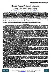
5. Experimental Results To verify the theoretical results, it was used a hydraulic manipulator guided by a CCD-video camera [5], as shown in Figure 13. The robot joints where decoupled and linearized using non-linear techniques [9]. Furthermore to enhance the trajectory tracking precision a Following Model Predictive (FMP) Servocontroller was used [5]. The non-linear controller was implemented on a DSP32C digital signal processor in a PC-486 host. The image interpretation and the predictive servocontrol was carried out by another PC-486 with a DSP16A and a DSP32C [10], compare with Figure 14. In this work a fast Dalsa® Inc. CCD camera with 128x128 pixel and a dot clock free programmable up to 16 MHz was used, which can thus work as fast as 1000 Frames/sec. To verify the influence of digital pre-filtering of the image in order to enhance the TCP determination, diverse digital filters where employed. But analysis of the results showed that the
linear regression used in the proposed algorithm is by itself the best filter for the TCP determination [7].
Figure 13 - CCD-camera guided hydraulic manipulator.
programmed and real TCP trajectory, a crucial factor to guarantee quality in automated robot cells, can so be on-line monitored. The next step in this research line would be implement the Neural Network based TCP measuring algorithm on a Transputer based parallel processing hardware available in the GRACO Laboratory in Brasilia/BRASIL. There a 6DOF ABB welding robot is already equipped with a CCD camera and the interfaces between the Transputer and the robot S3 controller are being developed. With the availability of this TCP measuring system a bottleneck in the use of the ABB robot for research purposes will be removed, enabling the use of sophisticated and highly precise path tracking algorithms, e.g., the FMP predictive servocontrol [5]. Acknowledgements This work was supported by CNPq. The authors wish to thank Universität Erlangen-Nürnberg and Prof. Dr.-Ing. W. Bär under whose orientation this work was carried out.
Figure 14 - Hardware used in the implementation.
An interesting test was to maintain the robot in a fixed position and evaluate the TCP, Figure 15 (only x coordinate, the y coordinate has a similar error pattern). In these measures it can be seen that despite noise, variations in the illumination, robot imprecision etc., there is a small variation in the obtained TCP value.
X/mm
Bildanzahl
Figure 15 - Measured X coordinates for a fixed TCP.
6. Conclusion In this paper it was shown how pattern recognition can be used to capture the TCP trajectory of industrial robots. In this work a reticulate pattern was used and from the local position and orientation of a line cross in each image the global TCP trajectory has been reconstructed. The implementation of the algorithm to a CCDguided hydraulic robot demonstrates the practical robustness and precision of the proposed approach. The dynamic tracking error that occurs between
References [1] Gewarter, W. B.: Intelligent Machines, Prentice Hall, New Jersey, 1985 [2] Görz, G.: Einführung in die Künstliche Intelligenz, 2. ed, Addison-Wesley, 1995, in german [3] Zell, A.: Simulation Neuronaler Netze, AddisonWesley, Bonn, 1995, in german [4] ABB-S3 User Manual, ABB, 1992 [5] Bauchspiess, A.: Prädiktive sensorgesteuerte Bahnführung von Handhabunssystemen. Dissertation, Uni Erlangen-Nürnberg, 1995, in german [6] Bauchspiess, A.: Servocontrole preditivo de robos guiados por sensores. Anais do XI CBA, pp. 17151720, Sao Paulo, 1996, in portuguese [7] Neumeier, T.: Bewegungserfassung eines Industrieroboters mit einer CCD-Kamera am Handpunkt. Studienarbeit, Universität Erlangen-Nürnberg, 1994, in german [8] Benker,P.: Der Einsatz von Mustererkennung mit neuronalen Netzen zur Lageerfassung für enen Roboter. Studienarbeit, Universität ErlangenNürnberg, 1995, in german [9] Erhard, N.: Zum Aufbau eines hydraulisch angetriebenen Handhabungsgerätes mit biegeelastischer Mechanik und dessen Regelung basierend auf Methoden der Exakten Linearisierung. Dissertation, Uni Erlangen-Nürnberg, 1995, [10]Lebender, J.: Realisierung einer Konturverfolgung für einen hydraulischen Roboter mit CCDKamera.Diplomarbeit, Universität Erlangen-Nürnberg, 1994, in german [11]Haberäcker P.: Digitale Bildverarbeitung/ München: Hanser Verlag 1991, in german [12]Arras, M.K.; Protzel, P.W.: FORWISS Artificial Neural Network Simulation Toolbox, V1.0, Bavarian Research Center for Knowledge-Based Systems, FORWISS, Erlangen, Germany, 1993