Journal of Computational and Nonlinear Dynamics. Received February 27, 2017; Accepted manuscript posted August 1, 2017. doi:10.1115/1.4037416 Copyright (c) 2017 by ASME
Non-Fragile Fuzzy Output Feedback Synchronization of a New Chaotic System: Design and Implementation
ed ite d
A. Azarang1, M. Miri1, S. Kamaei1, M.H. Asemani2,* 1
Department of Communication and Electronic Eng., School of Electrical and Computer Eng., Shiraz University, Shiraz, Iran
2
Department of Power and Control Eng., School of Electrical and Computer Eng., Shiraz University, Shiraz, Iran
py
Abstract: A new three dimensional chaotic system is proposed with four nonlinear terms which include two
Co
quadratic terms. To analyze the dynamical properties of the new system, mathematical tools such as Lyapunov exponents, Kaplan-York dimensions, observability constants and bifurcation diagram have been exploited. Results
ot
of these calculations verify specific features of the new system and further determine effect of different system
tN
parameters on its dynamics. The proposed system has been experimentally implemented as an analog circuit which
sc rip
practically confirms its predicted chaotic behavior. Moreover, the problem of master-slave synchronization of the proposed chaotic system is considered. To solve this problem, we propose a new method for designing a non-fragile Takagi-Sugeno (T-S) fuzzy static output feedback synchronizing controller for a general chaotic T-S system and
Ma nu
applied the method to the proposed system. Some practical advantages are achieved employing the new nonlinear controller as well as using system output data instead of the full-state data and considering gain variations because of uncertainty in values of practical components used in implementation the controller. Then, the designed controller has been realized using analog devices to synchronize two circuits with the proposed chaotic dynamics.
ed
Experimental results show that the proposed non-fragile controller successfully synchronizes the chaotic circuits
pt
even with inexact analog devices.
ce
Keywords: Chaotic system; T-S fuzzy controller; Non-fragile controller; Synchronization; Kaplan-York
Ac
dimensions; Circuit implementation.
*
Corresponding author: email:
[email protected].
1
Downloaded From: http://computationalnonlinear.asmedigitalcollection.asme.org/pdfaccess.ashx?url=/data/journals/jcnddm/0/ on 07/29/2017 Terms of Use: http://www.asme.or
Journal of Computational and Nonlinear Dynamics. Received February 27, 2017; Accepted manuscript posted August 1, 2017. doi:10.1115/1.4037416 Copyright (c) 2017 by ASME
1. Introduction Chaos theory is a field of mathematics which studies the behavior of dynamical systems that are highly sensitive to initial conditions [1]. Chaos can be observed in the dynamic behavior of many
ed ite d
different engineering systems, such as weather and climate, economical, mechanical, biological, electronics and optoelectronics systems [2-7]. Study of the chaos is a subject of consideration because of its importance in detecting and controlling the dynamic behavior of the
py
abovementioned systems. Furthermore, it provides possibility of interesting applications such as
Co
secure communication and image encryption based on synchronization of chaotic electronic and optoelectronic systems [8, 9]. As an expanded example, chaotic systems have play an important
tN
ot
role in military applications, due to its interesting properties in hiding information and decrease the dependency of information. Moreover, in biology systems, chaos property can be used in an
sc rip
effective way to predict and control the irregular heart activity which is a crucial application in daily life of humans.
Ma nu
Since the first specific explanation of chaos in dynamic behavior of a physical system by Lorenz in 1963 [10], many chaotic dynamic equations for modeling behavior real systems in different fields of science and engineering have been discovered and studied [11-15]. Recently,
ed
researchers are finding chaotic systems with more complexity including hyper-chaotic systems
pt
[16, 17] and fractional order chaotic systems [18, 19].
ce
Among different physical systems with chaotic dynamics, electronic circuits have some unique
Ac
properties which have made them popular. For a wide variety of nonlinear dynamic systems, an equivalent electronic circuit can be designed which obeys the same set of equations as the original system. Using this equivalent electronic circuit, the dynamic behavior of the original system can be observed and proper methods can be developed for controlling its behavior. Chaos
2
Downloaded From: http://computationalnonlinear.asmedigitalcollection.asme.org/pdfaccess.ashx?url=/data/journals/jcnddm/0/ on 07/29/2017 Terms of Use: http://www.asme.or
Journal of Computational and Nonlinear Dynamics. Received February 27, 2017; Accepted manuscript posted August 1, 2017. doi:10.1115/1.4037416 Copyright (c) 2017 by ASME
was observed in early electronic circuits such as vacuum tube based Van Der Pol oscillators as an undesirable effect [20], but the first electronic circuit that was intentionally designed to operate in chaotic regime was proposed by Chu in 1983 [21]. Following that, many chaotic
ed ite d
circuits with different design and dynamic behavior were proposed. For instance, a new hyperchaotic system and its circuit implementation was introduced in [22]; and a fractional-order Newton-Leipink chaotic system and its circuit implementation was proposed in [23].
py
In this paper, we first propose a new three-dimensional chaotic system. The dynamics of the new
Co
system consists of ten terms including four nonlinear terms. Unlike the generalized Lorenz system (GLS) and most of the Lorenz-like systems, the proposed system includes two quadratic
tN
ot
terms. Dynamical properties of the proposed system are investigated through mathematical analysis including calculation of Lyapunov exponents and Kaplan-York dimensions [24],
sc rip
extraction of bifurcation diagram by varying different parameters of the system. These dynamical properties are then compared against properties of well-known three dimensional
Ma nu
chaotic systems such as Lorenz, Chen and Lu systems. These investigations reveal some specific features of the new system including relatively large Kaplan-York dimension, coexistence of attractors, and different chaotic attractor compared to those of abovementioned systems. These
ed
observed specifications motivate consideration of the proposed system as a remarkable new
pt
chaotic system.
ce
As a physical example of the new chaotic system, an equivalent analog circuit realizing the same
Ac
set of the new proposed differential equations is designed and experimentally implemented. Measurement on the mentioned circuit shows good agreement between the proposed system and designed equivalent circuit.
3
Downloaded From: http://computationalnonlinear.asmedigitalcollection.asme.org/pdfaccess.ashx?url=/data/journals/jcnddm/0/ on 07/29/2017 Terms of Use: http://www.asme.or
Journal of Computational and Nonlinear Dynamics. Received February 27, 2017; Accepted manuscript posted August 1, 2017. doi:10.1115/1.4037416 Copyright (c) 2017 by ASME
As mentioned earlier, many applications of chaotic systems including their application in coding and secure communication relay on synchronization of chaotic systems. To further investigate behavior of the proposed system, the problem of synchronization is then considered. We propose
ed ite d
a new method for synchronization of master-slave chaotic systems using a novel non-fragile T-S fuzzy static output feedback synchronizing controller. The new design conditions will be offered in the form of some linear matrix inequalities (LMIs) which can be easily solved via existing
py
solvers. We use the T-S fuzzy synchronizing controller since it is well-known that T-S fuzzy
Co
approach is a powerful tool for modeling and control of nonlinear systems [25-28]. The proposed synchronizing controller has two major advantages; (1) It uses the available
tN
ot
measured output of the chaotic systems for synchronization and it is not necessary to measure all of the system states, which yields a more practical and non-expensive controller. (2) A time-
sc rip
varying bounded term is investigated in the controller structure to consider gain variations caused by uncertainty in values of practical electronic components which realize the controller in
Ma nu
the real-world applications. These two major advantages ease the practical circuit implementation of the controller. It is noted that the proposed controller design method can be applied to master-slave chaotic synchronization of the other chaotic systems and is not limited to
ed
the proposed chaotic system in this paper. Finally, the proposed controller is practically
pt
implemented as an electronic circuit and is used to synchronize two similar circuits realizing the
ce
proposed chaotic system. Experimental results prove the ability of the designed controller in
Ac
synchronizing the new chaotic systems. The main contributions of the paper can be summarized as follows: (1) Proposing a new threedimensional chaotic system with four nonlinear terms and relatively large Kaplan-York dimension, (2) Proposing a new non-fragile T-S fuzzy static output feedback controller for
4
Downloaded From: http://computationalnonlinear.asmedigitalcollection.asme.org/pdfaccess.ashx?url=/data/journals/jcnddm/0/ on 07/29/2017 Terms of Use: http://www.asme.or
Journal of Computational and Nonlinear Dynamics. Received February 27, 2017; Accepted manuscript posted August 1, 2017. doi:10.1115/1.4037416 Copyright (c) 2017 by ASME
synchronization of the master-slave chaotic systems, (3) Practical circuit implementation of the proposed chaotic system and the synchronizing controller. This paper is organized as follows. In Section 2, the new three-dimensional chaotic system is
ed ite d
introduced and its dynamical behaviors are investigated. Section 3 presents the design and implementation of equivalent analog circuit of the new chaotic system. In Section 4, the synchronization of the system by using the new proposed controller is investigated. Section 5
py
summarizes this work.
Co
2. New system model and dynamical analysis
sc rip
x ax by cz dyz, y ex fy, z gx 2 hy 2 mxy nz,
tN
The new chaotic system is proposed as:
ot
2.1. System model
(1)
Ma nu
where x, y, z R are the state variables, a, b, c, d, e, f, g, h, m, and n are non-negative constants. It is clear that the new system (1) includes four nonlinear terms among which two quadratic
ed
terms. Presence of these quadratic terms is the main difference of the proposed system with GLS
pt
and most of the Lorenz-like systems. In the sequel, we investigate fundamental properties of the
ce
proposed system to verify its chaotic behavior and to study effects of the different parameters in
Ac
equation (1) on the system dynamics. Fig. 1 illustrates the three dimensional (3D) phase space diagram of the three states of the system (1) for the following set of parameters: (a, b, c, d, e, f, g, h, m, n) = (10, 10, 1.5, 3, 70, 1, 0.5, 0.5, 0.5, 5).
5
Downloaded From: http://computationalnonlinear.asmedigitalcollection.asme.org/pdfaccess.ashx?url=/data/journals/jcnddm/0/ on 07/29/2017 Terms of Use: http://www.asme.or
Journal of Computational and Nonlinear Dynamics. Received February 27, 2017; Accepted manuscript posted August 1, 2017. doi:10.1115/1.4037416 Copyright (c) 2017 by ASME
3D Phase Space
-2
-6 -8
-10
ed ite d
z(t)
-4
10 0
0
-10
5
y(t)
py
-5
Co
x(t)
Fig. 1. Chaotic attractor of the proposed system in 3D phase space, for the parameters: (a, b, c, d, e, f, g, h, m, n) = (10, 10, 1.5, 3, 70, 1, 0.5, 0.5, 0.5, 5).
ot
2.2. Lyapunov exponents
tN
One of the most powerful methods to confirm the chaotic behavior of a dynamic system is
sc rip
computing its Lyapunov exponents (LEs). LEs measure the growth rates of generic perturbations and the sign of them determine the existence of chaos. It is typical to refer to maximal one as
Ma nu
the largest Lyapunov exponent (LLE), because it describes the predictability of a dynamical system. A positive LLE is usually considered as a sign of the chaotic dynamic of a system.
Dynamics of Lyapunov Exponents = 2.4678 1
0
ed
Lyapunov Exponents
5
= -0.0070636 2
pt
-5
Ac
ce
-10 -15 -20
= -18.4329 3
0
50
100
150
200
250
300
Time (seconds) Fig. 2. Lyapunov exponents of system (1).
6
Downloaded From: http://computationalnonlinear.asmedigitalcollection.asme.org/pdfaccess.ashx?url=/data/journals/jcnddm/0/ on 07/29/2017 Terms of Use: http://www.asme.or
Journal of Computational and Nonlinear Dynamics. Received February 27, 2017; Accepted manuscript posted August 1, 2017. doi:10.1115/1.4037416 Copyright (c) 2017 by ASME
Note that an arbitrary initial separation vector will commonly consist some component in the direction associated with the LLE, and because of the exponential growth rate, the effect of the other exponents will be disappeared over time. The Lyapunov exponents of the proposed system
ed ite d
(1) are depicted in Fig. 2, with the initial values as; [ x0 , y 0 , z 0 ] [0.1,0.1,0.1] . As it can be seen in Fig.2, the LLE of the system is 2.4678, which verifies the existence of chaotic behavior in the proposed system with the parameter set mentioned in Section 2.1.
py
2.3. Kaplan-Yorke dimension
Co
The geometry of chaotic attractors can be difficult to illustrate. Then, it is useful to have
ot
quantitative characterizations of such geometrical patterns. Kaplan–Yorke dimension (DKY) is a
tN
dimensionless value which comprises a direct relation to the dimension of the state space [24]. It is defined by:
i 1
L j 1
i
,
(2)
Ma nu
D KY j
L
sc rip
j
𝑗 where constant j is the maximum integer such that the sum of the Lyapunov exponents; ∑𝑖=1 𝐿𝑖
remains non-negative. Evidently, larger value of the Kaplan-York dimension emphasizes the
ed
chaotic behavior of a system [24]. For the proposed system with Lyapunov exponents presented
pt
in Fig. 2, Kaplan–Yorke dimension is calculated as DKY=2.135. It should be mentioned that the
ce
maximum of Kaplan–Yorke dimension of the system is DKY=2.226 with the optimized
Ac
coefficients of (a, b, c, d, e, f, g, h, m, n) = (10, 11.5, 1.2, 3, 398, 0.5, 0.5, 0.5, 0.5, 5). It is worth noticing that, Kaplan-York dimension of the proposed system is larger than values calculated for Rossler and Lorenz system (2.0132, and 2.0621, respectively) and smaller than the value calculated for Chen system (2.7414).
7
Downloaded From: http://computationalnonlinear.asmedigitalcollection.asme.org/pdfaccess.ashx?url=/data/journals/jcnddm/0/ on 07/29/2017 Terms of Use: http://www.asme.or
Journal of Computational and Nonlinear Dynamics. Received February 27, 2017; Accepted manuscript posted August 1, 2017. doi:10.1115/1.4037416 Copyright (c) 2017 by ASME
2.4. Equilibrium points and bifurcation diagram The equilibrium points of system (1) can be found by solving the following equations: 10x 10 y 1.5z 3 yz 0, 70x y 0,
(3)
ed ite d
0.5x 2 0.5 y 2 0.5xy 5z 0,
which leads to three points as follows: E1 (0, 0, 0), E 2 (0.054,3.810, 1.431)
(4)
Co
py
E3 (0.062, 4.310, 1.832)
To observe the stability property of each equilibrium point, we first form the Jacobian matrix for
ot
each of points denoted by E (x , y , z ) . Linearizing the dynamics of the system (1) around
10 3z 1 y 0.5x
1.5 3 y 0 . 5
(5)
sc rip
10 J 70 x 0.5 y
tN
E (x , y , z ) yields:
Ma nu
Then, by solving the following characteristic equation for each equilibrium point: I J 0 ,
(6)
we find the corresponding eigenvalues as illustrated in Table 1. Moreover, types of each
ed
equilibrium points are shown in Table 1. From this table, one can see that all of the equilibrium
pt
points are obviously unstable.
ce
Table 1. Eigenvalues of Equilibrium Points
1
2
3
(0,0,0)
-24.742
13.742
-5
(0.054,3.810,-1.431)
-22.626
3.313+j11.427
3.3132-j11.427
(-0.062,-4.310,-1.814)
-20.310
2.380+j12.994
2.3803-j12.994
Ac
E
Status Unstable saddle point Unstable saddle point Unstable saddle point
8
Downloaded From: http://computationalnonlinear.asmedigitalcollection.asme.org/pdfaccess.ashx?url=/data/journals/jcnddm/0/ on 07/29/2017 Terms of Use: http://www.asme.or
Journal of Computational and Nonlinear Dynamics. Received February 27, 2017; Accepted manuscript posted August 1, 2017. doi:10.1115/1.4037416 Copyright (c) 2017 by ASME
2.5. Effect of System Parameters on Dynamic Behavior In this subsection, we investigate the effect of a, b, c, d, e, f, g, h, m, and n on the dynamics of the system (1). Although the system has ten different parameters, our simulations show that the
ed ite d
parameters d, h and n have dominant effects on the system dynamics. Among these three parameters we will only study the effect of the parameter; d, for the sake of brevity. Although not presented here, our analysis results show that the change in parameters; h, and n, will also
py
change the dynamical behavior of the proposed system from chaotic to periodic and vice versa.
Co
First, we suppose that the parameter d varies in the interval [0, 5] while other parameters are fixed to values mentioned in Section 2.2. Fig. 3 shows the bifurcation diagram and Lyapunov
tN
ot
exponents of the system as a function of parameter d. As it can be seen from bifurcation diagram in Fig. 3, the system has a chaotic behavior when d lies in [0.72, 0.88], [0.9, 1.11], [1.4, 3.1] and
pt
ed
Ma nu
sc rip
d > 3.4.
ce
Fig. 3. (a): Bifurcation diagram and (b): Lyapunov exponents of the system as a function of d.
Ac
Accordingly, it is worth mentioning that in these intervals, the LLE is positive. To further explore properties of the system when d changes, we show the values of the Lyapunov exponents, the corresponding Kaplan-York dimension and the type of dynamic behavior of the system for some selected values of d in Table 2.
9
Downloaded From: http://computationalnonlinear.asmedigitalcollection.asme.org/pdfaccess.ashx?url=/data/journals/jcnddm/0/ on 07/29/2017 Terms of Use: http://www.asme.or
Journal of Computational and Nonlinear Dynamics. Received February 27, 2017; Accepted manuscript posted August 1, 2017. doi:10.1115/1.4037416 Copyright (c) 2017 by ASME
Table 2. System properties for selected values of d
1 1.5 2 2.5 3 3.5
L1
L2
L3
L
0.669 0.855 2.193 2.196 2.497 1.100
-0.015 -0.005 -0.003 -0.006 -0.007 -0.008
-16.641 -16.831 -18.162 -18.160 -18.462 -17.073
-15.990 -15.980 -15.970 -15.970 -15.970 -15.980
i
D KY
Dynamic
2.039 2.050 2.121 2.121 2.135 2.064
Periodic Periodic Chaotic Chaotic Chaotic Chaotic
ed ite d
d
py
It is also worth mentioning that the proposed system exhibits coexistence of the attractors for
Co
some specific values of the control parameters, which can be proved by calculation of upward and backward bifurcation diagrams of the system. But for the sake of brevity, the results of this
tN
ot
calculation is not presented in this paper.
sc rip
3. Design and implementation of the equivalent circuit for the proposed system For the reasons pointed out in introduction part, it is desirable to design an equivalent circuit for the proposed chaotic system (1). Using this circuit, the dynamic behavior of the new system can
Ma nu
be studied throughout experiment and controlled by applying different mechanisms to the system (e. g. synchronization of two chaotic systems). In this section, an analog equivalent circuit will be designed for the proposed system based on Eq. (1) with the parameters set to be;
ed
(a, b, c, d , e, f , g , h, m, n) (10,10,1.5,3,70,1,0.5,0.5,0.5,5) .
The
designed
circuit
is
then
ce
pt
implemented by using ordinary circuit elements and result of measurements on this circuit is
Ac
compared against result of numerical simulations of the original system. 3.1. Circuit design
With the abovementioned set of parameters, Eq. (1) reduces to:
10
Downloaded From: http://computationalnonlinear.asmedigitalcollection.asme.org/pdfaccess.ashx?url=/data/journals/jcnddm/0/ on 07/29/2017 Terms of Use: http://www.asme.or
Journal of Computational and Nonlinear Dynamics. Received February 27, 2017; Accepted manuscript posted August 1, 2017. doi:10.1115/1.4037416 Copyright (c) 2017 by ASME
x 10(x y ) 1.5z 3 yz , y 70x y , z 0.5x 2 0.5 y 2 0.5xy 5z .
(7)
Ranges of oscillation of the variables x, y, and z in above equation is between (-10, 10), (-21,
ed ite d
21), and (-13, 13), respectively. These relatively large ranges of oscillations enforce excess constraint in circuit design. Therefore, for the ease of circuit implementation, these ranges of oscillation should be reduced. To reduce the ranges of oscillation to (-3, 3), we have used
Co
py
following normalizations: X 1 5 x , Y 1 10 y , and Z 1 5 z which reduces the dynamics in (8) to:
(8)
tN
ot
X 10X 20Y 1.5Z 30Y Z , Y 35X Y , 2 2 Z 2.5X 10Y 5X Y 5Z .
sc rip
By using the standard circuit design methods similar to those of reference [29], these equations can be implemented as an analog circuit shown in Fig. 4. This circuit actually implements the
Ma nu
following set of equations with the values of the circuit elements given in the caption of Fig. 4. By comparing following equation with Eq. (9) (see caption of Fig. 4), it can be seen that the following equations are temporally scaled versions of equations in (9) with the time scaling =
ed
(R8C)t:
(9)
Ac
ce
pt
R6 R6 R6 R6 R6 R8CX X ( R ) X ( R ) X ( R )Y ( R ) Z ( R )YZ , 5 4 3 1 2 R11 )X Y , R8CY ( R 10 R 1 R18 2 1 R18 2 1 R18 ) XY Z ( 18 ) Z . R8CZ ( ) X ( )Y ( 10 R15 10 R5 10 R16 R17
11
Downloaded From: http://computationalnonlinear.asmedigitalcollection.asme.org/pdfaccess.ashx?url=/data/journals/jcnddm/0/ on 07/29/2017 Terms of Use: http://www.asme.or
ed ite d
Journal of Computational and Nonlinear Dynamics. Received February 27, 2017; Accepted manuscript posted August 1, 2017. doi:10.1115/1.4037416 Copyright (c) 2017 by ASME
ot
3.2. Results of measurement on the equivalent circuit
Co
py
Fig. 4. Circuit diagram for equations (9). AD633: Analog multiplier, TL084 low cost quad op-amps. R1 = 100kΩ, R2 = 5kΩ, R3 = 7.5kΩ, R4 = 25kΩ, R5 = 10kΩ, R6 = 150kΩ, R7 = 10kΩ (potentiometer), R8=1kΩ, R9 = 1.2kΩ, R10 = 1.6kΩ, R11 = 56kΩ, R12 = 680Ω, R13 = 9kΩ, R14 = 12kΩ, R15 = 40kΩ, R16 = 20kΩ, R17 = 250kΩ, R18 = 1MΩ, R19 = 3kΩ, and C = 200nF. In all circuits we have used supply voltages V+ = +9V and V- = -9V.
tN
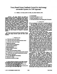
To examine the validity of the circuit implementation and to compare the dynamic behavior of
sc rip
the scaled system in (9) with the equivalent voltages in circuit of Fig. 4, 2D attractors of this system in “xz” phase plane are shown in Fig. 5. Fig. 5.(a), shows the 2D attractor of the state variables of the above circuit, xz phase plane, as it appeared on the screen of digital oscilloscope.
Ma nu
In all measurements we have used Tektronix TDS 210 digital oscilloscope. Similarity between this attractor and that achieved from solving system (9) which is shown in Fig. 5. (b), justifies the
ed
accuracy of circuit implementation. It should be mentioned that, the same resemblances were
Ac
ce
pt
observed between the xy, and yz, attractors of the implemented circuit and those of system (9).
Fig. 5. (a): 2D attractor of the state variable of the designed and implemented circuit, in xz phase plane, (b): attractors in xz phase plane, achieved from solving system (9).
12
Downloaded From: http://computationalnonlinear.asmedigitalcollection.asme.org/pdfaccess.ashx?url=/data/journals/jcnddm/0/ on 07/29/2017 Terms of Use: http://www.asme.or
Journal of Computational and Nonlinear Dynamics. Received February 27, 2017; Accepted manuscript posted August 1, 2017. doi:10.1115/1.4037416 Copyright (c) 2017 by ASME
4.
Synchronization of two chaotic systems with the proposed dynamics
Synchronization of chaotic systems refers to a control design method in which the behaviors of two chaotic systems with different dynamics/initial conditions asymptotically become the same.
ed ite d
In this section, we propose a control design method and real-world circuit implementation for synchronization of two master/slave chaotic systems with the new proposed dynamics (1) and different initial conditions.
py
In order to obtain a practical synchronizing controller, we propose a new non-fragile T-S fuzzy
Co
static output feedback controller by offering some linear matrix inequalities (LMIs). The advantages of the proposed controller are listed as follows: First, T-S fuzzy controllers are used
tN
ot
since they are nonlinear controllers that can be easily designed using LMI techniques. In addition, since in many real-world applications the output of the dynamic system is available for
sc rip
feedback instead of all of its state variables, we propose a new output feedback synchronizing controller. Moreover, to consider the uncertainties of practical analog elements in controller
Ma nu
circuit implementation, we propose a non-fragile output feedback in which some unknown bounded variations are considered in the T-S fuzzy static output feedback controller gains. Furthermore, we consider only one control signal in the dynamics of the slave system to achieve
ed
more practical implementation simplicity.
ce
pt
In the remainder of this section, we first describe the T-S fuzzy model and then derive the
Ac
equivalent T-S fuzzy model of the system (1). Then, we propose a new method for designing a T-S fuzzy non-fragile static output feedback synchronizing controller and present the simulation results. Finally, the designed controller is practically implemented as an analog electronic circuit and successfully used to synchronize to chaotic circuits with the proposed dynamics given in (1).
13
Downloaded From: http://computationalnonlinear.asmedigitalcollection.asme.org/pdfaccess.ashx?url=/data/journals/jcnddm/0/ on 07/29/2017 Terms of Use: http://www.asme.or
Journal of Computational and Nonlinear Dynamics. Received February 27, 2017; Accepted manuscript posted August 1, 2017. doi:10.1115/1.4037416 Copyright (c) 2017 by ASME
4.1. T-S fuzzy model Many nonlinear dynamical systems can be exactly represented via an equivalent T-S fuzzy model by employing the sector nonlinearity approach [30]. In fact, by defining a compact set for
ed ite d
the state variables of the nonlinear system, the original nonlinear model is represented by nonlinear aggregating some local linear time-invariant models. A T-S fuzzy model consists of the following rules [30]:
py
Model Rule i:
,r
(10)
ot
, i 1, 2,
tN
x (t ) Ax i (t ) Bi u(t ) THEN y (t ) C i x (t )
Co
IF 1 is M i 1 and ... and p is M ip ,
sc rip
where [ 1 2 p ] is the vector of scalar functions which depend to state variables, r is the number of fuzzy rules, Mij determines the membership function of the i-th rule and j-th premise variable, x (t ) n , u (t ) m , and y (t ) p are the state, input, and output vectors,
Ma nu
respectively and Ai nn , B i n1 , Ci pn represent the system matrices of the local fuzzy system. The final representation form of a T-S fuzzy system is deduced as: r
x (t ) hi ( (t )) A i x (t )+B i u (t )
ed
(11)
pt
i 1
r
y (t ) hi ( (t ))C i x (t ),
(12)
ce
i 1
Ac
The nonlinear aggregation scalar functions hi ( (t )) satisfy the following properties: 0 hi ( ) 1,
r
h ( ) 1. i 1
i
(13)
14
Downloaded From: http://computationalnonlinear.asmedigitalcollection.asme.org/pdfaccess.ashx?url=/data/journals/jcnddm/0/ on 07/29/2017 Terms of Use: http://www.asme.or
Journal of Computational and Nonlinear Dynamics. Received February 27, 2017; Accepted manuscript posted August 1, 2017. doi:10.1115/1.4037416 Copyright (c) 2017 by ASME
In this paper, we use the following notation for the sake of brevity: r
A hi ( (t ))A i .
(14)
i 1
ed ite d
4.2. T-S fuzzy model of the proposed chaotic system
In this section, we use the notation x [x y z ]T to represent the state vector of the chaotic
py
system (1). As we mentioned earlier, the equivalent T-S fuzzy model for the chaotic system (1)
Co
can be easily obtained via the sector nonlinearity approach. We suppose that d1 x d1 and
d 2 y d 2 . Then, the following four-rule T-S model can be derived to represent the original
ot
nonlinear chaotic system (1) with the model parameters are set as; (a, b, c, d, e, f, g, h, m, n) =
tN
(10, 10, 1.5, 3, 70, 1, 0.5, 0.5, 0.5, 5):
i 1
Ma nu
where (t ) [x (t ) y (t )]T and:
sc rip
4
x (t ) hi ( )A i x (t ),
(16)
x(t ) d1 y (t ) d 2 x(t ) d1 d 2 y (t ) , h2 ( (t )) , 2d1 2d 2 2d1 2d 2
Ac
h1 ( (t ))
ce
pt
ed
10 10 1.5 3d 2 10 10 1.5 3d 2 A1 35 1 0 35 1 0 , A2 , 5d 2 2.5d1 10d 2 5 5 5d 2 2.5d1 10d 2 10 10 1.5 3d 2 10 10 1.5 3d 2 A3 35 1 0 35 1 0 , A4 , 5d 2 2.5d1 10d 2 5d 2 2.5d1 10d 2 5 5 with:
(15)
d x(t ) y (t ) d 2 d x(t ) d 2 y (t ) h3 ( (t )) 1 , h4 ( (t )) 1 . 2d1 2d 2 2d1 2d 2
(17)
15
Downloaded From: http://computationalnonlinear.asmedigitalcollection.asme.org/pdfaccess.ashx?url=/data/journals/jcnddm/0/ on 07/29/2017 Terms of Use: http://www.asme.or
Journal of Computational and Nonlinear Dynamics. Received February 27, 2017; Accepted manuscript posted August 1, 2017. doi:10.1115/1.4037416 Copyright (c) 2017 by ASME
4.3. Non-fragile static output feedback T-S fuzzy controller Consider the following master and slave chaotic systems with the dynamics (1) which are represented by their T-S fuzzy corresponding models in (15) as:
ed ite d
x m (t ) A m x m (t ), y m (t ) Cx m (t ), x s (t ) A s x s (t ) Bu (t ),
(19)
py
y s (t ) Cx s (t ),
(18)
Co
where:
(20)
tN
ot
1 1 0 0 B 0 , C . 0 1 0 0
sc rip
Notice that by using (20), we use only one control signal to synchronize the abovementioned chaotic systems. In order to determine the controller structure, we propose a non-fragile static output feedback controller as:
r
Ma nu
u (t ) (K s K s )( y s (t ) y m (t )) hi ( s )(K i K i )( y s (t ) y m (t )),
(21)
i 1
ed
where K i are controller gains and notation (14) is used. Moreover, K i 's are unknown bounded matrices which are partitioned as:
K i (t ) E (t )Fi ; i 1,...., r
ce
pt
(22)
Ac
with (t ) is a bounded matrix with (t )T (t ) I and E , Fi ( i 1,...., r ) are known matrices with appropriate dimensions. It should be noted that the terms K i are gain variations caused by uncertainty in values of practical electronic components. Now define e (t ) x s (t ) x m (t ) as the synchronization error. The derivative of e (t ) is given by:
16
Downloaded From: http://computationalnonlinear.asmedigitalcollection.asme.org/pdfaccess.ashx?url=/data/journals/jcnddm/0/ on 07/29/2017 Terms of Use: http://www.asme.or
Journal of Computational and Nonlinear Dynamics. Received February 27, 2017; Accepted manuscript posted August 1, 2017. doi:10.1115/1.4037416 Copyright (c) 2017 by ASME
e (t ) A s x s (t ) B (K s K s )C (x s (t ) x m (t )) A m x m (t ),
(23)
Equation (23) can be rewritten as: e (t ) A s x s (t ) B (K s K s )C (x s (t ) x m (t )) A m x m (t ) A s x m (t )
ed ite d
Acls e (t ) w (t ),
where: Acls (A s B (K s K s )C ),
py
w (t ) (A s A m )x m (t ).
(24)
(25) (26)
Co
Notice that the signal w (t ) is considered as a disturbance signal and it is clear that this signal is
ot
bounded.
w (t )
L2
,
sc rip
Qe (t ) sup
tN
In this paper, we design the controller gains such that the following performance index holds:
L2
(27)
Ma nu
where is a pre-chosen attenuation level and Q is a known weighting symmetric positive definite matrix. The methodology for designing a synchronizing controller satisfying (27) will be offered in the next subsection. The following lemmas will be used in the proof of the main result
ed
of the next subsection:
ce
holds:
pt
Lemma 1 [30]: for matrices X and Y with appropriate dimensions, the following inequality
X TY Y T X X T X 1Y TY ,
Ac
(28)
where is a positive scalar.
17
Downloaded From: http://computationalnonlinear.asmedigitalcollection.asme.org/pdfaccess.ashx?url=/data/journals/jcnddm/0/ on 07/29/2017 Terms of Use: http://www.asme.or
Journal of Computational and Nonlinear Dynamics. Received February 27, 2017; Accepted manuscript posted August 1, 2017. doi:10.1115/1.4037416 Copyright (c) 2017 by ASME
Lemma 2 [31]: Suppose that matrix H m n with rank (H ) m is given. Assuming that X n n is a symmetric matrix, then the equality MX XM holds for a matrix X m m if
and only if X is partitioned by:
ed ite d
0 T X X V 11 V , 0 X 22
py
where M is decomposed as M U [ S 0]V T .
(29)
Co
4.4. A new method for the non-fragile T-S fuzzy controller synthesis In this subsection, we propose a new method for designing the non-fragile static output feedback
ot
controller in (21) to synchronize the master-slave chaotic systems in (18)-(19). It is noted that the
tN
proposed method in this section is not limited to the proposed chaotic system in this paper and it
sc rip
can be applied to master-slave chaotic synchronization of other chaotic systems whose TS representations are similar to (18)-(19).
Ma nu
Theorem 1. Suppose that the output matrix C has the SVD form C U [S 0]V T . The closedloop system (24) satisfies the performance index (27) if there exist symmetric positive definite matrices X 11 and X 22 , matrices M i (i 1,..., r ) , scalars and , such that the following LMIs
ed
hold:
Ac
ce
pt
T T A i X BM i (A i X BM i ) BEE B I 1 Q 2X Fi CX
1
I
XQ 2
I
0
0
I
0
0
X C T FiT 0 0, 0 I
(30)
where:
18
Downloaded From: http://computationalnonlinear.asmedigitalcollection.asme.org/pdfaccess.ashx?url=/data/journals/jcnddm/0/ on 07/29/2017 Terms of Use: http://www.asme.or
Journal of Computational and Nonlinear Dynamics. Received February 27, 2017; Accepted manuscript posted August 1, 2017. doi:10.1115/1.4037416 Copyright (c) 2017 by ASME
X X V 11 0
0 T V . X 22
(31)
Moreover, the attenuation level in (27) is derived by and the controller gains K i can
ed ite d
be obtained by: K j M j X 21 ,
Proof: Consider the following Lyapunov function candidate:
Co
V (e (t )) e T (t )Pe (t ),
py
with X 2 USX 11S 1U 1 .
(33)
ot
where P P T 0 is the Lyapunov matrix.
(32)
tN
The derivative of V (e (t )) along the closed-loop error trajectories in (24) is given by:
sc rip
V (e (t )) e T (t )(PAcls (Acls )T e (t ) e T (t )Pw (t ) w T (t )Pe (t ).
(34)
It is well-known that (34) holds if the following inequality is satisfied:
Ma nu
V (e (t )) e T (t )Qe (t ) 2w T (t )w (t ) 0.
(35)
By substituting (34) in (35), one has: e (t ) (Acls )T P PAcls Q P w (t )
P e (t ) 0, 2 I w (t )
(36)
ed
T
pt
or equivalently:
P 0. 2 I
ce
(Acls )T P PAcls Q P
Ac
(37)
Pre-and post-multiplying (37) by diag (X , I ) with X P 1 , and then applying Schur complement on the resulting inequality yields:
19
Downloaded From: http://computationalnonlinear.asmedigitalcollection.asme.org/pdfaccess.ashx?url=/data/journals/jcnddm/0/ on 07/29/2017 Terms of Use: http://www.asme.or
Journal of Computational and Nonlinear Dynamics. Received February 27, 2017; Accepted manuscript posted August 1, 2017. doi:10.1115/1.4037416 Copyright (c) 2017 by ASME
T
I 2 I 0
1 XQ 2 0 0. I
(38)
Note that the term Acls X can be written by: Acl s X (A s B (K s K s )C )X A s X B (K s K s )CX .
ed ite d
s s T Acl X X Acl I 1 Q 2X
(39)
py
Now suppose that CX XC , where X is a new unknown matrix. Then, by using (22), equation
Co
(39) can be written by:
tN
By defining M s K s X , (40) is rewritten as:
Ma nu
sc rip
T T A s X B s M s C (A s X B s M s C ) BE s (t )Fs CX (BE s (t )Fs CX ) I 1 2 Q X
Using Lemma 1, (41) is equivalent to:
I
XQ
2 I
0
0
I
0
0
pt
ed
T T A s X B s M s () BE s E s B I 1 XQ 2 Fs CX
(40)
ot
Acl s X As X BK s XC BEs (t ) Fs CX .
1 2
X C T FTs 0 0, 0 I
I 2 I 0
1 XQ 2 0 0. I
(41)
(42)
ce
where is an unknown positive scalar.
Ac
Using the notation in (14) to expand (42), it is clear that (30) is a sufficient condition for satisfying (42). Notice that using Lemma 2, the condition CX XC holds if X is partitioned as (31). Thus, to recover the controller gain from the solutions of the LMIs (30) which are
M i (i 1,..., r ), X 11 and X 22 , one has: 20
Downloaded From: http://computationalnonlinear.asmedigitalcollection.asme.org/pdfaccess.ashx?url=/data/journals/jcnddm/0/ on 07/29/2017 Terms of Use: http://www.asme.or
Journal of Computational and Nonlinear Dynamics. Received February 27, 2017; Accepted manuscript posted August 1, 2017. doi:10.1115/1.4037416 Copyright (c) 2017 by ASME
K j M jX
1
.
(43)
To find X , one can use the conditions CX XC associated by the special form of X in (31): 0 T V XU [ S 0]V T . X 22
(44)
ed ite d
X U [ S 0] V TV 11 0
Using the properties of the SVD, one has V TV I . Then, (44) can be rewritten by:
py
USX 11 XUS ,
or equivalently:
Co
X USX 11 (US )1 USX 11S 1U 1.
(46)
ot
This completes the proof. ■
(45)
tN
Remark 1. In Theorem 1, we proposed a new method to design a non-fragile static output
sc rip
feedback TS fuzzy controller for synchronization of master-slave chaotic systems. In fact, we define a new performance criterion for attenuating the effect of a disturbance signal on the
Ma nu
synchronization error. Then, using the aim of the equality constraint given in Lemma 2, we converted the design conditions into some LMIs which can be easily solved via existing solvers. To the best of our knowledge, this problem had not been yet considered in the literature.
ed
Moreover, it should be noted that in contrast with the method of [32] which study the
pt
stabilization problem, we proposed the problem of synchronization of chaotic systems. It is well-
ce
known that the synchronizing controller design can be regarded as a special case of the tracking
Ac
controller design which is more complex than the stabilizing controller design in general. 4.5. Numerical simulations In this section, we propose numerical simulations to show the effectiveness of the proposed linear controller. Suppose that d1 d 2 3 , Q I and the matrices in (22) are defined as:
21
Downloaded From: http://computationalnonlinear.asmedigitalcollection.asme.org/pdfaccess.ashx?url=/data/journals/jcnddm/0/ on 07/29/2017 Terms of Use: http://www.asme.or
Journal of Computational and Nonlinear Dynamics. Received February 27, 2017; Accepted manuscript posted August 1, 2017. doi:10.1115/1.4037416 Copyright (c) 2017 by ASME
0.1 E , F1 F2 F3 F4 0.1. 0.5 We solve the LMIs of Theorem 1 using SeDuMi [33] as solver in MATLAB®, which leads to the
ed ite d
following LMI solutions:
63.1216 -2.3379 X 11 , -2.3379 3.1580 M 1 10 -2.2512 - 0.0867 , M 2 10 -9.3230 - 3.2540 , 3
Consequently, the controller gains are obtained as:
Co
M 3 103 -5.2220 - 2.7322 , M 4 10 4 -4.6712 -0.0146 .
(47)
py
4
k 12 ] 377.1475 533.7601 , K 2 [k 21
k 22 ] 118.0094 952.5290 ,
K 3 [k 31
k 32 ] 762.6544 610.9333 , K 4 [k 41
k 42 ] 191.1213 1171.9011 .
r
u (t ) hi ( s )K i ( y s (t ) y m (t )). i 1
sc rip
Finally, the control signal is proposed as:
tN
ot
K 1 [k 11
(48)
Ma nu
It should be noted that although the calculated gain values are relatively large, when applied to the practical system these values should be normalized which reduces the ki1 gains by a factor
ed
five and ki2 gains (i = 1,…,4) by a factor of ten and therefore facilitate the practical
pt
implementation.
ce
In the simulations, we consider the initial conditions for master and slave systems (18) and (19)
Ac
as [0.1,0.1,-0.1]T and [0.2,0.2,-0.5]T, respectively. The simulation results for the closed-loop synchronization error system are depicted in Figs. 6 and the control signal applied to the slave system is depicted in Fig. 7. According to these figures, one can observe that the proposed controller asymptotically stabilizes the error system and the synchronization errors successfully converge to zero. 22
Downloaded From: http://computationalnonlinear.asmedigitalcollection.asme.org/pdfaccess.ashx?url=/data/journals/jcnddm/0/ on 07/29/2017 Terms of Use: http://www.asme.or
ed ite d
Journal of Computational and Nonlinear Dynamics. Received February 27, 2017; Accepted manuscript posted August 1, 2017. doi:10.1115/1.4037416 Copyright (c) 2017 by ASME
ot
Co
py
Fig. 6. Synchronization errors of x, y, and z component of the two chaotic systems.
tN
Fig. 7. Control signal u(t) applied to slave system.
4.6. Controller circuit design and implementation results
sc rip
Uncertainty is inevitable in practical systems. It can be because of the finite tolerance of value of the individual components in an analog system (e.g. finite precision in value of circuit elements
Ma nu
in an electronic circuit), or because of finite precision of numbers in a digital system. The former case happens in problem of synchronization of two chaotic electronic circuits. As mentioned earlier here to reduce the sensitivity of the controller to inherent uncertainty of the system a non-
ed
fragile controller has been designed. Circuit implementation of the designed controller can be
pt
done in a straightforward manner. According to (48), the controller circuit should only measure x
ce
and y state variables from two chaotic circuits (each of which implementing system in (9)), and
Ac
then one can construct the control signal u(t). From equation (48) can be rewritten as: u (t ) h1 ( (t ))k11e1 (t ) k12 e2 (t ) h2 ( (t ))k 21e1 (t ) k 22 e2 (t ) h3 ( (t ))k31e1 (t ) k32 e2 (t ) h4 ( (t ))k 41e1 (t ) k 42 e2 (t )
(49)
where
23
Downloaded From: http://computationalnonlinear.asmedigitalcollection.asme.org/pdfaccess.ashx?url=/data/journals/jcnddm/0/ on 07/29/2017 Terms of Use: http://www.asme.or
Journal of Computational and Nonlinear Dynamics. Received February 27, 2017; Accepted manuscript posted August 1, 2017. doi:10.1115/1.4037416 Copyright (c) 2017 by ASME
e1 (t ) X m (t ) X s (t ) e2 (t ) Ym (t ) Ys (t ) and Xm, Ym and Xs, Ys are x and y state variables of the master and slave circuits, respectively.
ed ite d
Fig. 8 shows the block diagram of the non-fragile controller in (49). Four square blocks in this figure produce the four different terms in equation (49) and the operational amplifier adds these terms to from the control signal u(t). Each block in Fig. 8(a) which is composed of operational
py
amplifiers, analog multipliers and resistors, gets Xm, Ym and Xs, Ys and a constant voltage value V0
Co
and produces one of the terms given in (49). Here for the sake of simplicity only the internal circuitry of the first block (which produces the term: h1 ( (t ))k11e1 (t ) k12 e2 (t )) is shown in the
ot
Fig. 8(b). The other three terms are also implemented in the same way with slight differences in
tN
sign and value of the gain of the operational amplifiers.
sc rip
Resulting control signal u(t) will be then applied as an additional term to the X state of one the circuits, noted as the slave circuit. The other circuit is noted as the master circuit. Master and
Ma nu
slave circuits are technically the same, only a few components should be added to the slave circuit to provide the facility of applying control signal to this circuit (see Fig. 9). In the controller circuit, state variables of the master and slave circuits are sensed at the Xm, Ym and Xs,
ed
Ys ports, respectively.
pt
As mentioned above, a few circuit elements should be added to the circuit in Fig. 4 to implement
ce
the slave system. The slave circuit is shown in Fig. 9, in which the additional components for
Ac
applying u(t) are marked as the shaded region.
24
Downloaded From: http://computationalnonlinear.asmedigitalcollection.asme.org/pdfaccess.ashx?url=/data/journals/jcnddm/0/ on 07/29/2017 Terms of Use: http://www.asme.or
ed ite d
Journal of Computational and Nonlinear Dynamics. Received February 27, 2017; Accepted manuscript posted August 1, 2017. doi:10.1115/1.4037416 Copyright (c) 2017 by ASME
Co
py
Fig. 8. (a): Block diagram of the designed controller in (48). (b): Internal circuitry of block B1; TL084 low cost quad op-amps, AD633 analog multiplier, R = 1kΩ, R1 = 1.5kΩ, R2 = R3 = 6.8kΩ, R4 = R5 = 1kΩ, R6 = R7 = 7.5kΩ, R8 = 1.3kΩ, R9 = R10 = 7.5kΩ, R11 = R12 = 1.6kΩ, R13 = R14 = 6.8kΩ, R15 = R16 = 1kΩ, R18 = R19 = 10R17 = 10kΩ, R21 = 19R20 = 19kΩ, R23 = R24 = 10R22 = 10kΩ, R26 = 29R25 = 29kΩ and R27 = R28 = R29 = 1kΩ. In all circuits we have used supply voltages V+ = +9V and V- = -9V.
To estimate the level of synchronization between the master and slave systems before applying
ot
any control signals to the slave system, we have measured state variables of these systems when
tN
u(t) port in Fig. 9 is connected to ground of the circuit. Notice that in this case the master and
sc rip
slave circuits are exactly the same. The 2D xy plots of the “x” state variables of these two systems are shown in Fig. 10. In this figure, the x state variable of the master system is illustrated as a function of its corresponding variable in the slave system by capturing two oscilloscope
Ma nu
channels in xy mode. It should be mentioned that, although it is not presented here, same results
Ac
ce
pt
ed
were observed for the y and z states of the master and slave systems.
Fig. 9. Circuit diagram for the slave system. AD633: Analog multiplier, TL082 and TL084 low cost dual and quad op-amps, respectively. R1 = 100kΩ, R2 = 5kΩ, R3 = 7.5kΩ, R4 = 25kΩ, R5 = 10kΩ, R6 = 150kΩ, R7 = 10kΩ (potentiometer), R8=1kΩ, R9 = 1.2kΩ, R10 = 1.6kΩ, R11 = 56kΩ, R12 = 680Ω, R13 = 9kΩ, R14 = 12kΩ, R15 = 40kΩ,
25
Downloaded From: http://computationalnonlinear.asmedigitalcollection.asme.org/pdfaccess.ashx?url=/data/journals/jcnddm/0/ on 07/29/2017 Terms of Use: http://www.asme.or
Journal of Computational and Nonlinear Dynamics. Received February 27, 2017; Accepted manuscript posted August 1, 2017. doi:10.1115/1.4037416 Copyright (c) 2017 by ASME
ed ite d
R16 = 20kΩ, R17 = 250kΩ, R18 = 1MΩ, R19 = 3kΩ, R20 = 1.5kΩ, and C = 200nF. In all circuits we have used supply voltages V+ = +9V and V- = -9V.
Co
py
Fig. 10. Before applying the control signal to the slave system. (a): Xm(t) as a function of Xs(t), (b): error between x components of the master and slave systems; e1(t) = Xm(t) – Xs(t).
As it can be seen in Fig. 10 (a), the x state variables of two systems (i. e. Xm and Xs) are fully out
ot
of synchronization and therefore their xy plots occupy square regions with each of their sides
tN
equal to oscillation range these components. After measuring state variables of the master and
sc rip
slave systems, we also calculated error between corresponding components of two systems; e1(t) = Xm(t) – Xs(t). The error for x variables are shown in Fig. 10 (b). Large value of error in these
applying the control signal.
Ma nu
figures once again clears the lack of synchronization between master and slave systems before
To test the ability of the designed controller in synchronizing two chaotic circuits, the control
ed
signal produced by circuit in Fig. 8 was applied to the slave system through u(t) port in Fig. 9.
pt
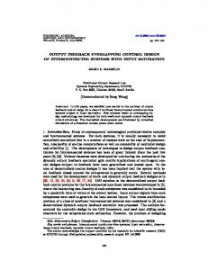
Results of measurements of the x state variables of the master and slave systems are shown in
ce
Fig. 11. Fig. 11 (a) shows the xy plots of x variables of the master and slave systems. As it can be
Ac
seen, the xy plot of the x state variable of two systems form a line with unity slope. This means that the state variables of the master system are synchronized with those of the slave system. To further verify the synchronization of two systems, error between x state variables of two systems e1(t), is also measured and illustrated in Fig. 11 (b). Negligible value of error in this figure once
26
Downloaded From: http://computationalnonlinear.asmedigitalcollection.asme.org/pdfaccess.ashx?url=/data/journals/jcnddm/0/ on 07/29/2017 Terms of Use: http://www.asme.or
Journal of Computational and Nonlinear Dynamics. Received February 27, 2017; Accepted manuscript posted August 1, 2017. doi:10.1115/1.4037416 Copyright (c) 2017 by ASME
again emphasizes the success of the designed controller in synchronizing the master and slave
py
ed ite d
systems.
Co
Fig. 11. After applying control signal to the slave system. (a): Xm(t) as a function of Xs(t), (b): error between x components of the master and slave systems; e1(t) = Xm(t) – Xs(t).
ot
As another illustration of effective synchronization between the master and slave systems,
tN
transient behavior of the error between their corresponding state variables is measured. In this
sc rip
experiment, u(t) port of the slave system is switched from ground to control signal while errors e1(t), e2(t) and e3(t) are captured by digital oscilloscope and sent to computer. The transient error
Ma nu
between x, y and z variables of the master and slave system are presented in Fig. 12 (a), (b) and (c), respectively. These figures verify our previous statements about synchronization of the
Ac
ce
pt
ed
master and slave systems.
Fig. 12. Measured synchronization errors of x, y, and z component of the two chaotic systems dots: data captured from oscilloscope, red curve: curve fitted by data interpolation.
27
Downloaded From: http://computationalnonlinear.asmedigitalcollection.asme.org/pdfaccess.ashx?url=/data/journals/jcnddm/0/ on 07/29/2017 Terms of Use: http://www.asme.or
Journal of Computational and Nonlinear Dynamics. Received February 27, 2017; Accepted manuscript posted August 1, 2017. doi:10.1115/1.4037416 Copyright (c) 2017 by ASME
5. Conclusions The main purposes of this paper are the analysis of the new three dimensional chaotic systems and also its synchronization using a novel fuzzy approach. For the evaluation of chaotic
ed ite d
behavior, many mathematical tools such Lyapunov exponents and bifurcation diagram is used. On the other hand, a novel TS fuzzy method is employed to synchronize the master and slave systems. For demonstrating our claims, both purposes are implemented using analog circuits to
py
analyze the applicability in practice. Numerical and experimental results show the effectiveness
Co
of proposed framework.
ot
References
tN
[1] Ivancevic, V. G., Ivancevic, T. T. Complex nonlinearity: chaos, phase transitions, topology change, and path integrals. Springer Science & Business Media. Berlin: Springer; 2008.
planetary change, 41, 95-109(2004)
sc rip
[2] Rial, J., A. Abrupt climate change: chaos and order at orbital and millennial scales. Global and
[3] Chen, D., Liu, W. Chaotic behavior and its control in a fractional-order energy demand–supply system. ASME. J. Comput. Nonlinear Dynam., 11(6), 061010-061010-7 (2016).
Ma nu
[4] Zhou, L., Chen, F., Chen, Y. Bifurcations and chaotic motions of a class of mechanical system with parametric excitations. ASME. J. Comput. Nonlinear Dynam., 10(5), 054502-054502-8 (2015). [5] Carlen, E., Chatelin, R., Degond, P., Wennberg, B. Kinetic hirerachy and propagation of chaos in biological swarm models. Physica D: Nonlinear Phenomena, 260, 90-111(2013)
ed
[6] Towfighian, S., S., Heppler, G., R., Abdel-Rahman, E., M. Analysis of a chaotic electrostatic micro-
pt
oscillator. ASME. J. Comput. Nonlinear Dynam., 6(1), 011001-011001-10 (2010). [7] Callan, K. L., Illing, L., Gao, Z., Gauthier, D. J.; Schöll, E. Broadband chaos generated by an
ce
optoelectronic oscillator. Phys. Rev. Lett., 104, 113901-1:4(2010).
Ac
[8] Liu, P., Song, H., Li X. Observe-based projective synchronization of chaotic complex modified Van Der Pol-Duffing oscillator with application to secure communication. ASME. J. Comput. Nonlinear Dynam., 10(5), 051015-051015-7 (2015). [9] Xu Y., Wang H., Li Y., Pei B. Image encryption based on synchronization of fractional chaotic systems. Commun Nonlinear Sci Numer Simul, 19, 3735-3744(2014). [10] Lorenz, E. N. Deterministic nonperiodic flow. J. Atmos. Sci., 20, 130-141(1963).
28
Downloaded From: http://computationalnonlinear.asmedigitalcollection.asme.org/pdfaccess.ashx?url=/data/journals/jcnddm/0/ on 07/29/2017 Terms of Use: http://www.asme.or
Journal of Computational and Nonlinear Dynamics. Received February 27, 2017; Accepted manuscript posted August 1, 2017. doi:10.1115/1.4037416 Copyright (c) 2017 by ASME
[11] Liu, Y., Li, L., Feng, Y. Finite-time synchronization for high-dimensional chaotic systems and its application to secure communication. J. Comput. Nonlinear Dynam., 11(1), 051028 (2016). [12] Lü, J., Chen, G. A new chaotic attractor coined. International Journal of Bifurcation and chaos, 12, 659-661(2002). [13] Arefi, M. Adaptive robust stabilization of Rossler system with time-varying mismatched parameters
ed ite d
via scalar input. ASME. J. Comput. Nonlinear Dynam., 11(4), 041024-041024-6 (2016). [14] Sprott, J. C. A new class of chaotic circuit. Physics Letters A, 266, 19-23(2000).
[15] Rezaei., D, Tavazoei, M. Analysis of Oscillations in Relay Feedback Systems with Fractional-Order Integrating Plants. ASME. J. Comput. Nonlinear Dynam., (2017). doi:10.1115/1.4037103.
py
[16] Cang, S., Qi, G.; Chen, Z. A four-wing hyper-chaotic attractor and transient chaos generated from a
Co
new 4-D quadratic autonomous system. Nonlinear Dynamics, 59, 515-527(2010).
[17] Zarei, A. Complex dynamics in a 5-D hyper-chaotic attractor with four-wing, one equilibrium and
ot
multiple chaotic attractors. Circuits Sys. Signal Process. 81, 585-605(2015).
tN
[18] Singh, A. K., Yadav, V. K. Dual combination synchronization of the fractional order complex systems. J. Comput. Nonlinear Dynam., 12(1), 011017 (2016).
sc rip
[19] Khamsuwan, P., Kuntanapreeda, S. A linear matrix inequality approach to output feedback control of fractional-order unified chaotic systems with one control input. J. Comput. Nonlinear Dynam., 11(5), 051021 (2016).
Ma nu
[20] Klostermann, H., Rohde, A., Piel, A. Van der Pol behavior of virtual anode oscillations in the shealth around a grid in a double plasma device. Phys. Plasmas, 4, 254-260(1997). [21] Tang, Y., Mees, A.; Chua, L. O. Synchronization and chaos. IEEE Transactions on Circuits & Systems, 30, 620-626(1983).
ed
[22] Feng, C., Cai, L., Kang, Q., Wang, S., Zhang, H. Novel hyperchaotic system and its circuit implementation. ASME. J. Comput. Nonlinear Dynam., 10(6), 061012-061012-7 (2015).
pt
[23] Rafiq Dar, M., Ali Kant N., Ahmad Khanday, F. Electronic implementation of fractional-order
ce
Newton–Leipnik chaotic system with application to communication. ASME. J. Comput. Nonlinear
Ac
Dynam., 12(5), 054502-054502-5 (2017). [24] J. Kaplan and J. A. Yorke [Springer Lecture Notes in Mathematics730, 204 (1979)] [25] Asemani M.H., Yazdanpanah, M. J., Majd, V. J., Golabi, A., H∞ control of TS fuzzy singularly perturbed systems using multiple Lyapunov functions. Circuits, Systems, and Signal Processing, 32, 2243-2266(2013). [26] Li, H., Wang, J., Wu, L., Lam, H. K., Gao, Y. Optimal guaranteed cost sliding mode control of interval type-2 fuzzy time-delay systems, IEEE Transactions on Fuzzy Systems, vol. PP(99), 1-1
29
Downloaded From: http://computationalnonlinear.asmedigitalcollection.asme.org/pdfaccess.ashx?url=/data/journals/jcnddm/0/ on 07/29/2017 Terms of Use: http://www.asme.or
Journal of Computational and Nonlinear Dynamics. Received February 27, 2017; Accepted manuscript posted August 1, 2017. doi:10.1115/1.4037416 Copyright (c) 2017 by ASME
(2017). doi: 10.1109/TFUZZ.2017.2648855 [27] Razavi-Panah, J., Majd, V. J., A robust multi-objective DPDC for uncertain T–S fuzzy systems.
Fuzzy sets and systems, 159 (20), 2749-2762 (2008). [28] Li, H., Wang J., Du H., Karimi H. R. Adaptive Sliding Mode Control for Takagi-Sugeno Fuzzy Systems and Its Applications. IEEE Transactions on Fuzzy Systems, PP(99), 1-1 (2017).
ed ite d
[29] Buscarino A., Fortuna L., Frasca M., Sciuto G. A Concise Guide to Chaotic Electronic Circuits. Berlin: Springer; 2014.
[30] Lan, Y. H., Zhou, Y. Non-fragile observer-based robust control for a class of fractional-order nonlinear systems, Systems & Control Letters, 62, 1143-1150(2013).
py
[31] Huang, S. J., Yang, G. H. Non-fragile H∞ dynamic output feedback control for uncertain Takagi–
Co
Sugeno fuzzy systems with time-varying delay. International Journal of Systems Science, 47, 29542964(2016).
[32] Guan, W., Liu, F. Non-fragile fuzzy dissipative static output feedback control for Markovian jump
ot
systems subject to actuator saturation, Neurocomputing, 193, 123-132(2016).
tN
[33] Sturm J. F. Using SeDuMi 1.02, a Matlab toolbox for optimization over symmetric cones. Optim.
Ac
ce
pt
ed
Ma nu
sc rip
Methods. Softw., 11, 625–653(1999).
30
Downloaded From: http://computationalnonlinear.asmedigitalcollection.asme.org/pdfaccess.ashx?url=/data/journals/jcnddm/0/ on 07/29/2017 Terms of Use: http://www.asme.or