formed underwater, through special rubber gaskets. Despite the necessity of specialist equipment, these tunnels have certain ad- vantages compared to bored ...
Nonlinear Response of Deep Immersed Tunnel to Strong Seismic Shaking Ioannis Anastasopoulos1; Nikos Gerolymos2; Vasileios Drosos3; Rallis Kourkoulis4; Takis Georgarakos5; and George Gazetas, M.ASCE6 Abstract: Critical for the seismic safety of immersed tunnels is the magnitude of deformations developing in the segment joints, as a result of the combined longitudinal and lateral vibrations. Analysis and design against such vibrations is the main focus of this paper, with reference to a proposed 70 m-deep immersed tunnel in a highly seismic region, in Greece. The multisegment tunnel is modeled as a beam connected to the ground through properly calibrated interaction springs, dashpots, and sliders. Actual records of significant directivityaffected ground motions, downscaled to 0.24 g peak acceleration, form the basis of the basement excitation. Free-field acceleration time histories are computed from these records through one-dimensional wave propagation equivalent-linear and nonlinear analyses of parametrically different soil profiles along the tunnel; they are then applied as excitation at the support of the springs, with a suitable time lag to conservatively approximate wave passage effects. The joints between the tunnel segments are modeled realistically with special nonlinear hyperelastic elements, while their longitudinal prestressing due to the great 共7 bar兲 water pressure is also considered. Nonlinear dynamic transient analysis of the tunnel is performed without ignoring the inertia of the thick-walled tunnel, and the influence of segment length and joint properties is investigated parametrically. It is shown that despite ground excitation with acceleration levels exceeding 0.50 g and velocity of about 80 cm/ s at the base of the tunnel, net tension and excessive compression between the segments can be avoided with a suitable design of joint gaskets and a selection of relatively small segment lengths. Although this research was prompted by the needs of a specific project, the dynamic analysis methods, the proposed design concepts, and many of the conclusions of the study are sufficiently general and may apply in other immersed tunneling projects. DOI: 10.1061/共ASCE兲1090-0241共2007兲133:9共1067兲 CE Database subject headings: Tunnels; Earthquakes; Dynamic analysis; Soil-structure interaction; Vibration; Nonlinear response; Seismic effects.
Introduction In this century, more than 100 immersed tunnels have been constructed in the world for road or rail crossings 共Ingerslev 1998兲. Typically consisting of prefabricated floatable segments 100– 150 m in length, they are usually constructed in a dry-dock, made watertight with the use of special bulkheads, floated over a pre-excavated trench, and lowered with the help of special sinking rigs. The connection of two consecutive segments is performed underwater, through special rubber gaskets. Despite the necessity of specialist equipment, these tunnels have certain ad1
Postdoctoral Researcher, National Technical Univ., Athens, Greece. Lecturer, National Technical Univ., Athens, Greece. 3 Graduate Research Assistant, National Technical Univ., Athens, Greece. 4 Graduate Research Assistant, National Technical Univ., Athens, Greece. 5 Graduate Research Assistant, National Technical Univ., Athens, Greece. 6 Professor, National Technical Univ., Athens, Greece. Note. Discussion open until February 1, 2008. Separate discussions must be submitted for individual papers. To extend the closing date by one month, a written request must be filed with the ASCE Managing Editor. The manuscript for this paper was submitted for review and possible publication on June 7, 2005; approved on March 5, 2007. This paper is part of the Journal of Geotechnical and Geoenvironmental Engineering, Vol. 133, No. 9, September 1, 2007. ©ASCE, ISSN 1090-0241/2007/ 9-1067–1090/$25.00. 2
vantages compared to bored tunnels: They can be placed at the minimum possible depth, thus, minimizing both the imposed water-pressures and the total tunnel length; boring through relatively loose permeable soils at the sea bottom can be avoided; their construction is mostly performed ashore, ensuring high quality. The vast majority of already built immersed tunnels are located in regions of low seismicity 共State-of-the-Art Report 1997兲. In 1997, out of 108 existing or under construction immersed tunnels, 42 were situated in the very-low-seismicity North-Western Europe, 26 in the United States of America, and 20 in Japan. In seismically active regions, earthquake loading can be critical and should be carefully taken into account 共Ingerslev and Kiyomiya 1997; JSCE 1988兲. The main objective of the present paper is to investigate the seismic response of a very-deep immersed tunnel, under the simultaneous action of longitudinal, transversal, and vertical seismic excitation. Emphasis is given to the consequences of longitudinal oscillations. This is the critical mode of earthquakeinduced vibration, and one of the most severe loading situations for an immersed tunnel, since it may lead to decompression of the joint gaskets, jeopardizing the watertightness 共and, hence, the safety兲 of the tunnel. Bending and shearing deformations due to lateral and vertical oscillations are not as serious a problem, since large “shear keys” can undertake the induced loads. A complete seismic safety evaluation of the immersed tunnel is beyond the scope of this paper. For a proper assessment of the consequences of longitudinal and lateral vibrations, a certain degree of sophistication in our
JOURNAL OF GEOTECHNICAL AND GEOENVIRONMENTAL ENGINEERING © ASCE / SEPTEMBER 2007 / 1067
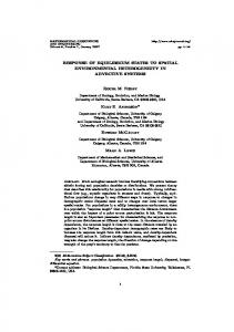
Fig. 1. 共a兲 Seismicity map of Greece 共EAK 2000兲; 共b兲 major faults affecting the area of study 关based on Tselentis et al. 共2004兲, Armijo et al. 共1996兲, and Bernard et al. 共1997兲兴; and 共c兲 plan view of the proposed railway link
analysis is necessary. Thus, nonlinear dynamic transient analysis of the multisegment tunnel is performed in which: 共1兲 the behavior of the joints between segments and their longitudinal hydrostatic prestressing are modeled realistically on the basis of available 共published兲 experimental data; 共2兲 the interaction between the tunnel and the supporting soil is modeled with sufficient rigor, accounting for both the deformability of the soils and the ultimate behavior 共sliding兲 at the interface; and 共3兲 the elastic restraining at the ends of the tunnel, as well as the “allowance” for displacement in the shear keys, are modeled with realism and investigated parametrically. The presented research is part of a feasibility study for a possible railway immersed tunnel across the Rion–Antirrion straits, in Greece. Construction of such a tunnel will constitute a major technological challenge due to the combination of great water depth 共⬇70 m兲 over its entire length, the high seismicity 关Fig. 1共a and b兲兴, and the relatively poor soil conditions. It is not in the scope of this paper to summarize a complete seismic evaluation
study for this project, but merely to elucidate its seismic response and highlight the most threatening modes of vibration. Although the research for this paper was performed for the needs of this project, its methodology and conclusions may be useful in other immersed tunneling projects.
Rion–Antirrion Railway Link The proposed railway link will connect central Greece with Peloponesus 关Fig. 1共c兲兴, crossing the Rion–Antirrion Straits, not far from the renowned recently built cable-stayed road bridge. At this narrowest point, the underwater length is 2.5 km, with a maximum depth of about 65 m, kept nearly constant over a substantial length. Two alternatives were initially investigated: 共1兲 the solution of a bored tunnel; and 共2兲 a hybrid solution which combines a central immersed tunnel at the deepest section of the
1068 / JOURNAL OF GEOTECHNICAL AND GEOENVIRONMENTAL ENGINEERING © ASCE / SEPTEMBER 2007
Fig. 2. 共a兲 Longitudinal section of the proposed tunnel; 共b兲 immersed tunnel cross section; and 共c兲 bored tunnel cross section
crossing with two bored “approach” tunnels at the two sides. The first solution would require boring a tunnel at 90 m depth within relatively loose 共and largely permeable兲 soils. Facing water pressures of nearly 10 bars over a 3 km length was deemed to be too risky even with the most advanced shield tunnel boring machines 共TBMs兲. Thus, the second solution was chosen for further study. The total tunnel length of such a solution would be 9.5 km, with the immersed part covering 980 m 关Fig. 2共a兲兴. The cross sections of the immersed and the bored tunnel are depicted in Figs. 2共b and c兲. To minimize the depth 共72 m兲, the immersed tube would not be completely embedded 共as at such depths, it is not necessary to do so兲. Floating would be prevented by the dead load of the tunnel. Before immersion, the tube is designed to be just floatable 共factor of safety against floating Ffloat ⬇ 1兲. Upon immersion, the segments are connected to each other and permanent concrete ballast is added to increase Ffloat to about 1.20. To this end, for a total area of the tunnel section of 261 m2, about 20 m3 of ballast concrete per running meter are required. In view of the small embedment, side friction is not a reliable mechanism and is, therefore, ignored. The Rion–Antirron Straits is the narrowest crossing of the Corinthian Gulf trench, which is associated with an extensional tectonic environment in the N–S direction. With an extension rate of 8 – 12 mm/yr 共Briole et al. 2000兲, it is one of the most active continental rifts on earth. It has a very high seismicity, with about 8 earthquake events of M s ⬎ 6 occurring per century along its 130 km length. The strongest event of the last 50 years 共Alkyonides earthquake of 1981兲 occurred on the eastern part of the gulf, and had a magnitude of 6.7.
The extension rate and seismicity in the western part of the gulf is somewhat lower. Faults affecting the area of study are shown in Fig. 1共b兲 共based on Tselentis et al. 2004, Armijo et al. 1996, and Bernard et al. 1997兲. Background microseismicity is very intense and concentrated within a narrow band at 6 – 10 km depth, dipping to the North at 15–20° 共Rigo et al. 1996兲, indicating a deeper seismogenic fault. This has been confirmed by aftershock studies of large events, such as the 1995 Aegion earthquake 共Bernard et al. 1997兲 关observe the projection of the 1995 rupture zone in Fig. 1共b兲兴. The area of study 共the “Straits”兲 has experienced five major 共normal-fault兲 earthquakes of M s ⬇ 6 during the last 50 years. The most recent event was the M s = 6.2 Aegion 1995 earthquake, at fault distance from the Straits of about 20 km. The Straits are also affected by more distant seismic sources, such as the Ionian zone, which is by far the most active seismic zone of Greece, capable of producing earthquakes of M s 7.5—the latest M s 6.4 Lefkada 2003 earthquake served only as a reminder. The recently constructed Rion–Antirrion cable-stayed bridge was designed for an effective peak ground acceleration of 0.48 g. The consequences of similar strong seismic shaking are explored in this paper. The potential effects of a fault rupturing in the bedrock under the site, important as they may be, are not examined in this paper. Utilizing extensive geotechnical exploration data obtained for the neighboring bridge, the soil stratigraphy of Fig. 3共a兲 was established. It consists of alternating layers of sandy-gravel to gravel, silty-sand, and clay. Soil layers near the seabed are medium-loose, not susceptible to liquefaction. The geotechnical exploration reached a maximum depth of 100 m below seabed,
JOURNAL OF GEOTECHNICAL AND GEOENVIRONMENTAL ENGINEERING © ASCE / SEPTEMBER 2007 / 1069
Fig. 3. 共a兲 Compilation of geotechnical data available along a “line” 200 m east of the axis of the immersed tunnel: classification of soil layers and characteristic NSPT blow counts; 共b兲 Vp profile, based on the results of geophysical tomography in Teslentis et al. 共2004兲
1070 / JOURNAL OF GEOTECHNICAL AND GEOENVIRONMENTAL ENGINEERING © ASCE / SEPTEMBER 2007
Fig. 4. Idealized shear wave velocity profiles used in the parametric investigation of soil response
without encountering bedrock. A detailed geophysical tomography conducted for the present study 共Tselentis et al. 2004兲, gave the profile of Fig. 3共b兲 from which it appears that limestone bedrock 共V p ⬎ 3,500 m / s兲 is found at depths of the order of 800 m. Combining such geophysical data with earlier shear wave velocity Vs measurements, three idealized 共“generic”兲 profiles were generated for the first 100 m; below this depth, Vs was varied parametrically, resulting in the six profiles of Fig. 4. Three additional profiles with no velocity contrast at 100 m depth were initially analyzed; the geophysical tomography 共made available at a later stage兲 confirmed the range of our initial hypotheses.
Methods of Seismic Analysis of Tunnels: Brief Overview In the absence of soil failure, slope instability, and fault-induced dislocation, the stressing of a tunnel during an earthquake arises from the displacement of the supporting ground as seismic waves arrive at the site. Two principal types of deformation incur: 共1兲 deformation along the longitudinal axis of the tunnel, which results from both axial and curvature straining; and 共2兲 deformation perpendicular to the tunnel axis, i.e., in the plane of the tunnel cross section. Newmark 共1967兲, Kuesel 共1969兲, St. John and Zahrah 共1987兲, among others, have introduced and elaborated many of the concepts on the subject. Axial and curvature deformations are induced by seismic wave components that propagate along the tunnel axis. For immersed tunnels, which consist of a number of nonrigidly joined segments, axial and curvature deformations impose alternating compression and extension of the joints, and this constitutes one of the most critical seismic loading situations. It is the main focus of this paper. Seismic waves propagating perpendicularly to the tunnel axis distort the cross section of the tunnel, resulting in “ovaling” deformations of circular cross sections and “racking” deformations of rectangular cross sections 共Kuesel, 1969; Owen and Scholl 1981; Merritt et al. 1985; Penzien and Wu 1998; Penzien 2000兲. For immersed tunnels that are not fully embedded in natural soil, as is the case here, this mode of deformation may be less critical. In any case, it is not analyzed in this paper. To compute its response in axial and curvature deformations,
the tunnel is usually approximated as an elastic beam. A complete analysis must comprise of two steps: 共1兲 obtain the free-field deformation through wave propagation analysis; and 共2兲 subject the soil-tunnel system to this motion. In the first step, consideration of the angle of incidence of various types of waves is necessary. Simplified harmonic wave fields in a homogeneous half-space lead to analytical closed-form expressions for longitudinal 共axial and bending兲 strains of the ground along the tunnel. In more elaborate analyses, free-field displacement time histories are computed at certain sections along the tunnel, taking into account not only “wave passage,” but, also the effect of “incoherence,” which stems from the multiplicity of the angles of incidence of the seismic waves, and the randomness of wave reflections in various heterogeneities in the ground. Comprehensive reviews on the subject have been published by St. John and Zahrah 共1987兲, Wang 共1993兲, Power et al. 共1996兲, and Hashash et al. 共2001兲. In the second step, the tunnel is supported through suitable springs, and the spatially varying motion of the first step is applied at the spring supports, thus, taking soil-structure interaction 共SSI兲 into account through a beam-on-Winkler-foundation approach. Dynamic effects are often ignored 共quasi-static solution兲 invoking the usually small inertia of 共“embedded”兲 tunnels 共St. John and Zahrah 1987; Sakurai and Takahashi 1969; Kuribayashi et al. 1974; JSCE 1975兲. Such an analysis was conducted by Hashash et al. 共1998兲 for the retrofit of the Posey and Webster Street Tubes, connecting Alameda Island with Oakland in the San Francisco Bay. However, under strong seismic excitation, the response may be dominated by strong nonlinearities 共Hashash 2000兲 such as the ones investigated in this paper. In such cases, dynamic analysis in the time domain is the logical solution. Acceleration time histories are applied at the supports of the soil springs, which are accompanied by relevant dashpots 共Kiyomiya 1995; Hashash et al. 2001兲. The inertia of the tunnel may also be taken into account. In our particular case, the inertia of the immersed tunnel may not be negligible: 共1兲 due to the about 70 m average depth, the hydrostatic pressures are huge, resulting in a very “heavy” structure 共all walls and slabs are of the order of 1.50 m in thickness兲; and 共2兲 due to its only partial embedment, the overall effective inertia of the surrounding soil is not of comparable magnitude— unlike the case of bored 共embedded兲 tunnels.
JOURNAL OF GEOTECHNICAL AND GEOENVIRONMENTAL ENGINEERING © ASCE / SEPTEMBER 2007 / 1071
Fig. 5. Aseismic design of the immersed section of the proposed railway link: 共a兲 schematic detail of the immersion joint, showing the Gina gasket, the omega seal, the tendons along with the couplers, and the shear key; 共b兲 zoom-in of the immersion joint before the contact of two consecutive segments; and 共c兲 after the compression of the Gina gasket, installation of the Omega seal and connection of the tendons with the use of a special coupler
Observed Behavior of Immersed Tunnels in Recent Earthquakes Two immersed tunnels are known to have been subjected to moderately strong seismic shaking: 共1兲 the Bay Area Rapid Transit 共BART兲 tunnel in California; and 共2兲 the Osaka South Port immersed tunnel in Japan. Both tunnels behaved very well, sustaining essentially no damage. The BART tunnel was built in the late 1960s. With a total length of 5.8 km at 40 m maximum depth, consisting of 58 composite 共exterior steel shell with reinforced concrete tube inside兲 segments 14.6 m wide and 6.5 in height, it had been in service for 30 years when it was shaken by the 1989 Loma Prieta M s 7.1 earthquake. At 110 km distance from the seismogenic fault, it withstood long-period accelerations with PGA in the order of 0.20– 0.30 g. It was put in service just 24 h after the earthquake. This tunnel was one of the first underground structures designed against seismic loading 共Kuesel 1969兲. It is equipped with four special three-dimensional joints, capable of accommodating horizontal and vertical displacements of ±8 cm and ±15 cm, respectively 共Douglas and Warshaw 1971; Bickel and Tanner 1982兲. All joints performed as expected; only a small relative displacement was noticed between the end segments and the approach structures 共PB 1991兲. The 1 km Osaka South Port tunnel at a 27 m depth, consisting of ten concrete segments 35 m wide and 8.6 m high, had been almost completed when it was struck by the 1995 MJMA 7.2 Kobe
earthquake. Located about 15 km from the seismogenic fault, this tunnel essentially experienced its design earthquake shaking with a recorded PGA of 0.27 g. It sustained no visible damage. In view of the failures of the embankments in the nearby Okigawa river, this success is encouraging. Tunnel segments were connected with flexible immersion joints, equipped with Gina-type rubber gaskets and secondary Omega-type waterproofing membranes. Prestressed cables and shear keys were installed to prevent excessive axial tensile and lateral shear displacements, respectively. Horizontal deformation of the joints of 2 – 3 cm was recorded. Neither water leakage nor structural cracking were observed. 关Note in passing that it was the same earthquake that caused the most spectacular failure of an underground structure, the Daikai Metro station in Kobe 共Nakamura et al. 1996兲, but admittedly under much stronger 共by a factor of at least 3兲 ground shaking兴.
Aseismic Design of the Rion–Antirrion Immersed Tunnel After reviewing the current aseismic design techniques, and given the satisfactory seismic performance of the Osaka South Port tunnel, a similar design was devised 共Fig. 5兲. As already mentioned, concrete segments are constructed in a dry-dock, floated over the preexcavated trench, and lowered with the help of special sinking rigs. Each segment is lowered close to the previous one, and brought to contact under special guidance. After the two segments
1072 / JOURNAL OF GEOTECHNICAL AND GEOENVIRONMENTAL ENGINEERING © ASCE / SEPTEMBER 2007
gain contact, water between them is drained, and the Gina gasket is compressed by the action of the unbalanced hydrostatic pressure 共acting only at the free side of the new segment兲 关Fig. 5共b and c兲兴. In our case, the hydrostatic pressure will be about 6.5 bars, necessitating the use of the largest available gasket. One problem with such a large depth is the gasket compressive loading. Given the cross-sectional area of the tunnel, 261 m2, the total hydrostatic force acting on the gasket 共before any stress relaxation兲 will be of the order of 174 MN 共⬇261 m2 ⫻ 665 kPa兲. For a 64 m perimeter of the gasket, the total force per running meter will be about 2.7 MPa. Under excessive compressive loading Gina gaskets will fail in tension 共perpendicularly to the direction of loading兲. This is because rubber fails upon uniaxial compression due to tensile lateral strains 共due to Poisson effect—see Kelly 1997兲. The largest available Gina profile might be capable of undertaking this high pressure. But, since it will be the first time for a Gina gasket to be used at such a depth, special analysis and testing are a prerequisite for acceptance. Upon the completion of the compression phase, the secondary “Omega” seal is installed. While the Gina gasket requires a minimum compression to achieve water-tightness, the Omega seal does not. But, since none of them can transmit substantial shear or tension, shear keys and tendons are installed. A shear key at the bottom of the tunnel will transmit transverse shear forces, while two similar shear keys in the side-walls will transmit vertical shear. The tendons could transmit a limited amount of tension if necessary. It is hoped that given the initial compression of the Gina gasket, it will be unlikely for net tension to take place, as this would imply excessive decompression. In view of the anticipated strong seismic shaking, such a possibility cannot be a priori excluded; hence, the installation of tendons as a second line of defense. Tendons are connected through couplers 关Fig. 5共c兲兴, adjusted to allow some decompression before being activated. The scope of this paper is not to present a complete seismic safety study, but only to analyze one of the critical aspects of the seismic response of the tunnel. We parametrically investigate three possible values of segment length: 70 m, 100 m, and 165 m; corresponding to the total number of immersion joints: 14, 10, and 6, respectively. The deformation of these joints, the overall resilience of the tunnel, and hence, its dynamic motion depend on this total number of joints. While the modern trend 共in nonseismic regions兲 is to go for longer segments, of the order of 150– 200 m, smaller lengths may be dictated by seismic considerations. We also parametrically investigate the type of Gina gasket. The longitudinal deformation of the tunnel depends significantly on the properties of this gasket. Since it constitutes the primary seal of the tunnel, ensuring its impermeability is crucial. In longitudinal vibrations, the immersion joints are recompressed and decompressed 共extension兲. The magnitude of such oscillatory deformation controls the design of the tendons. If decompression proves significant, the tendons will have to undertake large tensile forces to secure impermeability—an undesirable mechanism. Two types of joints are investigated 关Fig. 6共a兲兴. Type A is the largest currently available Gina profile, the idealized behavior of which is depicted in the load-displacement backbone curve of Fig. 6共b兲. Kiyomiya 共1995兲, anticipating future deeper immersed tunnels in seismically active sites, proposed and tested two alternatives: the Horn and the Stirn. Making a logical extrapolation, we anticipate a hypothetical double-size Gina gasket, denoted Type B 关Fig. 6共a兲兴, to achieve wider deformation limits, permitting significant additional recompression and decompression. The hyperelastic
Fig. 6. 共a兲 Geometric characteristics of existing and hypothetical joints. Beside from the widely used GINA profile, the STIRN, and the HORN have been proposed and tested by Kiyomiya 共1995兲; 共b兲 Hyperelastic behavior of rubber gaskets used in the analysis. Type A refers to the largest available GINA gasket, while Type B constitutes our hypothetical logical projection. The behavior has been estimated based on the half-scale tests of Kiyomiya 共1995兲.
behavior of the two gaskets has been estimated on the basis of tests of half-sized models by Kiyomiya 共1995兲. Finally, we also investigate the role of the shear-key allowance in the transverse and vertical deformation of the tunnel. If this allowance is large enough, joints will allow relative displacement between consecutive segments. Reducing the allowance tends to make the connection more “fixed.” We explore two extreme possibilities: 5 mm and 20 mm.
Dynamic Analysis Methodology As schematically illustrated in Fig. 7, a decoupled two-step dynamic analysis methodology is applied. First, free-field acceleration time histories are computed at the base of the tunnel 共seabed兲 through one-dimensional 共1D兲 wave propagation analysis: 共1兲 using the equivalent linear approximation embodied in SHAKE 共Schnabel et al. 1975兲; and 共2兲 applying a nonlinear inelastic constitutive model, “BWGG,” developed by Gerolymos and Gazetas 共2005兲, and encoded in NL-DYAS. Then, the computed free-field acceleration time histories are imposed on the supports of the tunnel, modeled as a multisegment beam resting on interaction springs 共k兲, dashpots 共c兲, and sliders 共兲. Pertinent research results and observations from strong seismic episodes have shown that the motion may differ from one support to another, especially in the case of long structures such as tunnels. This differentiation may affect the arrival time of the seismic
JOURNAL OF GEOTECHNICAL AND GEOENVIRONMENTAL ENGINEERING © ASCE / SEPTEMBER 2007 / 1073
Fig. 7. Dynamic analysis methodology: the bedrock acceleration is analyzed in 1D to derive the acceleration at the seabed. Then, following the methodology of the EC8, the acceleration time histories are imposed with a time lag on the tunnel model.
waves, as well as their amplitude and frequency content. These variations are attributed to: 共1兲 the wave passage effect 共seismic waves do not propagate only vertically兲; 共2兲 local soil conditions 共the soil profile may vary along the alignment兲; and 共3兲 random “geometric” incoherence 共due to reflections, refractions, and superposition of incident seismic waves stemming from random ground heterogeneities兲. To take account of the wave passage effect, we apply the methodology of Eurocode 8 共2002兲 and impose the acceleration time histories with a time lag; thus, asynchronous excitation of the tunnel segments is achieved. At distance xi along the axis of the tunnel, the seismic excitation will arrive with a time lag 共Fig. 7兲 ti = xi/C␣
共1兲
where C␣ = apparent wave velocity. Vertically propagating seismic shear waves would appear traveling along the ground surface 共the seabed兲 with C␣ → ⬁. Waves propagating at incidence angle s ⫽ 0° from the vertical, appear traveling with finite C␣ C␣ = Vs/sin s
共2兲
where Vs = shear wave velocity of the soil near the surface. The incidence angle s depends on the distance to the source and the ray path, but also, and crucially on the velocity contrast between the near-surface soil layers and the underlying ground. Larger contrast will lead to more intense refraction of seismic waves, and
will, thus, decrease s. O’Rourke et al. 共1982兲 estimated C␣ for the San Fernando 共1971兲 and Imperial Valley 共1979兲 earthquakes to be in the range of 2,100– 5,300 m / s, with an average of 3 , 400 m / s. Field observations in Japan 共on top of very soft soil layers兲 have shown that C␣ may range from 1,000– 2,000 m / s 共Kiyomiya 1995; Okamoto 1984兲. Evidently, thanks to Snell’s law of refraction, the apparent 共S or P兲 wave velocity is closer to the corresponding seismic wave propagation velocity in deep rock rather than in the shallow soil 共Abrahamson et al. 1991; Power et al. 1996; Hashash et al. 2001兲. Hence, the aforementioned high C␣ values that lead to small time lags, result in more uniform motion. In our analysis, we conservatively assume C␣ = 1,000 m / s, in accord with the recommendations of EC8 共2002兲. Regarding local soil conditions, the soil is assumed to be uniform along the tunnel—a simplification compatible with the scope of this analysis, and consistent with the “macroscopic” results of geophysical tomography 共Tselentis et al. 2004兲 关Fig. 3共b兲兴. Soil conditions at the top 100 m may well turn out to be not completely uniform 关Fig. 3共a兲兴, and this assumption will have to be reexamined at a later stage of the project. The effect of geometric incoherence was investigated in the early stages of our study applying the coherency loss functions of Abrahamson et al. 共1991兲, as well as the theoretical coherency loss model of Luco and Wong 共1986兲. In the latter case, the coherency loss function between two tunnel supports i, j is given by
1074 / JOURNAL OF GEOTECHNICAL AND GEOENVIRONMENTAL ENGINEERING © ASCE / SEPTEMBER 2007
Table 1. Main Seismic Sources Affecting the Area of Study 关Based on Tselentis et al. 共2004兲; Bernard et al. 共1997兲兴 Seismic source Psathopyrgos Patraikos Mamoussia Heliki Aegion-1995 a Epicentral distance. b Distance to fault.
Length 共km兲
Mmax
Strike
E-distancea 共km兲
F-distanceb 共km兲
Slip Rate 共mm/y兲
Activity
15.5 20.0 18.0 35.0 15.0
6.3 6.3 6.3 6.7 6.2
E-W WNW-ESE WNW-ESE WNW-ESE WNW-ESE
13 25 35 30 25
6 12 10 4 10
— 5–8 0.17 1.4 —
Active Active Active Active Active
冋 冉 冊册 冋 冉 冊册
␥ij共,xi兲 = exp −
axij Vs
2
exp − i
xi − x j Ca
2
共3兲
where = the target frequency; and a = the incoherence factor 共a measure of the loss of coherency rate with distance and frequency兲. An initial sensitivity analysis was conducted to assess the effect of wave passage and geometric incoherence. Three scenarios were modeled: 共1兲 uniform excitation; 共2兲 wave passage effect only; and 共3兲 wave passage effect and geometric incoherence. As expected, the differences between scenarios 1 and 2 were pronounced. In contrast, differences between scenarios 2 and 3 were negligible 共less than ±10%兲, implying that the effect of geometric incoherence can be ignored compared to the wave passage effect. The latter is magnified with our conservative assumption of C␣ = 1,000 m / s. The above are in accord with the results of numerous related studies, including Calvi and Pinto 共1996兲 and Sextos et al. 共2003 a,b兲 for a six span bridge subjected to asynchronous seismic excitation with parametrically variable: total length, pier stiffness, and pier-deck connection. Differences between scenarios taking account of wave passage effects only and the ones incorporating both wave passage and geometric incoherence effects turned out to be minor.
Seismic Environment and Selection of Ground Motions It is not in the scope of this paper to present in detail a seismic hazard analysis of the site, but merely to highlight the methodology in selecting the ground motions for this feasibility study. The major seismogenic faults affecting the area of study have the characteristics 共length L, maximum credible magnitude M max, epicentral distance E-Dist, distance to the fault plane F-Dist, slip rate, and characterization兲 summarized in Table 1 关see also Fig. 1共b兲兴. The area is also affected by more distant powerful rupture zones, such as the Ionian Transformation Fault 共Louvari et al. 1999兲. The seismic hazard was evaluated by Tselentis et al. 共2004兲, making use of the SEISRISK III software 共Bender and Perkins 1982兲 along with several attenuation relationships 共e.g., Bozorgnia and Campbell 2004兲. They found for soft-rock sites that the effective ground acceleration, A, ranged from 0.20– 0.33 g 共at 90% nonexceedance probability in 50 years兲. To be consistent with the Greek Seismic Code 共EAK 2000兲, we selected A = 0.24 g for the basement 共soft-rock兲 excitation. To ensure that the role of the deep soil profile, as well as the consequences of near-fault directivity effects are conservatively represented in the motions to be used as ground surface excitation, the following methodology was tentatively chosen:
1.
An ensemble of four recorded accelerograms which encompass a wide range of forward-rupture directivity effects, as well as number of significant cycles, form the basis of the basement excitation. They are all downscaled to peak value of 0.24 g. 2. These motions are then “propagated” through several 共parametrically different兲 soil deposits and the resulting surface motions represent the “wave forms” of the tunnel excitation. 3. These motions are applied not simultaneously, but with a time lag, to account for wave passage effects. Specifically, in step 共a兲, four real earthquake records were selected 共Fig. 8, Table 2兲: 共1兲 the JMA record of the 1995 MJMA 7.2 Kobe earthquake 共Architectural Institute of Japan 1995; Nakamura et al. 1996b; Fukushima et al. 2000兲; 共2兲 the Rinaldi record of the 1994 Northridge M s 6.8 earthquake 共Trifunac et al. 1998兲; 共3兲 the record of the 1995 Aegion M s 6.2 earthquake 共Gazetas 1996兲; and 共d兲 the record of the 2003 Lefkada M s 6.4 earthquake 共Gazetas et al. 2005; Benetatos et al. 2005兲. The well-known Kobe JMA and Rinaldi accelerograms, recorded on stiff soil at F-Dist⬇ 2 km, both bear the characteristics of substantial forward-rupture directivity effects 共Somerville 2000; Mylonakis et al. 2006兲. The 1995 Aegion accelerogram was recorded also on stiff soil at F-Dist⬇ 2 km 关Fig. 1共b兲兴. The 共original兲 record is characterized by a long-period pulse of 0.54 g, with PGV= 52 cm/ s, and with evidence of appreciable forward-rupture directivity effects. In view of the tectonic similarity between the Aegion region and the region of our site 共only 30 km away兲, this record is a justified prime choice for base excitation. Finally, the Lefkada accelerogram, recorded on a medium-soft site at E-Dist ⬇ F-Dist⬇ 10 km, is characterized by a sequence of eight strong motion cycles, with PGA= 0.43 g and PGV= 33 cm/ s. Evidently, our selection ensures that near-fault effects are given proper consideration and that the excitation is quite rich in long periods and strong pulses—important critical parameter for inelastic and sliding systems. Fling-step effects 共Abrahamson 2001; Stewart et al. 2001兲 from potential nearby surface outbreaking faults are not considered. This is because many major seismic events of the Corinthian Gulf take place in “buried” faults that are at depths 5 – 10 km from the surface, dipping to the North at small angles 共⬇20° 兲. Smaller faults potentially rupturing the surface of the basement rock may indeed have an effect on the tunnel structure. Such effects 共ground dislocation, and fling-step affected ground shaking兲 are beyond the scope of this paper.
Analysis of Soil Amplification Two types of 1D vertical wave propagation analyses were conducted: 共1兲 applying the equivalent linear method with the SHAKE code 共Schnabel et al. 1972兲; and 共2兲 applying a truly
JOURNAL OF GEOTECHNICAL AND GEOENVIRONMENTAL ENGINEERING © ASCE / SEPTEMBER 2007 / 1075
Fig. 8. 1D dynamic wave propagation analysis results 共using SHAKE兲 for the worst-case scenario: “stiff” soil profile, with Vs = 1,300 m / s below 100 m depth
1076 / JOURNAL OF GEOTECHNICAL AND GEOENVIRONMENTAL ENGINEERING © ASCE / SEPTEMBER 2007
Table 2. Strong Motion Records Used in the Analysis Record data
Record
Ms
E-Distancea 共km兲
F-Distanceb 共km兲
Kobe JMA
7.2
22
Rinaldi
6.8
Aegion 1995
Lefkada 2003
Scaledd
Original
Seabede
Comp.c
PGA 共g兲
PGV 共cm/s兲
PGA 共g兲
PGV 共cm/s兲
PGA 共g兲
PGV 共cm/s兲
PGVf: PGA
1.5
Long trans vert
0.82 0.60 0.34
81 74 38
0.24 0.24 —
24 30 —
0.48 0.49 0.32
64 60 35
133 122 109
9
2
Long trans vert
0.79 0.44 0.75
164 71 50
0.24 0.24 —
50 39 —
0.53 0.53 0.35
81 67 23
152 126 65
6.2
11
4
Long trans vert
0.54 0.49 0.20
52 40 17
0.24 0.24 —
23 20 —
0.50 0.48 0.33
48 43 28
96 90 85
6.4
14
14
Long trans vert
0.43 0.35 0.19
33 26 11
0.24 0.24 —
18 18 —
0.63 0.58 0.40
42 37 23
67 64 58
a
Epicentral distance. Distance to fault. c Motion component. d Input for 1D soil response analysis. e Output from 1D soil response analysis, used as input to the tunnel-soil model. f PGA 共at seabed兲 in g, PGV 共at seabed兲 in cm/s. b
nonlinear model coded in the program NL-DYAS 共Gerolymos and Gazetas 2005兲. The equivalent linear is definitely the most popular method, having, however, certain limitations, especially in the case of very deep soil deposits. On the other hand, most nonlinear soil models are incapable of simultaneously fitting the observed shear modulus reduction and damping curves, usually overestimating hysteretic damping at large strains 共if the Masing rule is used兲. The recently developed NL-DYAS code uses a constitutive model that avoids such problems, and is capable of reproducing complex nonlinear characteristics of cyclic soil behavior. Each Vs profile of Fig. 4 was analyzed using both methods 共SHAKE and NL-DYAS兲. Thus, the uncertainty in the Vs profile below 100 m depth was investigated parametrically. For the equivalent linear method, we utilized: 共1兲 the widely accepted modulus degradation and damping curves of Vucetic and Dobry 共1991兲 for clayey layers; 共2兲 the Ishibashi and Zhang 共1993兲 relationships for sandy layers 共Kramer 1996兲; and 共3兲 the Laird and Stokoe 共1993兲 curves for cohesionless soils at large depths 共⬎30 m兲. The same data were correspondingly used for the calibration of the NL-DYAS code parameters. The calibration methodology along with an exposition of the method can be found in Gerolymos and Gazetas 共2005兲. 1D wave propagation results 共using SHAKE兲 for the “stiff” soil profile with Vs 共z ⬎ 100 m兲 = 1,300 m / s 共which yielded the largest soil amplification兲, are illustrated in Fig. 8. The downscaled 共to 0.24 g PGA兲 records of Kobe JMA, Rinaldi, and Aegion, if applied at bedrock, produce PGAs of the order of 0.50 g at the seabed; the Lefkada record yields 0.63 g. Interestingly, the design acceleration of the neighboring Rion–Antirrion Bridge 共0.48 g兲 was similar to the computed PGAs. The four “seabed” accelerograms of Fig. 8 were used as the input for the dynamic analysis of the tunnel. The velocity to acceleration ratios, PGV/PGA, 共in cm/ s / g兲 of the computed seabed motions are summarized in Table 2, and compare well with those proposed by Power et al. 共1996兲. For
example, the Kobe JMA and Rinaldi records 共representative of M s ⬇ 7 earthquakes at 艋10 km distance兲 yield PGV/PGA ranging from 122–152. For comparison, for M s = 7.5, stiff soil conditions and site-to-source distance 20 km, Power et al. 共1996兲 give PGV/ PGA= 140.
Finite-Element Modeling of the Immersed Tunnel We utilize the finite-element 共FE兲 code ABAQUS 共2004兲 to perform nonlinear dynamic transient analysis of the tunnel. The FE model layout is depicted in Fig. 9. The longitudinal inclination was not taken into account, since it does not exceed 2%. Such assumption can be held to be acceptable, especially at this stage of the study. Tunnel segments are simulated using special beam elements 共5 m in length兲 that take account of shear rigidity. Each immersion joint is modeled with two 64-node frames 共one node per meter兲, representing the perimeter of the tube-collar connection. The 64 nodes 共n1 to n64兲 are rigidly connected to the single end node 共nb兲 of the segment beam with special transitional rigid elements, as shown in the left sketch of Fig. 9共a兲. Adjacent 64node frames are connected with each other with single degree-offreedom nonlinear springs, representing the stiffness of the joint 共discussed in the sequel兲. All segments are connected to the soil through interaction springs and dashpots, spaced at 5 m. Since the tunnel is not completely embedded 关it is practically resting on the seabed, see Fig. 2共b兲兴, kinematic modification of inciting seismic waves is not expected to be significant and was, therefore, ignored. The first and last segments are rigidly connected to the bored approach tunnels 共terminal structures兲. The simple approximation that the bored tunnels follow the ground motion is not correct, as it ignores their bending and lateral flexibility. The assumptions of fixed supports or pinned connections at the two end segments are also incorrect. Instead, we realize that the two ends are elastically
JOURNAL OF GEOTECHNICAL AND GEOENVIRONMENTAL ENGINEERING © ASCE / SEPTEMBER 2007 / 1077
Fig. 9. Finite-element model: 共a兲 3-D view; 共b兲 longitudinal section along with the force-displacement relations of the constituent elements of the model
restrained by the long circular tunnels, each of which acts as a long beam surrounded by soil. Hence, to impose the boundary conditions more realistically, the first 500 m 共at each side兲 of the bored tunnels were incorporated in the analysis, simulated as beams on viscoelastic 共Winkler兲 foundation. Appropriate springs and dashpots were estimated by drawing an analogy to a pile. Published elastodynamic solutions 共e.g., Mylonakis 1995兲 were utilized to estimate distributed spring and dashpot coefficients, assuming that the “pile” 共now horizontal兲 is embedded in a homogeneous half-space. Since the soil depth in the vicinity of the connection 共60– 65 m兲 is only five times the diameter of this pile 共i.e., of the bored tunnel兲, spring coefficients are appropriately reduced. Moreover, radiation damping from waves originating in the pile periphery and traveling upwards would be negligible; damping coefficients were also reduced accordingly 共Gazetas and Dobry 1984兲. Modeling the Installation The analysis is conducted in two stages. First, the hydrostatic pressure is applied statically to the end of each segment, to simulate the initial hydrostatic longitudinal compression. The installation procedure is simulated in detail in several steps. Starting from the left side of the model, the first segment is activated and
hydrostatic pressure is applied at its right end 共representing its right bulkhead兲. Displacement at its left end 共left bulkhead兲 is only elastically restrained by the TBM approach tunnel. In the next step, the second segment is activated and hydrostatic pressure is deactivated from the right bulkhead of the first segment, and simultaneously applied on the right bulkhead of the second segment. The same procedure is repeated until all segments are installed. In the last step, the hydrostatic pressure is acting only on the right bulkhead of the last segment. It is conservatively assumed that during installation, sliding on the seabed is possible: hydrostatic pressure is not locked in by friction. Since permanent concrete ballast is placed after installation and connection of the segments, during installation the segments are nearly “weightless” 共only immersion ballast is preventing them from flotation兲, and, therefore, friction cannot provide substantial resistance. Hydrostatic compression is assumed to be fixed only after the tunnel is closed between the terminal structures, i.e., after the last segment is connected to the right terminal 共see “State-of-the-Art Report” 1997兲. After completion, the tunnel will experience some loss of its initial hydrostatic compression due to the shortening of concrete and time-dependent stress relaxation of the rubber joints. Concrete shortening is due to shrinkage and temperature effects, and
1078 / JOURNAL OF GEOTECHNICAL AND GEOENVIRONMENTAL ENGINEERING © ASCE / SEPTEMBER 2007
will only cause a minor loss of the initial compressive force 共“State-of-the-Art Report” 1997兲. On the other hand, stress relaxation of rubber joints may cause significant loss. Its extent depends on the characteristics of the rubber material, such as the chemical composition 共e.g., percentage of filler material兲 and production method 共e.g., vulcanization兲, as well as on temperature and extent of loading 共Minoura and Kamagata 1964兲. Given the scope of this study, such effects were not investigated in detail— the exact characteristics of the rubber 共to be selected at a later stage兲 are not yet known. A review of the rubber joints available in the market led to the conclusion that the total loss at the end of the lifetime of the tunnel may be in the order of 25–30%. However, considering all the conservative assumptions we have made 共seismic excitation, C␣ = 1,000 m / s, and stiff soil profile兲, it would be too conservative to deterministically assume that all of this stress relaxation will have taken place at the time of occurrence of the maximum credible earthquake. Hence, we assume an “average” 10% loss of the initial compressive force. This relaxation is simulated in an additional static step, before proceeding to the second analysis step. At a later design stage, selection of the rubber material should be made with due consideration to its stress relaxation performance. The latter can be considerably improved with the application of prestressing 共Derham 1973兲: Stress relaxation rate 共and hence, loss of hydrostatic compression兲 could be reduced by one-half. Dynamic Analysis At the second stage of the analysis, the model is subjected dynamically to earthquake shaking. To this end, the computed acceleration time histories at seabed 共Fig. 8, Table 2兲 are applied to the supports of springs and dashpots with the previously described time lag 共modeling simply, but conservatively, the wave passage effects兲. All three ground motion components 共ax: Along the axis of the tunnel, ay: Transverse, and az: Vertical兲 are included in the analysis. Initial sensitivity analysis showed that the vertical component az only marginally affects the results 共less than ±5%兲. This should not be surprising: in actual strong motion records, the vertical component is of much higher frequency content than the horizontal—a fact arising from the nature of P and S waves dominating the vertical and horizontal ground motion, respectively. In mainly sliding systems, even if the vertical component of motion were 共spuriously兲 assumed to be fully correlated 共positively or negatively兲 with, and of the same amplitude as, the horizontal component, its effect on the response would still be negligible 共Fardis et al. 2003兲. In our case, its only significant effect lies in the development of the bending moments M y. The combination of the two horizontal components 共ax and ay兲 was parametrically investigated. Sensitivity analysis showed that the combination ax = ay = Long 共where “Long” is the component with the largest PGV兲 maximizes the distress of the tunnel. Results presented in the sequel correspond to this conservative combination. Soil–Tunnel Interaction Parameters Assigning proper values to the horizontal 共x , y兲 and vertical 共z兲 supporting-spring constants 共Winkler moduli兲 is a task with substantial uncertainty. For embedded tunnels, St. John and Zahrah 共1987兲 derived an expression based on the integration of Kelvin’s fundamental solution for a concentrated 共“point”兲 load acting within an infinite elastic medium 共full space兲, assumed to be ho-
mogeneous and isotropic. Upon computing the settlement due to the load distributed uniformly across the width of the tunnel and sinusoidally over a wavelength along its axis, they derived the following approximate expression for the two horizontal spring stiffnesses 关expressed as force over displacement per unit length of the tunnel 共kN m m兲兴 kx É k y ⬇
16共1 − 兲 B G 3 − 4
共4兲
where = the incident wavelength; B = the width of the tunnel; G and = the shear modulus and Poisson’s ratio of the 共homogeneous兲 soil, respectively. For the vertical spring stiffnesses, St. John and Zahrah 共1987兲 utilized the fundamental solution to the problem of a surface-loaded half-space rather than of a within loaded full-space—Flamant’s problem, instead of Kelvin’s 共see Poulos and Davis 1974; Davis and Selvadurai 1996兲. They thus arrived at kz ⬇
2 B G 1−
共5兲
The above expressions give the moduli of subgrade reaction 共Winkler spring stiffnesses兲 as functions of the wavelength, a fact that introduces an additional uncertainty. It is interesting to note that with the ingenious introduction of the wavelength in Eqs. 共4兲 and 共5兲, St. John and Zahrah 共1987兲 accomplished the circumvention of the singularity of a plane-strain solution 共both in full space and on half-space兲. However, with immersed tunnels: 共1兲 the embedment is not sufficient for Kelvin’s solution to even approximately apply; the half-space solutions are more appropriate; 共2兲 the relatively high rigidity of each tunnel segment 共of aspect ratio L / B ⬇ 3 – 7 in our study兲 with respect to the near-surface 共usually soft兲 soil will lead to the deformation of the segment in horizontal translation 共in the x or y direction兲 that may be closer to uniform than to sinusoidal; hence, the rigid-foundation solution is more appropriate; and 共3兲 the singularity of the plane-strain solution exists only in the static problem, not the dynamic. One additional factor “suppresses” the singularity in this case: The soil modulus is not constant, but increases with the depth 共Gazetas 1983兲. Therefore, one can justifiably utilize the wealth of the published elastodynamic solutions for a rigid long rectangular foundation on half-space, to obtain not only Winkler-type springs, but also dashpots to represent the elastic soil-structure interaction. In this case, the approximate expressions for a nonhomogeneous half-space proposed by Gazetas 共1991兲 are utilized. To this end, using as a starting point the generic profiles of Fig. 4, we eventually model the effective shear modulus profile as
冉
G共z兲 ⬇ Go 1 + ␣
z B
冊
n
共6兲
where Go = shear modulus at z = 0; 2B = 23.5 m is the width of the tunnel; and ␣, n soil model parameters. The three parameters, Go, ␣, and n, were obtained by curve fitting not the initial Gmax profile, but the equivalent-linear G = G共z兲 profile, i.e., the profile of the shear modulus in the last iteration of the equivalent-linear wave propagation analysis. The distributed vertical and horizontal springs are then obtained as the static vertical, lateral, and axial stiffnesses of a very long tunnel. Expressed as stiffnesses per unit length, the Winkler moduli kz, ky, kx, 共in kN/m/m兲 in terms of Poisson’s ratio 共 ⬇ 0.50兲 are
JOURNAL OF GEOTECHNICAL AND GEOENVIRONMENTAL ENGINEERING © ASCE / SEPTEMBER 2007 / 1079
kz ⬇
ky ⬇
kx ⬇ k y −
0.73 Go共1 + 2␣兲n 1−
共7兲
冉
共8兲
冊 冉 冊 冉 冊
2 2 Go 1 + ␣ 3 2−
n
0.2 1 B 1− Go 1 + ␣ 2 0.75 − L
Nmax =
共kxw/2兲 D 1 + 2关共kx/EcAc兲兴关共w/2兲兴2
共11兲
n
共9兲
These expressions are considered valid for all frequencies—a reasonable simplification for translational modes of vibration 共e.g., Dobry and Gazetas 1986; Gazetas 1991兲. Moreover, they ignore the effect of embedment; this effect is “added” indirectly only in the lateral 共y兲 direction 共Fig. 9兲, by increasing the spring coefficient, ky, by the elastic sidewall resistance ⌬ky ⬇ Efillh/2B
ing at an angle of incidence s in homogenous isotropic halfspace 共Newmark 1968; Kuesel 1969兲. The maximum axial force of the tunnel section Nmax is derived considering a shear wave propagating at s = 45°
共10兲
where Efill = the 共average兲 Young’s modulus of the backfill; and h = the “effective” depth of the embedment 共assumed to equal 2 / 3 of the actual maximum depth, 4.4 m, of Fig. 2兲. A similar approach was advocated by Vrettos 共2005兲, who also expressed the spring stiffnesses as constants, independent of wavelength or frequency. The vertical, cz, lateral, cy, and longitudinal, cx, dashpot coefficients, reflecting the radiation and hysteretic damping in the soil, are similarly obtained from the expressions and diagrams of Gazetas 共1991兲. In view of the strong soil inhomogeneity and the relatively low dimensionless frequency parameters, ao = 共2 / T兲B / Vso, that are of prime interest here, these coefficients play a minor role in the response and are not further discussed here. The tangential contact forces transmitted from the seabed to the tunnel are limited by friction and passive resistance. As schematically illustrated in Fig. 9, in the longitudinal direction 共x兲 the behavior of the interface is approximated with that of a simple slider of a friction coefficient x. In the transverse direction 共y兲, the “interface” is more complex, with sliding accompanied by passive type deformation of the backfill. Therefore, the “equivalent friction coefficient,” y, is estimated through twodimensional 共2D兲 plane strain analysis of the tunnel cross section. The 共immersion兲 joints between the tunnel segments are modeled with nonlinear springs. In the longitudinal direction 共x兲, the springs refer to the Gina gasket. As already discussed, their hyperelastic restoring force-deformation backbone curves 关Fig. 6共b兲兴 are consistent with the results of half-size model tests 共Kiyomiya 1995兲. In the transverse 共y兲 and vertical 共z兲 directions Gina-type gaskets cannot transfer shear; the drift of the tunnel depends solely on the shear key allowance. Thus, the behavior of the joint is modeled with special “gap” elements, which would only transmit shear after the shear-key allowance closes, in which case, their stiffness becomes very large, depending mainly on the stiffness of the concrete section in the area of the shear key 关Fig. 9共b兲, left兴.
Finite-Element Model Validation The developed FE model was validated against simplified closedform solutions that take account of SSI 共St. John and Zahrah 1987; Sakurai and Takahashi 1969; Kuribayashi et al. 1974; JSCE 1975兲. Such solutions treat the tunnel-soil system as an elastic beam in elastic soil, subjected to a pseudostatic sinusoidal shear wave of wavelength w and displacement amplitude D, propagat-
where Ec = Young’s modulus; and Ac = cross-sectional area of the tunnel. The above expression assumes perfect bonding between tunnel and soil. The maximum bending moment of the tunnel section M max is derived considering a shear wave propagating parallel to the tunnel axis M max =
共kyw/2兲2 D 1 + 共ky/EcIc兲共w/2兲4
共12兲
where Ic = moment of inertia of the tunnel cross section. To render our FE model comparable to the above analytical solutions, two modifications were necessary: 共1兲 tunnel joints were replaced with beam elements 共to convert the tunnel to a continuous beam兲; and 共2兲 the loading 共segment installation and application of hydrostatic pressure, relaxation, and seismic excitation兲 was replaced with a static sinusoidal wave. The latter was first assumed to incite at s = 45° 共to compute Nmax兲, and then parallel to the tunnel axis 共to compute M max兲, with wavelength w = 100 m, 200 m, and 500 m—three very severe 共and rather unrealistic兲 cases. Perfect bonding was assumed for the tunnel–soil interface. FE results were in accord with the aforementioned closedform solutions 关Eqs. 共11兲 and 共12兲兴 in all cases 共differences within ±13%兲. Even in the highly unrealistic case of w = 100 m, the FE model proved capable of capturing the idealized pseudostatic response. Given the 5 m spacing of tunnel supports in the FE model, only a 共physically irrelevant兲 w ⬇ 20 m would lead to poor results.
Dynamic Analysis Results—Effect of Segment Length We begin by comparing the dynamic response of the tunnels with L = 70 m and L = 165 m. Longitudinal and transverse acceleration time histories, as well as time histories of “sliding” displacements, joint deformation, and segment internal forces are portrayed and compared in Figs. 10–13. Due to space limitation, we focus on results corresponding to the Kobe JMA-based excitation, and Type A Gina gasket combined with shear-key allowance of 5 mm. The longitudinal ax共t兲 and transverse ay共t兲 acceleration time histories are depicted in Fig. 10. In the longitudinal 共x兲 direction, the tunnel essentially “follows” the excitation. Increasing L only slightly increases the longitudinal acceleration on the tunnel. In the transverse direction, the response is differentiated along the length of the tunnel. At the two ends 共segment B兲 the tunnel is forced to follow the input excitation, since it is rigidly connected to the 共much stiffer兲 bored approach tunnels. The central part of the tunnel, however, exhibits a different behavior. With the exception of a few high-frequency acceleration “spikes” 共attributable to “gapping” of the shear keys兲, the acceleration is cut-off at about 0.30 g 共⬇y兲 implying transverse sliding. Sliding in the longitudinal 共⌬x兲 and transverse 共⌬y兲 direction is illustrated in Fig. 11. The increase of L leads to a slight increase of ⌬x, which, however, does not exceed a mere 4 cm. There is
1080 / JOURNAL OF GEOTECHNICAL AND GEOENVIRONMENTAL ENGINEERING © ASCE / SEPTEMBER 2007
Fig. 10. Longitudinal and transverse acceleration time histories for: 共a兲 70 m segments; 共b兲 165 m segments 共Kobe-JMA type excitation; Type A gasket; 5 mm shear-key allowance兲
practically no permanent 共residual兲 displacement. Sliding displacements are significantly higher in the transverse direction, with the central segments experiencing substantial sliding. The increase of L leads to a slight increase of ⌬y,max In all the cases, the residual slippage does not exceed 3 cm near the center of the tunnel, being negligible at the two ends. Deformation time histories of the immersion joints in the longitudinal 共␦x兲 and transverse 共␦y兲 direction are portrayed in Fig. 12. Recall that the longitudinal deformation is the most critical response parameter for the seismic safety of the tunnel. In that longitudinal direction, Gina gaskets experience an initial compression of about 17 cm due to hydrostatic pressure. Gasket stress
relaxation over time reduces the compressive force, but not the compressive deformation of the joint. The earthquake-induced oscillation causes successive decompression and recompression of the Gina gaskets, as reflected by the fluctuations of ␦x around 17 cm. The initial compressive deformation of the joints depends on the applied hydrostatic pressure and the deformability of the rubber gasket; it is, thus, insensitive to L. However, the increase of L augments the amplitude of the dynamic fluctuations. While for L = 70 m ␦x ranges from 12 cm 共decompression兲 to 19 cm 共further compression兲, increasing L to 165 m leads to ␦x,max ⬇ 22 cm and ␦x,min ⬇ 10 cm. The latter value certainly does not signal a disaster, as an ample margin is left before net tension is
JOURNAL OF GEOTECHNICAL AND GEOENVIRONMENTAL ENGINEERING © ASCE / SEPTEMBER 2007 / 1081
Fig. 11. Longitudinal ⌬x and transverse ⌬y sliding displacements for: 共a兲 70 m segments; 共b兲 165 m segments 共Kobe-JMA type excitation; Type A gasket; 5 mm shear-key allowance兲
about to develop and the tendons to engage. But going back to Fig. 6, we notice that a total dynamic compression of 22 cm exceeds the limits of the Type A gasket. The situation improves with Type B gasket. In such a case, the deformation fluctuates about a higher initial value 共29 cm兲, reaching ␦x,max ⬇ 33 cm and dropping to ␦x,min ⬇ 13 cm: both values within acceptable limits. In the transverse direction, the deformation of the joints mainly depends on the shear-key allowance. Interestingly, central joints experience less relative displacement than the ones near the terminals. The maximum displacement is essentially equal to the
shear-key allowance 共5 mm兲. Transverse displacements near the center never exceed 5 mm, even in the case of 20 mm shear-key allowance. The situation is different near the two terminals, where ␦y reaches 8 mm for 70 m segments. Increasing L to 165 m increases ␦y to 9 mm, indicating higher stressing of the shear-key. The ␦y that exceed the shear-key allowance represents the deformation of the concrete section. Obviously, this is just a practical approximation, only indicating the relative levels of distress of the shear-key. Fig. 13 illustrates the bending moments M z and axial forces N
1082 / JOURNAL OF GEOTECHNICAL AND GEOENVIRONMENTAL ENGINEERING © ASCE / SEPTEMBER 2007
Fig. 12. Longitudinal ␦x and transverse ␦y joint deformation for: 共a兲 70 m segments; 共b兲 165 m segments 共Kobe-JMA type excitation; Type A gasket; 5 mm shear-key allowance兲 JOURNAL OF GEOTECHNICAL AND GEOENVIRONMENTAL ENGINEERING © ASCE / SEPTEMBER 2007 / 1083
Fig. 13. Axial force and bending moment time histories for: 共a兲 70 m segments; 共b兲 165 m segments 共Kobe-JMA type excitation; Type A gasket; 5 mm shear-key allowance兲
in three cross sections of the tunnel. As with ␦x, N exhibits an initial 共i.e., before the earthquake兲 “prestressing” of 157 MN from hydrostatic compression 共followed by 10% stress relaxation兲. The minimum value of N decreases with segment length: from a comfortable 60 MN 共remaining兲 compression for L = 70 m, to barely 25 MN for L = 165 m. M z,max is nearly 250 MNm for L = 70 m, increasing significantly to 600 MNm for L = 165 m. In all examined cases, the 23.5 m ⫻ 11.2 m tunnel cross section can easily undertake the stressing.
Further Parametric Results and Discussion A comprehensive parametric investigation has revealed that the seismic response of the immersed tunnel correlates quite well with the peak ground velocity 共PGV兲 rather than PGA. A summary of the study is given in Figs. 14 and 15. Specifically, Fig. 14共a兲 shows the dependence on PGV of the minimum and maximum longitudinal deformation experienced by any joint, ␦x,min and ␦x,max, for the two types of Gina gasket 共A, B兲
1084 / JOURNAL OF GEOTECHNICAL AND GEOENVIRONMENTAL ENGINEERING © ASCE / SEPTEMBER 2007
Fig. 14. Synopsis of analysis results: 共a兲 longitudinal joint deformation ␦x; 共b兲 longitudinal ⌬x and transverse ⌬y sliding displacement 共Lef: Lefkada, Ae: Aegion, JMA: Kobe, Rin: Rinaldi兲
and three segment lengths 共70, 100, and 165 m兲. Also indicated in the two figures are the limiting values of the max and min compression; the former required for the safety of the gasket itself, the latter for protecting its water-tightness. In all cases examined, ␦x,max increases and ␦x,min decreases, increasing PGV. The only exception is the Lefkada accelerogram, the PGV of which 共42 m / s兲 is lower than that of Aegion
共48 m / s兲, yet it produces larger dynamic compression and decompression of the joints. Certainly other parameters are also important: while Aegion contains a single long period acceleration pulse, Lefkada comprises several strong motion cycles 共eight peaks in excess of 0.30g in the original record兲. With L = 70 m, both ␦x,max and ␦x,min are within acceptable limits even with the Type A gasket. With L = 100 m, ␦x,max exceeds
JOURNAL OF GEOTECHNICAL AND GEOENVIRONMENTAL ENGINEERING © ASCE / SEPTEMBER 2007 / 1085
Fig. 15. Synopsis of analysis results: 共a兲 bending moment Mz; 共b兲 axial force N 共Lef: Lefkada, Ae: Aegion, JMA: Kobe, Rin: Rinaldi兲
the compression capacity of Type A gasket for PGV ⬎65 m / s. Increasing L to 165 m, ␦x,max exceeds the compression capacity of Type A gasket in all the cases, and if PGV ⬎70 m / s, ␦x,min is also reduced to “threatening” levels. With the Type B gasket, both ␦x,max and ␦x,min are within acceptable limits in all the cases. As expected, the shear-key allowance 共SKA兲 does not appear to play any role 共Table 3兲 and it is not shown as a parameter in this figure. Fig. 14共b兲 plots the maximum longitudinal, ⌬x, and transverse,
⌬y, sliding displacements versus PGV. As with ␦x, with the exception of Lefkada, both ⌬x and ⌬y increase with the PGV. In all the cases, ⌬y is significantly larger 共almost double兲 than ⌬x. The longitudinal hydrostatic prestressing of the tunnel and its end supports provide, respectively, a restoring force and a substantial constraint, which both reduce ⌬x. The hyperelastic behavior of the joints offers an additional axial restrain at large displacements.
1086 / JOURNAL OF GEOTECHNICAL AND GEOENVIRONMENTAL ENGINEERING © ASCE / SEPTEMBER 2007
Table 3. Synopsis of Analysis Results 共Values Exceeding the Allowable Design Limits Are Denoted in Bold兲
La 共m兲 70
100
165
␦ xe 共mm兲
␦ yf 共mm兲
⌬ xg 共mm兲
⌬ yh 共mm兲
Mi 共MNm兲
Nj 共MN兲
SKAb 共mm兲
GTc
Ecxc.d
PGA 共g兲
PGV 共cm/s兲
min
max
min
max
min
max
max
min
max
5
A
20
A
JMA Rinaldi Aegion Lefkada JMA Rinaldi Aegion Lefkada
0.48 0.53 0.50 0.63 0.48 0.53 0.50 0.63
64 81 48 42 64 81 48 42
125 105 148 147 125 105 148 147
192 202 190 200 192 202 190 200
−6 −8 −6 −9 −17 −23 −10 −21
8 8 7 10 20 22 14 21
27 51 12 24 27 51 12 24
80 156 34 70 80 158 34 70
260 407 170 320 240 403 150 290
60 40 90 100 60 39 90 100
250 270 220 225 250 270 220 226
5
A
20
A
5
B
JMA Rinaldi Aegion Lefkada JMA Rinaldi Aegion Lefkada JMA Rinaldi Aegion Lefkada
0.48 0.53 0.50 0.63 0.48 0.53 0.50 0.63 0.48 0.53 0.50 0.63
64 81 48 42 64 81 48 42 64 81 48 42
115 86 141 138 115 86 141 138 228 187 255 253
200 217 192 200 200 217 192 200 313 326 308 314
−8 −11 −6 −11 −20 −24 −15 −24 −8 −11 −6 −11
8 10 6 8 24 24 11 15 8 9 6 8
33 56 16 27 33 56 16 27 33 53 16 27
100 180 38 84 100 182 38 84 100 185 38 84
410 525 260 480 350 535 250 480 410 508 260 480
30 −3 70 80 30 −3 64 80 30 12 70 80
264 296 244 240 270 296 246 240 264 303 244 240
5
A
20
A
5
B
JMA Rinaldi Aegion Lefkada JMA Rinaldi Aegion Lefkada JMA Rinaldi Aegion Lefkada
0.48 0.53 0.50 0.63 0.48 0.53 0.50 0.63 0.48 0.53 0.50 0.63
64 81 48 42 64 81 48 42 64 81 48 42
104 63 130 128 104 63 130 128 194 167 239 235
218 248 200 210 218 248 200 210 325 343 317 324
−8 −8 −6 −11 −20 22 −15 −17 −8 −7 −6 −11
9 10 2 7 24 25 2 14 9.0 10 1.5 6.5
46 77 23 33 46 77 23 33 57 72 27 34
106 193 37 85 106 200 37 85 106 193 37 85
600 879 350 520 600 879 350 520 600 878 370 520
−25 −74 30 50 −25 −74 30 50 −25 −42 30 50
315 347 270 270 315 347 270 270 315 362 270 270
a
Segment length. Shear-key allowance. c Gina gasket type. d Excitation. e Longitudinal joint deformation. f Transverse joint deformation. g Longitudinal sliding displacement. h Transverse sliding displacement. i Bending moment. j Axial force. b
Both ⌬x and ⌬y increase with L, but not linearly. ⌬x is more sensitive to L than is ⌬y. The maximum bending moment M z and axial force N are plotted in Fig. 15 versus PGV. Again, with the exception of Lefkada, M z increases almost linearly with PGV 关Fig. 15共a兲兴. The increase of L also causes an increase of M z. In all examined cases, M z can easily be undertaken by the 23.5 m ⫻ 11.2 m tunnel cross section. SKA can be seen to play a rather minor role. The increase of L makes each individual segment more flexible in the lateral sense and, thus, less sensitive to the boundary conditions at the joints.
In all of the cases examined, the effect of the rubber gasket Type 共A or B兲 is minor 共Table 3兲. Finally, Fig. 15共b兲 refers to the maximum Nmax and minimum Nmin axial forces. Nmax increases almost linearly with PGV, while Nmin decreases. The increase in L also causes an increase of Nmax and a decrease of Nmin. In all of the cases examined, Nmax can easily be resisted by the Ac = 261 m2 tunnel cross section 共the compressive stress never exceeds 1.5 MPa兲. In stark contrast, Nmin is not always acceptable: Nmin ⬍ 0 implies net tension 共and hence cracking of concrete兲. With L = 70 m and 100 m, tension is
JOURNAL OF GEOTECHNICAL AND GEOENVIRONMENTAL ENGINEERING © ASCE / SEPTEMBER 2007 / 1087
avoided in all of the cases, with a 共small兲 exception of Nmin = −3 MN in the case of Rinaldi and Type A gasket. Increasing L to 165 m makes things substantially worse: With PGV⬎ 55 m / s, Nmin ⬍ 0. The Type B gasket does improve the situation, but is not enough to completely avoid tension. Again, the response is insensitive to the SKA 共Table 3兲.
Conclusions: Practical Aspects The following conclusions of practical significance emerge from our study: 1. A properly designed immersed tunnel could safely resist near-fault soil-amplified strong excitation characterized by PGA as large as 0.60 g, PGV as large as 80 m / s, and containing long-period pulses. 2. The dynamically induced longitudinal deformation of immersion joints depends on the segment length L and the thickness of the Gina gasket. Since the tunnel segments are significantly stiffer than the Gina gaskets, they tend to behave as rigid blocks with most of the imposed deformation being “absorbed” in the joints. Decreasing the number of joints increases their distress. 3. For a given segment length, increasing the thickness of the Gina gasket allows for greater initial hydrostatic compressive deformation, wider deformation margins 共both in decompression and recompression兲, and, hence, safer joint against net tension and excessive compression. 4. In the longitudinal direction, tunnel segments do not experience significant sliding over the seabed. The behavior of the system is mainly controlled by the stiffness of the Gina gaskets. Given their hyperelastic strain-stiffening characteristics, had it not been for the initial prestressing, the behavior of the tunnel would be different: Flexible joints and increased sliding. 5. In the transverse direction, the “effective” friction coefficient is enhanced by the partial backfilling of the tunnel. Nevertheless, slippage in this direction is significantly larger than in the longitudinal: Since the gaskets cannot transfer shear, there is no restoring force to limit relative deformation. In any case, sliding displacement does not exceed 20 cm, while the permanent slippage is much less 共⬍8 cm兲. 6. It appears feasible to design and construct an immersed tunnel at a great depth 共⬇70 m兲. Dredging at such a depth can be accomplished with modern equipment. Boring of the approach tunnels under pressures of 6.5 bars is also manageable. This study has explored and to an extent proved the seismic feasibility of the project. The construction itself of the proposed rail link 共when approved and financed兲 will constitute a great technological challenge.
Limitations The conclusions of this study are valid, with certain “theoretical” limitations: 1. The effect of heterogeneous local soil conditions and ground motion incoherency have not been examined in this study 共the subsoil was assumed to be uniform along the immersed tunnel兲. Although this is consistent with the results of geophysical tomography, such effects may be important and should be examined carefully in the final design stage. 2. The effect of time-dependent rubber gasket stress relaxation
3.
was not investigated in detail. Such relaxation can cause a loss of the initial hydrostatic compressive force of the order of 25%–30%. In this study, only an average 10% loss was assumed. The effect of tectonic displacements from a normal fault rupturing under the site has not been investigated in this paper 共it belongs to a future publication兲. Such displacements may play a major role in the feasibility of the project as they produce permanent tensile deformation, effectively reducing the hydrostatic compression of the joints, and rendering the tunnel more vulnerable to future seismic oscillations.
Acknowledgments The writers would like to acknowledge the financing of this research project by the Greek Railway Organization. The third writer 共V. D.兲 would also like to acknowledge the State Scholarships Foundation of Greece 共IKY兲 for financial support. We also thank Hans van Italie, Hendrik Postma, Gerard H. van Raalte, P. van der Burg, and Royal Boskalis S.A. for kindly offering their comments and suggestions on construction-related issues. Our “computational” belief on the feasibility of the project was greatly enhanced by their real life experience. Finally, the writers would also like to acknowledge the anonymous reviewers who played a significant role in shaping and improving the manuscript.
References ABAQUS, Inc. 共2004兲. ABAQUS V.6.4 user’s manual, Providence, R.I. Abrahamson, N. A. 共2001兲. “Near fault ground motions.” 具http:// civil.eng.buffalo.edu/webcast/Abrahamson/presentation典. Abrahamson, N. A., Schneider, J. F., and Stepp, J. C. 共1991兲. “Empirical spatial coherency functions for soil-structure interaction analyses.” Earthquake Spectra, 7共1兲, 1–27. Architectural Institute of Japan. 共1995兲. Strong motion records of the Hyogo-ken Nanbu Earthquake 共in Japanese兲. Armijo, R., Meyer, B., King, G., Rigo, A., and Papanastassiou, D. 共1996兲. “Quaternary evolution of the Corinth rift and its implications for the late Cenozoic evolution of the Aegean.” Geophys. J. Int., 126, 11–53. Bender, B., and Perkins, D. 共1982兲. “SEISRISK II. A computer program for seismic hazard estimation.” USGS Open File Rep., USGS, 82–293. Benetatos, C., et al. 共2005兲. “The 14 August 2003 Lefkada Island 共Greece兲 earthquake: Focal mechanisms of the mainshock and of the aftershock sequence.” J. Seismol., 9共2兲, 171–190. Bernard, P., et al. 共1997兲. “The M s = 6.2, June 15, 1995 Aigion earthquake 共Greece兲: Evidence for a low-angle normal faulting in the Corinth rift.” J. Seismol., 1, 131–150. Bickel, J. O., and Tanner, D. N. 共1982兲. “Sunken tube tunnels in: Tunnel engineering handbook.” J. O. Bickel and T. R. Keusel, eds., Van Nostrand Reinholds, Chap. 13, 354–394. Bozorgnia, Y., and Campbell, K. W. 共2004兲. “Engineering characterization of ground motion.” Earthquake engineering, Y. Bozorgnia and V. V. Bertero, eds., Chap. 5, CRC, Boca Raton, Fla. Briole, P., et al. 共2000兲. “Active deformation of the Corinth rift, Greece: Results from repeated global positioning surveys between 1990 and 1995.” J. Geophys. Res., 105, 25,605–25,625. Calvi, M., and Pinto, P. 共1996兲. “Experimental and numerical investigations on the seismic response of bridges and recommendations for code provisions.” Prenormative Research in Support of Eurocode 8, Rep. 4, European Consortium of Earthquake Shaking Tables. Davis, R. O., and Selvadurai, A. P. S. 共1996兲. Elasticity and geomechanics, Cambridge University Press, Cambridge, U.K.
1088 / JOURNAL OF GEOTECHNICAL AND GEOENVIRONMENTAL ENGINEERING © ASCE / SEPTEMBER 2007
Derham, C. J. 共1973兲. “Creep and stress relaxation of rubbers—The effects of stress history and temperature changes.” J. Mater. Sci., 8, 1023–1029. Dobry, R., and Gazetas, G. 共1986兲. “Dynamic response of arbitrarilyshaped foundations.” J. Geotech. Engrg., 112, 109–135. Douglas, W. S., and Warshaw, R. 共1971兲. “Design of seismic joint for San Francisco Bay Tunnel.” J. Struct. Div., 97共4兲, 1,129–1,141. EAK. 共2000兲. Greek seismic code, O.A.S.P., Athens, 2001 共in Greek兲. EC8. 共2002兲. “Design of structures for earthquake resistance.” European Committee for Standardization 共CEN兲, Eurocode 8, Brussels. Fardis, N., Georgarakos, P., Gazetas, G., and Anastasopoulos, I. 共2003兲. “Sliding isolation of structures: Effect of horizontal and vertical acceleration.” Proc., FIB Int. Symp. on Concrete Structures in Seismic Regions, Athens, Greece. Fukushima, Y., Irikura, K., Uetake, T., and Matsumoto, H. 共2000兲. “Characteristics of observed peak amplitude for strong ground motion from the 1995 Hyogoken Nanbu 共Kobe兲 earthquake.” Bull. Seismol. Soc. Am., 90, 545–565. Gazetas, G. 共1983兲. “Analysis of machine foundation vibrations: State of the art.” Int. J. Soil Dyn. Earthquake Eng., 2共1兲, 2–43. Gazetas, G. 共1991兲, Foundation vibrations: Foundation engineering handbook, 2nd Ed., H. Y. Fang, ed., Kluwer, Dordrecht, Chap. 15, 553–593. Gazetas, G. 共1996兲, Soil dynamics and earthquake engineering: Case histories, Symeon, Athens 共in Greek兲. Gazetas, G., Anastasopoulos, I., and Dakoulas, P. 共2005兲. “Failure of harbor quaywall in the Lefkada 2003 earthquake.” Proc., of Geotechnical Earthquake Engineering Satellite Conf.—Performance Based Design in Earthquake Geotechnical Engineering: Concepts and Research, 62–69. Gazetas, G. and Dobry, R. 共1984兲. “Horizontal response of piles in layered soils.” J. Geotech. Engrg., 110, 20–40. Gerolymos, N., and Gazetas, G. 共2005兲. “Constitutive model for 1-D cyclic soil behavior applied to seismic analysis of layered deposits.” Soils Found., 45共3兲, 147–159. Hashash, Y. M. A. 共2000兲. “Seismic behavior of underground structures and site response.” Proc., of the China-U.S. Millennium Symp. of Earthquake Engineering: Earthquake Engineering Frontiers in the New Millennium, 8–11. Hashash, Y. M. A., Hook, J. J., Schmidt, B., and Yao, J. I.-C. 共2001兲. “Seismic design and analysis of underground structures.” Tunn. Undergr. Space Technol., 16共2兲, 247–293. Hashash, Y. M. A., Tseng, W. S., and Krimotat, A. 共1998兲. “Seismic soil-structure interaction analysis for immersed tube tunnels retrofit.” Proc., Geotechnical Earthquake Engineering and Soil Mechanics III 2, Geotechnical Special Publication, No. 75, ASCE, Reston, Va., 1380–1391. Ingerslev, L. C. F. 共1998兲. “Water crossings—The options.” Tunn. Undergr. Space Technol., 13共4兲, 357–363. Ingerslev, C., and Kiyomiya, O. 共1997兲, “Earthquake analysis, immersed, and floating tunnels.” Working Group Report, ITA, 2共2兲, 76–80. Ishibashi, I. and Zhang, X. 共1993兲. “Unified dynamic shear moduli and damping ratios of sand and clay.” Soils Found., 33共1兲, 182–191. JSCE. 共1975兲. “Specifications for earthquake resistant design of submerged tunnels.” Japanese Society of Civil Engineers, Tokyo. JSCE. 共1988兲. “Earthquake resistant design for civil engineering structures in Japan.” Japanese Society of Civil Engineers, Tokyo. Kelly, J. M. 共1997兲. Earthquake resistant design with rubber, 2nd Ed., Springer, N.Y. Kiyomiya, O. 共1995兲. “Earthquake-resistant design features of immersed tunnels in Japan.” Tunn. Undergr. Space Technol., 10共4兲, 463–475. Kramer, S. L. 共1996兲. Geotechnical earthquake engineering, PrenticeHall, England Cliffs, N.J. Kuesel, T. R. 共1969兲. “Earthquake design criteria for subways.” J. Struct. Div., 6, 1213–1231. Kuribayashi, E., Iwasaki, T., Kawashima, K. 共1974兲. “Dynamic behavior
of a subsurface tubular structure.” Proc., 5th Symp. on Earthquake Engineering, India. Laird, J. P., and Stokoe, K. H. 共1993兲. “Dynamic properties of remolded and undisturbed soil samples tested at high confining pressures.” Geotechnique Engineering Rep. GR93-6, Electric Power Research Institute. Louvari, E., Kyratzi, A., and Papazachos, B. 共1999兲. “The Cephalonia transform fault and its extension to western Lefkada Island.” Tectonophysics, 308, 223–236. Luco, J. E., and Wong, H. L. 共1986兲. “Response of a rigid foundation to a spatially random ground motion.” Earthquake Eng. Struct. Dyn., 14, 891–908. Merritt, J. L., Monsees, J. E., and Hendron, A. J. 共1985兲. “Seismic design of underground structures.” Proc., 1985 Rapid Excavation Tunneling Conf., Vol 1, 104–131. Minoura, Y., and Kamagata, K. 共1964兲. “Stress relaxation of raw natural rubber.” J. Appl. Polym. Sci., 7, 1,077–1,087. Mylonakis, G. 共1995兲. “Contributions to static and seismic analysis of piles and pile-supported bridge piers.” Ph.D. thesis, SUNY at Buffalo, N.Y. Mylonakis, G., Syngros, C., Gazetas, G., and Tazoh, T. 共2006兲. “The role of soil in the collapse of 18 piers of Hanshin Expressway in the Kobe earthquake.” Earthquake Eng. Struct. Dyn., 35, 525–545. Nakamura, S., Yoshida, N., and Iwatate, T. 共1996a兲. “Damage to Daikai subway station during the 1995 Hyogoken-Nambu earthquake and its investigation.” Proc., Japan Society of Civil Engineers, Committee of Earthquake Engineering, 287–295. Nakamura, Y., Uehan, F., and Inoue, H. 共1996b兲. “Waveform and its analysis of the 1995 Hyogo-Ken-Nanbu Earthquake 共II兲.” Railway Technical Research Institute. Newmark, N. M. 共1968兲. “Problems in wave propagation in soil and rock.” Proc., Int. Symp. on Wave Propagation and Dynamic Properties of Earth Materials, Univ. of New Mexico, 7–26. Okamoto, S. 共1984兲. Introduction to earthquake engineering, 2nd Ed., Tokyo University Press, Tokyo. O’Rourke, M. J., Bloom, M. C., and Dobry, R. 共1982兲. “Apparent propagation velocity of body waves.” Earthquake Eng. Struct. Dyn., 10, 283–294. Owen, G. N., and Scholl, R. E. 共1981兲. “Earthquake engineering of large underground structures.” Rep. No. FHWA/RD-80/195, Federal Highway Administration and National Science Foundation, Washington, D.C. PB. 共1991兲. “Trans-Bay tube seismic joints post-earthquake evaluation.” Rep. Prepared for the Bay Area Rapid Transit District, Parsons, Brinckerhoff, Quade, and Douglas Inc. Penzien, J. 共2000兲. “Sresses in linings of bored tunnels.” Earthquake Eng. Struct. Dyn., 27, 283–300. Penzien, J., and Wu, C. 共1998兲. “Seismically-induced racking of tunnel linings.” Earthquake Eng. Struct. Dyn., 29, 683–691. Poulos, H. G., and Davis, E. H. 共1974兲. Elastic solutions for soil and rock mechanics, Wiley, New York. Power, M. S., Rosidi, D., and Kaneshiro, J. 共1996兲. “Vol. III: Screening, evaluation, and retrofit design of tunnels.” Research Rep., National Center for Earthquake Engineering Research, State Univ. of New York, Buffalo. Rigo, A., et al. 共1996兲. “A microseismic study in the western part of the Gulf of Corinth: Implications for large-scale normal faulting mechanisms.” Geophys. J. Int., 126, 663–688. Sakurai, A., and Takahashi, T. 共1969兲. “Dynamic stresses of underground pipeline during earthquakes.” Proc., 4th World Conf. on Earthquake Engineering. Schnabel, P. B., Lysmer, J., and Seed, B. H. 共1972兲. “SHAKE—A computer program for earthquake response analysis of horizontally layered sites.” Report No. EERC 72/12, Univ. of California, Berkeley, Calif. Sextos, A., Kappos, A., and Pitilakis, K. 共2003a兲. “Inelastic dynamic analysis of RC bridges accounting for spatial variability of ground motion, site effects, and soil-structure interaction phenomena. Part 2:
JOURNAL OF GEOTECHNICAL AND GEOENVIRONMENTAL ENGINEERING © ASCE / SEPTEMBER 2007 / 1089
Parametric study.” Earthquake Eng. Struct. Dyn., 32, 629–652. Sextos, A., Pitilakis, K., and Kappos, A. 共2003b兲. “Inelastic dynamic analysis of RC bridges accounting for spatial variability of ground motion, site effects, and soil-structure interaction phenomena. Part 1: Methodology and analytical tools.” Earthquake Eng. Struct. Dyn., 32, 607–627. Somerville, P. 共2000兲. “Seismic hazard evaluation.” New Zealand Nat. Soc. Earthquake Eng. Bull, 33共3兲, 371–386. St. John, C. M., and Zahrah, T. F. 共1987兲. “Aseismic design of underground structures.” Tunn. Undergr. Space Technol., 2共2兲, 165–197. “State-of-the-art report.” 共1997兲. Tunn. Undergr. Space Technol., 12共2兲, 83–355. Stewart, J. P., et al. 共2001兲. “Ground motion evaluation procedures for performance based design.” Rep. No. PEER-2001-09, Pacific Earthquake Engineering Research Center, Univ. of California, Berkeley, Calif.
Trifunac, M. D., Todorovska, M. I., and Lee, V. W. 共1998兲. “The Rinaldi strong motion accelerogram of the Northridge, California, earthquake of 17 January, 1994.” Earthquake Spectra, 14共1兲, 225–239. Tselentis, A., et al. 共2004兲. “Estimation of seismic hazard and seismic deformation of the Rion-Antirrion straits.” Technical Rep. O.S.E., Earth Research Ltd. Vrettos, C. 共2005兲. “Design issues for immersed tunnel foundations.” Proc., 1st Greece–Japan Workshop on Seismic Design, Observation, and Retrofit of Foundations, G. Gazetas, Y. Goto, and T. Tazoh, eds., 257–266. Vucetic, M., and Dobry, R. 共1991兲. “Effect of soil plasticity on cyclic response.” J. Geotech. Engrg., 117共1兲, 89–107. Wang, J. N. 共1993兲. “Seismic design of tunnels: A State-of-the-Art approach.” Monograph 7, Parsons, Brinckerhoff, Quade, and Douglas Inc., New York.
1090 / JOURNAL OF GEOTECHNICAL AND GEOENVIRONMENTAL ENGINEERING © ASCE / SEPTEMBER 2007