A Doppler Based Navigation Algorithm Ilir F. Progri, Student Member ION, Jonathan Hill, and William R. Michalson, Member ION Electrical and Computer Engineering Department Worcester Polytechnic Institute 100 Institute Road Worcester, MA 01609 Tel: (508) 831-5231 FAX: (508) 831-5491 Email:
[email protected],
[email protected], or
[email protected]
precision approach. He was previously with Raytheon Company where he developed computer system architectures for space-based data and signal processors.
Biography Mr. Ilir F. Progri received his Diploma of Engineer Degree in Electrical Engineering from the Polytechnic University of Tirana, Albania in 1994. He received his MS degree in Electrical Engineering from the Electrical and Computer Engineering (ECE) Department, Worcester Polytechnic Institute (WPI) in 1997. He is pursuing his Ph.D. degree in Electrical Engineering at WPI. His research interests include carrier phase and signal processing, integrity monitoring, precision approach and landing, adaptive and non-adaptive filter design and implementation, numerical methods and numerical linear algebra, software development and management.
Abstract This algorithm uses the GPS satellite system for navigation. It is an innovative algorithm, because it employs only the Doppler measurements and starts with a known initial location of the receiver. Initially, this algorithm was developed for fixed point GPS transmitters. In the paper we have successfully attempted to adapt this algorithm for moving satellites. This algorithm appears to perform far better than the pseudorange conventional least square algorithm (LSA), due to the small standard deviation of the Doppler measurement noise. While we have already developed and tested this algorithm with simulated data, we will attempt to provide test results with live satellites.
Mr. Jonathan Hill received his BSEE from Northeastern University in Boston, MA, in 1988. Mr. Hill received his MSEE from WPI in 1996. He is currently an instructor and is also a full-time Ph.D. candidate in the Electrical and Computer Engineering Department at WPI. The majority of his current research focuses on GPS receiver design. He was previously with the Networks and Comm. Division of Digital Corporation where he worked as a project engineer.
Introduction The Doppler based navigation idea is not new. In the late 50s Guier and Weiffenbach proposed a Doppler Satellite Navigation system, which could provide navigation accuracy of about one-half mile provided that proper use of the full Doppler measurement is made [1]. At that time both the navigation scientists and engineers were faced with challenge of designing an end-to-end system, which as we know is one of the predecessors of the GPS system. About the same time Guier and Weiffenbach proposed a techinique for measuring the Doppler shift of radio
Dr. William R. Michalson is an Associate Professor in the ECE Department at WPI, where he also directs the Satellite Navigation Laboratory. The majority of his research focuses on the development, test, and evaluation of GPS integrity monitoring algorithms, with an emphasis on integrity monitoring for sole-means navigation and ION NTM 2001, 22-24 January 2001, Long Beach, CA
482
transmissions from satellites, thus enabling navigation based on their algorithm [1-2]. Applications of Doppler measurements were also found in relativity, space probe tracking, and geodesy [3].
Since, this approach appears feasible for fixed pseudolites we decided to modify this algorithm for moving satellites, which is explained in more detail in the following section. In the section that follows after the algorithm description, we describe the error sources involved in the Doppler measurements and if possible we discuss ways of mitigating them. The simulation section contains simulation scenarios design to support the validity of the approach. The paper is concluded with conclusions, discussion, and a list of useful references.
In the late 1960s, R. R. Newton, trying to persuade the space community, argued that it is feasible to build a system of navigation by measuring the Doppler shift in the radio transmissions from a near-Earth satellite and a simple equipment for conducting the measurements [4]. By considering a particular case, R. R. Newton, described in detail that the calculations required to produce a navigation solution accurate to about 500 m, once the measurements are recorded, can be performed even by hand within 10-15 min [4].
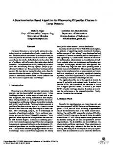
Algorithm Description 1. One dimensional case Assume that one moving transmitter A (possible a satellite) and one receiver B are positioned on a one-dimensional axis as pictured in figure 1.
In the early 1970s J. Glish, proposed a closed form solution for a Doppler Satellite Navigation system [5], based on the early work proposed by R. R. Newton [4]. However, J. Glish does not present the expected accuracy of his approach.
We further assume that the receiver B is perfectly synchronized with the transmitter A and that the initial location of the receiver B is k known. As in [8], let d AB denote the distance between the moving transmitter A and the moving receiver B at discrete time k. Assume that the receiver B moves towards the k transmitter A by the amount of v AB . This is analytically determined from,
The Doppler measurements were also combined with the range measurements to yield an instantaneous positioning with a single satellite [6]. This same idea is used by N. Levanon to produce user terminal position instantly by a two-communication system between a user terminal on the earth surface and a single low earth orbit (LEO) [7].
k k +1 k . v AB ≅ d AB − d AB
Since the Doppler measurements are less noisy, an algorithm, which would produce the user's position based only on Doppler, would be very desirable. In [8] we have proposed an alternative algorithm that uses the Doppler measurements for fixed pseudolites.
(1)
Assuming that the observations are performed at 1 Hz rate, relationship (1) gives the formula for approximating the average velocity during 1 sec interval. Under the above assumptions we can rewrite (1) is accordance with,
(
)
k v AB ≅ x Bk +1 − x Bk − x kA+1 − x Ak .
This expression enables us to form the navigation equation for the one-dimensional case, which can be written as,
Range rate or Doppler Ak
k+1
A
O
B
k+1
B
(2)
k
(
)
k x Bk +1 ≅ x Bk + v AB + x kA+1 − x Ak .
(3)
It is evident in this case that by knowing the Doppler at any epoch we can determine the
Figure 1: One-dimensional system diagram 483
location of the receiver B with perfect accuracy in the one-dimensional case.
k +1 and d BC respectively. Similar to the onedimensional case the receiver C moves towards transmitters A and B by the amount of:
Note: The same expression can be obtained when the receiver B moves away from transmitter A with the only modification of (3): k the plus sign, (+), in front of v AB now becomes minus, (-).
(4)
k k +1 k . v BC ≅ d BC − d BC
(5)
The new point C k +1 is found from the intersection of two circlesone with center at transmitter A k +1 and with radius given by (6) and the other circle with center at the transmitter B k +1 and with radius given by (7). The analytical expression of these distances can be written as,
2. Two dimensional case Assuming an error free environment with perfect synchronization between the transmitters and the receiver, at least two moving transmitters A and B are required to determine the correct location of a single receiver C in a two-dimensional plane (see figure 2). We will again assume that the two transmitters are moving with the coordinate system under consideration. We will also assume that the initial location of receiver B is known. Similar to the two dimensional case in [8], it can be shown analytically that for moving transmitters A and B and for known distances AC and BC there are two solutions in which C can be located.
k +1 k k , d AC ≅ d AC + v AC
(6)
k +1 k k . d BC ≅ d BC + v BC
(7)
Without showing all the work the solution for the new location of the receiver C is determined from: xCk +1 = AyCk +1 + B , y Ck +1 =
Doppler
Y
k k +1 k , v AC ≅ d AC − d AC
Ck
(8)
− b ± b 2 − ac a
,
(9)
where,
Ck+1
A=
Ak+1
y kA+1 − y Bk +1 x Bk +1 − x kA+1
,
(10)
Bk Ak
X
O
B=
k+1
B
2
(
−C
x Bk +1
− x kA+1
),
(11)
k k k k − d BC + v AC − v BC + D , (12) C = d AC
C’k+1
( ) − (x ) + (y ) − (y ) ,
D = x Bk +1
2
k +1 2 A
Figure 2: Two-dimensional system diagram
(
484
(13) (14)
)
(15)
b = A B − x kA+1 + y kA+1 , c = B − x kA+1
k +1 2 A
a = A2 + 1,
(
Both points ( C k +1 and C ' k +1 ) are symmetrical with respect to the line that passes between A k +1 and B k +1 as supposed to A and B [8] (see figure 2). Denote that the new ranges between k +1 the receiver C and transmitters A and B as d AC
k +1 2 B
) + (y ) 2
k +1 2 A
k k . (16) − d AC − v AC
In order to resolve the double location ambiguity we use theorem 1 [8]. Therefore, the correct yCk +1 should be chosen from the two solutions of (9) if, k +1 ≤ rcrk ≤ d Ck +'C1 . d CC
Doppler k
D
k+1
D
(17)
k+1
A
Bk+1
where, denotes the radius (equals the sum Doppler measurements, see 17) of the circle inside of which the receiver, C, is found, rcr
k k , rcrk = v AC + v BC
C
Ak
k+1
k
B
k
C
(18)
k +1 denotes the distance between the current d CC
position and the new correct position of receiver by, such as k +1 d CC
=
(
xCk +1
−
) +(
2 xCk
y Ck +1
−
)
2 yCk
,
Figure 3: Three-dimensional system diagram The new point D k +1 is found from the intersection of three spherical surfacesone with its center at transmitter A k +1 and with radius given by (21), one circle with its center at the transmitter B k +1 and with radius given by (22), and the final circle with its center at transmitter C k +1 and with radius given by (23),
(19)
k +1 denotes similarly the distance between the d CC
current position of the receiver and the mirror image of the new, correct position of the receiver, in accordance with, d Ck +'C1 =
(x
k +1 C
− xCk
) + (y 2
k +1 C'
− y Ck
)
2
.
(20)
3. Three dimensional case In a error free and perfect synchronization environment, the correct location of the moving receiver D in three dimensions can be determined with help of the three moving transmitters (A, B, and C), which are not in the same line at any time as shown in figure 3. Denote that the new ranges between receiver D k +1 k +1 and transmitters A, B and C are d AD , d BD , and k +1 d CD respectively (see figure 3). Similar to the one-dimensional and two-dimensional cases the receiver D moves towards transmitters A, B, and C by the amount of, k k +1 k , v AD ≅ d AD − d AD
(21)
k k +1 k , v BD ≅ d BD − d BD
(22)
k k +1 k . vCD ≅ d CD − d CD
(23)
k +1 k k , d AD ≅ d AD + v AD
(24)
k +1 k k , d BD ≅ d BD + v BD
(25)
k +1 k k . d CD ≅ d CD + vCD
(26)
Without showing all the work the solution for the new location of the receiver D is determined from: x Dk +1 = d1 z Dk +1 + e1 ,
(27)
y Dk +1 = d 2 z Dk +1 + e 2 ,
(28)
z Dk +1 =
− b3 ± b32 − a 3 c3 a3
,
(29)
where, a3 = d12 + d 22 + 1 ,
(30)
b3 = d1e1 + d 2 e 2 − d1 xCk +1 − d 2 y Ck +1 − z Ck +1 , (31)
485
c3 = e12 + e 22 − 2e1 xCk +1 − 2e2 y Ck +1 − A3 ,
(
) (
),
(33)
) (
),
(34)
b z k +1 − z Bk +1 − b2 z Ck +1 − z kA+1 d1 = 2 1 C a1b2 − a 2 b1 d2 = 2
(
a 2 z Ck +1 − z kA+1 − a1 z Ck +1 − z Bk +1 a1b2 − a 2 b1
4. Multidimensional noisy (final) case
(32)
The expressions for the LSA solution utilizing DD pseudorange obtained for the multiple range sources is similar to that obtained in [8]. We take the time here, however, to explain some important differences of modifying the Doppler based navigation algorithm for satellites.
(
)
(35)
(
)
(36)
First we note that the satellites' range vector from the center of the earth can be expressed based on the Taylor series expansion as,
(
)
(37)
! [k ] + 0.5R !! [k ] + O !R !![k ] , (49) R[k + 1] = R[k ] + R
),
(38)
a1 = 2 xCk +1 − x kA+1 , a 2 = 2 xCk +1 − x Bk +1 , b1 = 2 y Ck +1 − y kA+1 ,
(
b2 = 2
y Ck +1
−
y Bk +1
(
)
(39)
(
)
(40)
c1 = A1 − 2 z Dk +1 z Ck +1 − z kA+1 , c 2 = A2 − 2 z Dk +1 z Ck +1 − z Bk +1 , e1 =
b2 A1 − b1 A2 a1b2 − a 2 b1
e2 =
a1 A2 − a 2 A1 a1b2 − a 2 b1
,
(41)
,
(42)
(
!! [k ] , and !R !![k ] are the where, R[k ] , R! [k ] , R satellite's range, range rate, the rate of range rate, and third derivative of range respectively, from the center of the earth at the kth epoch. The quantity O(!R!![k ]) denotes the remainder of the Taylor series expansion for range derivative terms of orders higher than the third. Expression (49) assumes a 1-Hz data rate. A similar expression can be obtained for the range vector between the moving satellite and the user as,
(
!! [k ] , and !R !! [k ] are the where R U [k ] , R! U [k ] , R U U satellite's range, range rate, the rate of range rate, and third derivative of range respectively, from the user U at the kth epoch. The only observable quantities of expression (50) are the range and the range rate utilizing any commercial receiver in the market. The challenge in this case is to derive a quantity from Doppler measurement imitating the raw pseudorange measurements. In order to accomplish that, we first estimate the range knowing the initial location of the receiver and the location of the satellites. Next, the range rate can be replaced with the Doppler measurements. The rate of the range rate can be approximated with successive differences of Doppler. Finally, a process noise sequence can serve as the remainder of the Taylor series expression O(!R!!U [k ]) (see (50)). The result of this work would be the expression for the
k k k k + v BD − d CD − vCD + B2 ,(44) A2 = d BD
(45)
( ) − (i ) , (46)
B1 =
∑
B2 =
∑
i k +1 2 C i= x, y , z
B3 = −
k +1 2 A
( ) − (i ) , (47)
i k +1 C i = x, y , z
∑
2
k +1 2 B
( )
2 i k +1 i = x, y , z C
) , (50)
! [k ] + 0.5R !! [k ] + O !R !! [k ] R U [k + 1] = R U [k ] + R U U U
k k k k + v AD − d CD − vCD + B1 , (43) A1 = d AD
k k + vCD − B3 , A3 = d CD
)
. (48)
Expression (20) can serve as a criterion for selecting the correct z Dk +1 .
486
Doppler derived pseudorange vector, which looks like,
Simulation Simulation results are provided for one moving scenario.
ˆ [k ] + φ! [k ] ρU [k + 1] = R U U + 0.5(φ! U [k ] − φ! U [k − 1]) + w U [k ] .
The satellite constellation can generated using either almanac data or ephemeris data [10]. However, for simplicity the simulation results were obtained for a GPS constellation driven by almanac data. The moving scenario, depicted in figure 4, was selected from one the indoor geo-location applications [6].
(51)
Based on formulation (51) for the Doppler derived pseudorange we can derive an expression for the noise quantities as, σ ρ = 3σ φ! + σ w .
(52)
Table 1: Estimated Doppler measurement noise Item
SAT1
SAT2
SAT3
SAT4
d (cm/s)
0
0
0
0
S (cm/s)
5
7
9
11
The expression of Doppler derived pseudorange (51) is then used to compute the user solution for either the conventional or modified LSA [8].
Figure 4: Satellite, moving receiver layout
Error Sources
•
The error sources affecting the Doppler measurement can be classified in four categories: ionosphere, troposphere, receiver measurement noise, and multipath. Although extensive study of the ionosphere and troposphere models are done by J. A. Klobuchar [11] and J. J. Spilker Jr. [12], a model which performs correction of both the ionosphere and troposphere effects for a single frequency receiver is yet to come.
First we process the raw pseudorange using the CLSA and obtain the lateral and vertical position error for pseudorange measurement error (1 sigma) ranging from 0.01 to 5 m (see figures 5 and 6).
The Doppler receiver measurement noise was estimated and the result of this work is shown in Table 1, where d denotes the sample mean and S and standard deviation.
•
•
Raw pseudorange CLSA
Raw pseudorange MLSA
Next we process the raw pseudorange measurements utilizing the modified least square algorithm (see figures 7 and 8). Doppler derived pseudorange CLSA
Next, we process the Doppler derived pseudorange and obtain the lateral and vertical position error for Doppler measurement error (1 sigma) ranging from 0.01 to 0.1 m (see figures 9 and 10).
It is conceivable that the effect of the multipath and ionosphere, troposphere, and multipath are included in the Doppler measurement noise estimate.
487
Figure 5: Lateral position error vs. pseudorange measurement error
Figure 8: Vertical position error vs. pseudorange measurement error
Figure 9: Lateral position error vs. Doppler measurement error
Figure 6: Vertical position error vs. pseudorange measurement error
Figure 7: Lateral position error vs . pseudorange measurement error
Figure 10: Vertical position error vs. Doppler measurement error •
Doppler derived pseudorange MLSA
Here, we repeat case III only utilizing the modified least square algorithm and the results are presented in figures 11 and 12.
488
References
Figure 11: Lateral position error vs . Doppler measurement error
Figure 12: Lateral position error vs. Doppler measurement error
[1]
W. H. Guier and G. C. Weiffenbach. "A Satellite Doppler Navigation System." Proc. IRE, vol. 48, pp. 507-516, April 1960.
[2]
G. C. Weiffenbach. "Measurement of the Doppler Shifts of Radio transmissions from Satellites." Proc. IRE, vol. 48, pp. 750-754, April 1960.
[3]
R. R. Newton. "Applications of Doppler Measurements to Problems in Relativity, Space Probe Tracking, and Geodesy." Proc. IRE, vol. 48, pp. 754-758, April 1960.
[4]
R. R. Newton. "Everyman's Doppler Satellite Navigation Sysem." IEEE Trans. AES, Vol. AES-3, No. 3, May 1967, pp. 527-554.
[5]
J. Clish. "A Closed-Form Solution for Doppler Satellite Navigation." IEEE Trans. AES, Vol. AES-3, No. 3, September 1971, pp. 875-878.
[6]
B. Parkinson et al. "A History of Satellite Navigation." Proceedings of the 51st Annual Meeting, June 5-7, 1995, Colorado Springs, Colorado.
[7]
N. Levanon. "Instant Active Positioning with One LEO Satellite." Navigation: Journal of The Institute of Navigation, Vol. 46, No. 2, Summer 1999.
[8]
I. F. Progri and W. R. Michalson. "An Innovative Navigation Algorithm Using a System of Fixed Pseudolites." Proceedings of the National Technical Meeting of the Satellite Division of the ION, 2001, January 22-24, 2001, Long Beach, California.
[9]
T. P. Yunck. Orbit Determination, Chapter 21 of Global Positioning System: Theory and Applications, Volume II. Edited by B. W. Parkinson and J. J. Spilker Jr & Associate Editors P. Axelrad and P. Enge, The Institute of Aeronautics and Astronautics, pp 559-592.
Summary and Discussion It appears that the CLSA algorithm provides erroneous lateral and vertical position for the user despite the pseudorange or Doppler measurement error. For a constellation of 10 satellites and a system PDOP of closer to 1, obviously the geometry is not the primary deteriorating source of the navigation solution. A detailed discussion of this phenomenon will be the object of another article. We just mention here that it appears from the simulation point of view that the method under observation is incorrect. On the other hand, the MLSA algorithm appears to provide consistent results with pseudolite data only [8]. Thus, processing Doppler derived pseudorange and utilizing the MLSA algorithm yields a navigation solution 50 times better than the pseudorange MLSA. 489
[10] J. J. Spilker Jr. GPS Navigation Data, Chapter 4 of Global Positioning System: Theory and Applications, Volume I. Edited by B. W. Parkinson and J. J. Spilker Jr & Associate Editors P. Axelrad and P. Enge, The Institute of Aeronautics and Astronautics, pp 121-176. [11] J. A. Klobuchar. Ionospheric Effects on GPS, Chapter 12 of Global Positioning System: Theory and Applications, Volume I. Edited by B. W. Parkinson and J. J. Spilker Jr & Associate Editors P. Axelrad and P. Enge, The Institute of Aeronautics and Astronautics, pp 485515. [12] J. J. Spilker Jr. Tropospheric Effects on GPS, Chapter 13 of Global Positioning System: Theory and Applications, Volume I. Edited by B. W. Parkinson and J. J. Spilker Jr & Associate Editors P. Axelrad and P. Enge, The Institute of Aeronautics and Astronautics, pp 517546.
490