stress measure associated with the rate of strain D (Simo J.C. [30]). As we choose a hypoelastic law, we have to take into account an objective rate of stress, ...
Numerical Formulation for solving Soil/Tool interaction problem involving Large deformation.
Nicolas Renon, Pierre Montmitonnet, Patrick Laborde.
Key words: Soil Mechanics, Ploughing, Finite Element, Compressible Plasticity.
Abstract Soil ploughing as used for military breaching induces very large deformation (flow) of a generally compressible plastic medium with large structural rearrangement and mechanical properties evolution. So modelling such a process requires to handle numerically the non-linearities induced by the material and by unilateral contact and friction between the rigid structure and the soil. Moreover, the different sizes of tines and blade make it a two-scale process, thus requiring large numbers of d.o.f’s in FE simulations. Reaching a steady state takes a displacement several times the typical dimension of the ploughing system, so that between a few hundred and many thousand time steps are necessary. We present the description of the global model and the implementation of a one-phase, critical state compressible non-associated plastic law [4]. The numerical platform is the large deformation FE software Forge3®, initially devoted to metal forming. Then we focus on simulations of a single tine ploughing different kinds of soil. Results obtained for complex tools involving several tines and/or a blade will be presented in another paper.
1 - Introduction The aim of this work is to provide a global 3D FE model devoted to the modelling of superficial soil ploughing in the large deformation range and for a vast class of soil treatment tools. One of the most complex soil ploughing tool, for example, is involved in military breaching. This process consists in scraping off a ca. 30 cm superficial layer of soil (for cohesive soils) or combing mines off it (for noncohesive frictional soils, e.g. sand). A plough is used for this purpose, consisting in a V-blade with sharp tines, pushed by a caterpillar vehicle. Especially in this case, more generally in ploughing studies, the question is: what is the force necessary to push the plough, and, for military breaching, is the soil / caterpillar contact able to transmit it ? What is the soil response depending on soil nature and tool geometry ? Modelling such processes faces several crucial points to determine accurately soil reaction and deformation fields : 1. The interacting system consists of two materials, soil and metal, with complex interface geometry. The heterogeneous and stratified nature of the soil adds further complexity. 2. The cutting process creates a flow of the soil and large deformations, hence a permanent geometric evolution of the unconstrained boundary (free surface). 3. The behavior of surface soils under combined low stress state (free boundary) and large deformations is poorly known, all the more as vegetation (roots) has to be considered. 4. And so is the soil / metal interface friction. 5. This is typically a two-scale problem, where deformation occurs at the tine tip vicinity (a centimetre scale) and at the scale of the blade (metre scale) which pushes a heap of extracted material. Numerical simulation of such a problem can go back to the soil structure, namely its particulate character, using a granular model like the DEM (distinct element method), now widely spread in geomechanics. It is clearly adequate for purely frictional soils (sands); some kind of cohesion can be 2
introduced, although not in a straightforward way, so that this remains a debated matter. Numerical simulation of the problem under investigation has been carried out with a DEM for a single tine in 2D and 3D [25]. Quite intensive computations were necessary to examine the characteristics of this “small geometric scale”, which makes intractable the two scale problem involved in blade-tine interacting system: either the particles will be too many, or they will be too big for the small-scale part of the system (tine tip vicinity). The same difficulties arise for the alternative, continuum FEM modelling, but the mesh size can here be locally adapted. Literature does provide FEM studies of soil ploughing [12],[22],[23]. Usually, they address agricultural purposes, tools consist of either a single tine or a smooth blade. Simulations are often 2D and flow patterns are prescribed, with adjunction of joint element at the tip of the tool for instance [22]; large deformations, in terms of mechanical formulation as well as free surface evolution, are not really dealt with. In most continuum approaches, a soil is idealised as an elastic-plastic body, using classical soil mechanics models such as Mohr-Coulomb or Drücker-Prager [22]. More recent alternatives include hypo-plasticity [17],[35]. In this paper, the elastic-plastic CJS model (which stands for Cambou-Jafari-Sidoroff model [5]) has been chosen: based on the critical state concept, it can handle the large deformation response of soils under tri-axial solicitations, namely, hardening (densification) and/or softening (dilatation). Our developments for the numerical resolution of the evolution problem corresponding to the plowing process modelling, is based on a 3D FE software devoted initially to metal forming, namely Forge3®. This software can take into account large mesh distortion, consequence of large displacement tool, thanks to an automatic re-meshing routine. Crucial non linear points in the plowing modelling exposed above, can be sum up at the numerical stage as : unilateral frictional contact, non associated plasticity and large deformation in terms of change in free surface and stress strain measures. The numerical resolution is performed through an incremental time decomposition with the Updated Lagrangean procedure. In our case, penalization of contact conditions and mesh distortion point out a rather low 3
upper bound for time step size, and consequently the incremental tool displacement cannot exceed 1mm. Practically, if we compare this incremental displacement to the military breaching plough dimension, about 5 meters in width for the blade, and 3 cm wide 30 cm deep for the connected tines, time step can be considered as small. As our aim is to perform a robust 3D numerical model in the context of highly intensive computations, able to model plowing application for different soil treatment tools, we are lead to make proper relaxation of a part of the non linearities involved in the numerical problem. Hence the first part of the paper is devoted to the presentation of the global mechanical problem and large deformation, followed with attention on linearisations made in order to provide eventually the numerical model. We present also the space and time discretisation, frictional contact modelling, general elasto-plastic law and resolution algorithm. The validation of CJS implementation is presented by comparison with results from Flac2D©, 2D explicit FE software, on triaxial experiments with a set of previously identified model parameters. The second part of the paper is devoted to the investigation of numerical simulation for a single tine. Some influent parameters are discussed as well as soil nature influence. Finally, the conclusion evokes results for multi-tine tool simulations, to be presented in details in another paper.
4
2 - Global Model Description 2.1 Strain and stress measures Let ψ : Ω × [0, T ] → IR 3 be the deformational motion of the continuum body with reference configuration Ω , time interval of interest [0, T ] and particles labeled by X ∈ Ω . For a time
t ∈ [0, T ] , the current configuration of the domain occupied by the soil, theoretically semi-infinite, is defined by Ω (t ) = ψ (Ω, t ) with current particles x = ψ ( X , t ) ∈ Ω (t ) . To describe the inelastic response in large deformation Lee and Liu [18] introduce the multiplicative split of the deformation gradient, F ( X , t ) = ∂ψ ( X , t ) / ∂X into elastic part F E and plastic part F P :
F ( X , t ) = F E ( X , t )F P ( X , t ) A suitable definition of strain rate can then be introduced by considering the spatial velocity gradient
l which is expressed as
(
)
( )
−1 −1 −1 −1 l = F&F −1 = F& E F E + F E F& P F P F E = l E + F E l P F E
If we assume that the elastic transformations (strain and rotation) are negligible compared to the plastic one, it appears reasonable to consider the elastic stretch tensor V E to be given by
V E = I + ε E where ε E is the infinitesimal elastic strain tensor and F E = V E . Following Lee and Liu [18] and neglecting higher order infinitesimal quantities, one can arrive at the following approximation
sym[l ] = D ≅ D E + D P
(1)
Assumption above made on the amount of elastic strain compared to plastic strain, is usual in metal plasticity. Especially in forming processes the material undergoes large plastic transformation as well as in metal powder compaction where the material is compressible and often idealised though classical soil mechanics models. Hence strong numerical as well as experimental arguments make reasonable to classify the process of soil plowing in this context. Moreover, the kinematics of the plowing process 5
can be closely related, in another scale range, to the cutting process for metals [11] or the scratching of organic glasses [4], where elastic transformations are small compared to plastic transformation. Hence in the following, we will make use of the additive decomposition eq.(1), coupled with an hypo-elastic stress rate – strain rate constitutive equation. As a stress measure we consider the Kirchhoff stress tensor τ = Jσ where J = det F and σ is the Cauchy true stress tensor. In the case of incompressible plasticity it is common to approximate
(
( ) )
Kirchhoff stress by Cauchy stress det ( F ) = det F E = 1 . But, in our plastically compressible case this approximation cannot be made. We remark that Kirchhoff stress tensor is an energy conjugate stress measure associated with the rate of strain D (Simo J.C. [30]). As we choose a hypoelastic law, we have to take into account an objective rate of stress, which leads to the following relation between the elastic part of the strain rate and an objective rate of Kirchhoff stress: ∇
D E = Lτ
(2)
with L elastic compliance tensor. The superscript ∇ above a symbol refers to an objective timederivative involving rotation terms given by the spin tensor (see for example Ponthot J.P. [26] ). The properly speaking plastic constitutive equations given below describe the yield criterion and the general flow rule, with complementarity (Kuhn-Tucker) conditions for the elastic-plastic transition (N is the number of plasticity surfaces): N ∂g D P = ∑ λ&i i (τ , R ) ∂σ i =1
λ&i ≥ 0;
(3)
f i (τ , R ) ≤ 0; λ&i f i (τ , R ) ≡ 0 ; i = 1, K , N
Yield surfaces fi may differ from their plastic potentials gi . Finally, the evolution law of internal variables R = (Ri )1≤i ≤ q can express isotropic hardening as well as softening in a condensed form such as : 6
R& = Ψ (τ , R , D )
(4)
A precise description of constitutive equation of CJS model implemented will be given in section 3.
2.2 Mechanical problem Whether the displacements or strains are large or small the equilibrium conditions between external and internal forces have to be satisfied. Thus, the equilibrium equation can be written on the current configuration Ω(t ) , in a standard form as:
divσ + ρg = ργ
(5)
where σ is the total stress, ρ (scalar) soil density, γ the acceleration and g the gravity. The last two terms have to be maintained as their order of magnitude is similar to the constitutive stresses. The analysis is restricted to the soil, i.e. the tool is supposed rigid. Subscripts T and n denote tangential and normal components, n is the external normal to the boundary ∂Ω(t ) . Crucial boundary conditions mainly include unilateral contact and friction. For the former, Signorini’s condition is written in terms of velocities on the contact surface ΓC(t ) ⊂ ∂Ω(t ) :
( v − v tool ).n ≤ 0;
σ n ≤ 0;
(6)
σ n ( v − v tool ).n ≡ 0 with σ n = σn ⋅ n the normal stress component and vtool the prescribed velocity of the rigid tool. In the present model, the singularities in inequalities above are relaxed by the penalty method :
σ n = −θ (v − v tool )⋅ n
+
on ΓC(t )
(7)
brackets + means that the repulsion stress in (7) is applied only if penetration occurs :
(v − v )⋅ n < 0 .Then θ is the “large” penalty parameter. tool
7
The displacement formulation of Signorini’s condition is the most widely spread in literature for quasistatic approach in solid mechanics [37]. Velocity formulation appears to be more suitable in evolution problems, at least from a numerical point of view. However in terms of incremental time steps, both are equivalent. The friction threshold law is replaced by a one-to-one regular relation:
σ T = −π T
vT − vTtool
β F + vT − v
tool 2 T
on ΓC (t )
(8)
where σ T = (σn )T is the tangential stress and π T is the friction stress: π T = µσ n for Coulomb’s law and π T = m k for the friction factor model (k is the shear yield stress). Parameter β F is a “small” regularisation term. Finally the velocity field is equal to zero on ΓD (t ) ⊂ ∂Ω(t ) , in order to reduce the semi-infinite domain to a finite one. On ΓN (t ) ⊂ ∂Ω(t ) , the complementary part of ΓD (t ) ∪ ΓC (t ) , normal stresses are equal to zero (free surface) :
σn = 0
on ΓN (t )
8
(9)
2.3 Variational formulation To derive the variational formulation of equilibrium equation, at time t, we multiply terms of (5) by a kinematically admissible virtual velocity field, and integrate over the current configuration domain. We finally obtain, thanks to Green’s formula, the following variational formulation of the possible dynamic equilibrium taking into account frictional contact
∫ ργ ⋅ wdV + ∫σ : ε ( w) dV − ∫σ
Ω (t )
()
Ω (t )
n
⋅ wn dS −
ΓC t
∫σ
()
T
⋅ wT dS =
∫ ρg ⋅ w dV
Ω (t )
ΓC t
∀w∈V0 (t )
(10)
where σ n and σ T are defined in equations (7) and (8), V0 (t ) is the set of velocity field vanishing on ΓD(t ) . At this stage stress and strain-rate measures are Eulerian and σ can be interpreted as the Cauchy stress tensor. Applying the symmetric gradient operator ε (⋅) to the velocity field w of the current configuration, we have ε (w ) = D * , which can be interpreted as a virtual strain rate. A variational formulation of the isotropic non associated plasticity set of equations (1)-(4) can be written as follows:
L τ∇ − D : (π − τ ) dV ( ) τ ∈ P R ; Ω (t ) R& = Ψ (τ , R, D )
∫
≥0
∀π ∈ E (τ , R ) (11)
Where plasticity convex P (R ) and set of the iso-potential surfaces E (σ , R ) , are defined below:
P ( R ) = {π : f i (π , R ) ≤ 0; i = 1,K, N } E (τ , R ) = {π : g i (π , R ) ≤ g i (τ , R ) ; for i such that f i (τ , R ) = 0 } The presentation of the set of variational equation in an Eulerian form have the interest to provide a quite simple and synthetic formulation of the plowing problem involving unilateral frictional contact, 9
non associated multisurface plasticity and large deformation. Nevertheless, our aim is to perform a 3D numerical model in the context of highly intensive computations, able to model plowing applications for different soil treatment tools, variable in size and geometry. To that end we will adopt a step by step approach based on time increments decomposition, i.e. [t , t + ∆t ] , in order to numerically handle this evolution problem. In this context, we developed a formulation in the Updated Lagrangean framework with the configuration at the beginning of time step as the reference configuration. This approach need to re-write the governing equations of the mechanical problem in the Lagrangean frame. Moreover, such Lagrangean formulation lead, among other, to provide a proper and consistent formulation of the hypo-elasoplastic constitutive relation which add non linearity to the problem (see for example [7],[36]). On the other hand, at numerical point of view, the Updated Lagrangrean description allows to relax a part of the non-linearity due to large deformation, typically in the choice of lagrangean strain and stress measures (Piola-Kirchoff stress tensors and Green Lagrange strain tensor [6]). Hence, in the present paper and for the sake of simplicity we focus on the approximations associated to this approach and their justifications, in order to eventually provide the numerical model actually solved. 2.4 Updated Lagrangean and Approximations Approximation and linearisation that might be done, are related to time step size, but have to guarantee that the kinematics underlying large transformation is eventually addressed. Hence significant differences may appear in numerical simulation with Total or Updated Lagrangean formulations, see for example [15]. In our case, independently from material large deformations, the time step size is principally governed by (i) penalized contact conditions, which imply a rather low upper bound on time step size, and (ii) by mesh distortion. Practically the corresponding incremental displacement of the plowing tool cannot exceed 1 mm. This justifies the following approximation made on stress and strain measures. Hence over the time step [t , t + ∆t ] we assume that the current and reference configuration are close enough (the change in volume remains small) and use the Cauchy stress tensor 10
as the stress measure in the constitutive equations as well as in the equilibrium equation. Correspondingly the strain measure is the infinitesimal strain tensor. However small time steps do not make the objective derivation equivalent to material derivatives ; such an approximation would lead to erroneous numerical results, especially in the direction of stresses after numerous increments. In our incremental formulation, see equation (12) below, the stress σ approx . is first computed with a nonobjective, material time-derivative, and a correction is performed at the updating stage, taking
σ = W T σ approx .W , with W the total (infinitesimal) rotation tensor (in the following the mention approx. will be omitted). Finally the Updated Lagrangean procedure lead to integrate on the reference configuration denoted Ω t . These considerations allow us to describe the set of equation that are actually numerically solved.
2.5 Incremental Formulation As we approximate the problem through time steps, we have to apply an integration scheme to the set of governing equations, especially for the constitutive law. To that end a Forward Euler scheme is applied for the geometry actualisation and a Backward Euler scheme for the constituive equations. We recall that hypoelastic relation involves simply a material time-derivative of stress (the rotation terms being corrected for only at the updating stage, see above) and so we can derive the incremental variational formulation of both equilibrium and constitutive equation. With the notation
∆y = y t + ∆t − y t , the global incremental problem consists in finding the velocity field v t + ∆t ∈ V0t , the stress field σ
t + ∆t
t +∆t
and the internal variables R
satisfying the variational system (12)-(13).
11
∫ ρ ∆∆vt ⋅ wdV + ∫σ
Ω
t
Ω
t + ∆t
: ε ( w) dV −
∫σ
t + ∆t n
⋅ wn dS −
ΓCt
t
∫σ
t + ∆t T
⋅ wT dS
ΓCt
=
∫ ρg ⋅ w dV Ω
(
)
∫(
(
)) (
)
(
))
∀w ∈ V
t
σ t + ∆t ∈ P R t + ∆t ; L σ t + ∆t − σ t − ∆tL−1ε v t + ∆t : π − σ t + ∆t dV ≥ 0 t Ω t + ∆t , R t + ∆t , ε v t + ∆t ∆R = ∆tΨ σ
(
(12) t 0
(
∀π ∈E σ t+∆t , Rt+∆t
)
(13)
with V0t the set of velocity field vanishing on ΓDt , and the normal and tangential stresses given by
σ
t + ∆t n
= −θ d
t + ∆t
−δ
+
and σ
t + ∆t T
= −π
t T
vTt + ∆t − vTtool
β F + vTt + ∆t − vTtool
(
2
)
with the incremental distance function given by d t + ∆t = d t + ∆t v t + ∆t − v tool ⋅ n t and the smoothing corner parameter δ allowing a (small) penetration. Repulsion stress is applied if the distance inside the tool is larger than δ.
Hence contact conditions (non-penetration) are written at the end of the time step, but the normal involved in the computation of d is taken at the beginning of the current time step. Similarly, in the case of Coulomb’s friction model, we use the normal stress at the beginning of the current time step,
σ nt . These two approximations avoid the computation of complicated, dissymmetry-enhancing derivatives for the stiffness matrix,. This is a further reason for taking small time-steps; otherwise the neglected stiffness terms (e.g. ∂n / ∂v ) become significant and convergence may be degraded.
12
2.6 Mixed Formulation The solution of the inequation (13) is locally equivalent to the projection of an elastic predictor on the plasticity convex :
σ t + ∆t = ProjP (R ){σ t + ∆tL−1ε (v t + ∆t )} t + ∆t
This projection operator is identity when the elastic predictor remains inside the convex of plasticity. Directions of projection depend on the potential gradient and the elastic inner product. The main non linearity of this operator is that projection depend also on the solutions, namely σ t +∆t and Rt+∆t .
Thanks to this local projection operator we can build a mixed velocity/pressure formulation of the problem. We first introduce the following notations for hydrostatic pressure (spherical stress)
p = − 13 tr (σ ) ; deviatoric stress s = σ + p1I ; and deviatoric strain rate e(v ) = ε (v ) − 13 tr (ε (v ))1I . Using the definition of pressure and thanks to the additive decomposition of strain rate we have:
( )
( )
pt+∆t = pt −K tr ∆ε + Ktr ∆ε P
(14)
( ) the volumetric plastic deformation at the end of time step.
K is the bulk elastic modulus and tr ∆ε
P
13
To perform velocity/pressure formulation we enforce weakly equation (14), which leads to the following system :
v t + ∆t ∈V0t ; t + ∆t t + ∆t t + ∆t t + ∆t ∆v ρ ⋅ wdV + s : e( w) dV − p tr (ε ( w) )dV − σ n wn dS − σ T ⋅ wT dS t ∆t t t ΓCt ΓCt Ω Ω Ω = ρg ⋅ w dV ∀w ∈V0t (15) t Ω ∀q ∈ Q p t +∆t − p t + K tr ∆ε − tr ∆ε P q dV = 0 t Ω
∫
∫
∫
∫
∫
∫
∫{
( ( ) (
[
{
) )}
(
with s t + ∆t = ProjP (R t +∆t ) σ t + ∆tL−1ε v t + ∆t
)}] ; [ ] d
d
refers to the deviatoric part and Q is the set of
sufficiently regular virtual pressures.
14
2.7 Spatial Discretisation We briefly present the spatial discretisation performed with velocity/pressure finite element P1+/P1 [1],[3]. Linear shape functions for velocity are enriched with a bubble function at the centre of the tetrahedron. Bubble shape functions are linear over each of the 4 sub-tetrahedra constructed with the centre of the element. Let
ε
h
be a triangulation of Ω t into tetrahedra, the velocity field is additively decomposed as follows:
wh = vh + bh
∈
v
h
⊕ Βh =
w
(16)
h
with interpolation spaces:
v
h
3 3 = v h : v h ∈ (C 0 (Ω h )) and v h ϖ ∈ ( P1(ϖ h )) , ∀ϖ h ∈ ε h h
Β h = bh : bh ∈ (C 0 (Ω h )) , bh = 0 on ∂ϖ h , ∀ϖ h ∈ ε h , bh ϖ ∈ (P1(ϖ hi )) , i = 1,..,4 3
3
(
h
)
We note C 0 (Ω h )
3
the space of continuous functions on Ω h ⊂ ΙR 3 , (P1(ϖ h )) the space of linear
functions on element ϖ h ⊂ ΙR 3 ,
3
Β h the
bubble space included in 4th order polynomial space,
ϖ hi , i = 1,..,4 representing a sub-tetrahedron of the element ϖ h . Bubble functions are continuous and piecewise differentiable.
We describe now the resolution algorithm of system (15) once spatially discretised. Due to the strong non linearity of the local projection operator the resolution of such a system involves two steps (Algorithm 1). The first step is devoted to constitutive equation integration for a given incremental deformation, that is to perform projection. This stage provides total stress and plastic strain, as well as internal variable. The second step consists in solving, in terms of velocity and pressure, equation (15) updated with only deviatoric stress and volumetric plastic deformation, provided by the previous step. Note that the pressure p t + ∆t is a basic unknown of the velocity / pressure formulation and as such is 15
discretized and has to be solved for with global eq.(14), not at elemental level. After convergence, the continuous pressure field computed from the spatially discretised system (15) is equal to the one given by the projection, at the element level. The system (14) is still strongly non linear and we use the Newton-Raphson method with line-search to solve it.
Algorithm 1: Mixed Incremental Resolution 1. Input Data : ∆t , v t , p t , s t , R t , ε& ( ε& is given)
{
}
2. Constitutive equations integration : σ t + ∆t = ProjP (R t +∆t ) σ t + ∆tL−1ε&
(
)
3. Solve equation (15) in v t + ∆t , p t + ∆t , with s t + ∆t , ∆ε P known, with Newton-Raphson 4. Data updating, return 1
We note that the stiffness matrix resulting from Newton-Raphson method is non-symmetric due to both non-associativity and compressibility of the general hypo-elasto-plastic law. This is why the Minimal Residual solver of Forge3® has been replaced here by the Bi-cgstab algorithm [34]. The improvement as compared to using a symmetric solver with a symmetrized stiffness matrix has been previously quantified [28].
In the present application, extensive use has been made of the fully automatic topological mesher and remesher of the software [9]. The remeshing criteria depend on the geometric quality of elements and a local refinement in the vicinity of the tool is specified by a set of element sizes. Each set is associated with a prescribed volume, and in our case such parallelepiped “boxes” move with the tool. After remeshing the former velocity, pressure field and state variables (stress and internal variables) are projected into the new configuration.
16
3 - Integration of constitutive equations
Constitutive model have been derived from the general CJS Model [5]. This elastic-plastic model has been designed as a phenomenological approach for geo-materials.
3.1 Compressible CJS constitutive equation This model involves two yield surfaces, similar to Cap Models: a spherical mechanism represented by a plane closing the elastic domain on the pressure axis (equation (18)) and a deviatoric mechanism
s : s is the second, ( det (s ) the third) stress
represented by equation (19). In the following s II =
invariant. This model accounts for hardening and/or softening responses exhibited by soils for monotonous loadings, associated with densification and/or dilatations. The concepts of characteristic state (separating contractive from dilatative stress states) and critical state (deformation at constant volume, reached after large strain) are also included.
The elastic law is non linear and hypo-elastic :
p& ε& E = 1 s& + 1Ι 2G
with G = G0 ( p )
ne
( p a )− n
e
and K = K 0e ( p )
ne
3K
( p a )− n
e
(17)
pa is a reference pressure equal to 100 kPa, G0,
K 0e , ne are model parameters.
The yield surface of the spherical mechanism is written:
f 1 (s , p , Q ) = p − Q = 0 n −n with Q& = K 0p ( p ) 1 ( p a ) 1 λ&1 .
17
(18)
Note that λ&1 >0 (spherical plastic multiplier); thus, only hardening (increase of Q) is possible in this model. The corresponding flow rule is associated, K 0p is a constant hardening modulus, n1 a parameter.
The yield surface of the deviatoric mechanism is written:
f 2 (s , p , R ) = s II h ( s ) − 3 Rp − H = 0 with h( s ) = 1 − γ 54 det( s ) s II3
(19)
1/ 6
, γ is a parameter of the model allowing the cross section of the yield
surface to evolve between a circle and a rounded triangle approximating the Mohr-Coulomb non regular hexagon. H is the (constant) cohesion, R the average slope of the yield surface, the evolution of which is given below in equations (21) and (22). The model is non associated :
ε&2P = λ&2
with
∂g 2 ∂σ ij
(s , p , R )
(20)
∂f ∂f β ' ( sij s II ) − δ ij , β ' = β − 1 + s II s IIc . Tensor η is = 2 − 2 η kl η ij and η ij = 2 ∂σ ij ∂σ ij ∂σ kl β ' +3 ∂g 2
(
)
a weighted average of the deviatoric stress direction (sij) and the pressure axis direction (δij), and parameter β is a constant (β = 0 means plastic incompressibility). Superscript c stands for “in the characteristic state”. Through (20), the direction of the strain rate (dilatation or contraction) depends on the position of the current stress state (sII) with respect to the characteristic surface f according to:
f c (s , p ) = s II h ( s ) − Rc p < 0 ⇒ contraction
f c (s , p ) = s II h ( s ) − Rc p > 0 ⇒ dilatation
This surface is not a yield surface, it has a different nature from f1 and f 2 .
18
c
(s , p ) = 0 ,
The hardening-softening variable R evolves by :
R=
ARm p Ap + Rm
(21)
with Rm = Rc + µ ln( pc / p ) and p c = p c 0 exp( − c ϑ ) , where ϑ is the relative volume change; A,µ, c(>0) are model parameters, p an internal state variable related to pressure and plastic deformation by:
p p& = − λ&2 p a
−3 / 2
∂f 2 ∂R
(s , p , R )
(22)
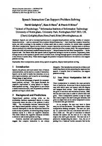
Rm is the radius of the fracture surface, which represents the maximum shearing experienced by the material. Rm converge to the critical state parameter Rc, here equal to the characteristic surface radius. As seen in figure 1, the evolution of R may display a peak or not, depending on initial material density (through p c 0 ) : loose sand will monotonically “harden”, dense sand will first “harden” then “soften”. As p → +∞, R → Rm , and Rm → Rc .
0,4
0,4 Rm 800 D
0,35
0,35
R 800 D 0,3
0,3
0,25
0,25
0,2
0,2
0,15
0,15
0,1
0,1
0,05
0,05
Rm 800 L R 800 L
0
0 0
5
10
15
20
25
30
35
40
axial def. %
0
10
20
30
40
axial def.%
Figure 1: Maximal shear surface radius Rm and yield surface evolution R in a tri-axial test with confinement pressure 800 kPa, Rc = 0.265 (dashed line). Dense sand (D, left), loose sand (L, right).
19
3.2 Implicit scheme For a given incremental strain, we have to perform the incremental projection operator for the set of evolution equation of CJS Model during the time step [t , t + ∆t ] :
σ t + ∆t = Proj P (Q
(
) {
(
t + ∆t
) } {
, R t + ∆t
(
t −1 ) {σ + L ∆ε }
) }
where P Q t +∆t , R t +∆t = τ : f1 τ , Q t +∆t ≤ 0 ∩ τ : f 2 τ , R t +∆t ≤ 0 . To provide such an operator, the implicit formulation of CJS constitutive equations is written below. In the present work, we chose linear elasticity with non pressure dependent bulk and shear modulus. Total incremental plastic deformation is split into its spherical and deviatoric parts.
In the case where both mechanisms are active, and according to the flow rules, the volumetric strain is given by:
(
) (
tr ∆ε P = tr ∆ε 1P + ∆ε 2P
)
∂f ∂p = ∆λ1t + ∆t tr 1 s t + ∆t , p t + ∆t , Q t + ∆t + ∆λt2+ ∆t ∂p ∂σ
(
)
∂g ∂p tr 2 s t + ∆t , p t + ∆t , R t + ∆t ∂p ∂σ
(
)
and shearing (deviatoric) strain by:
∆e P = ∆e1P + ∆e2P =0
∂g + ∆λt2+ ∆t 2 s t + ∆t , p t + ∆t , R t + ∆t ∂s ∂σ ∂s
(
)
Thanks to the plane Cap, both mechanisms interfere only in the compressible part of plastic deformation. Hence, the incremental stress equation is written in terms of spherical and deviatoric parts :
20
t + ∆t ∂g = p t − K tr (∆ε ) − K ∆λ1t + ∆t + ∆λt2+ ∆t 2 s t + ∆t , p t + ∆t , R t + ∆t p ∂p t + ∆t ∂g = s t + 2G∆e − 2G ∆λt2+ ∆t 2 s t + ∆t , p t + ∆t , R t + ∆t ∂s s ∂s ∂σ
(
(
)
)
(23)
The double consistency condition leads to:
f 1 ( s t + ∆t , p t + ∆t , Q t + ∆t ) = p t + ∆t − Q t + ∆t = 0 f 2 ( s t + ∆t , p t + ∆t , R t + ∆t ) = s IIt + ∆t h s t + ∆t − 3 R t + ∆t p t + ∆t − H = 0
(
)
(24)
The non linearity of system (23) in unknows p and s, is partially linked to the third invariant involved in the deviatoric mechanism. More classical models such as Drucker Prager or Cam Clay, lead to a simplified system (23), in which pressure and deviatoric stress at time t+∆t depend only on trial stress and plastic multipliers. The latter appear in system (24) thanks to hardening/softening laws and stress components. They are basic unknowns of the problem. Hence, the projection step consists in :
Find s t + ∆t , p t + ∆t , ∆λ1t + ∆t , ∆λt2+ ∆t satisfying the non linear system (23)-(24).
The numerical resolution of this system follows the general return mapping algorithm. It is well known that numerical difficulties may occur according to, among others, the slope and non linearity of evolution laws. To overcome these numerical difficulties at the local integration step, different techniques are proposed in the literature [2],[10],[14],[19],[33]. Some authors ([2],[19]) replace a full Newton method by a fixed-point like method, which results in a split-level resolution of equations in system (23)-(24). We applied this method to solve the local projection step. However for the present multi-surface plasticity model, we focused on problems where non linearity due to the third stress invariant (function h) can be relaxed. Hence the projection step can be reduced to the resolution of the non linear system (24).
21
Eventually in order to perform the global Newton Raphson method the consistent tangent operator, [29],[31] has been derived.
3.3 Validation on Tri-axial Tests To perform the validation of our implementation in Forge3®, we have compared our results with experiments for loose and dense Hostun sand ; more precisely, we have compared the present implementation of the CJS model with the implementation done previously in the soil mechanic FEM software Flac2D© [13] (figures 2b and 3b), and recalled the comparison of Flac2D© with experiments detailed in [16] (figures 2a and 3a).
Parameter K0 e G0 ne K0 p n1
Loose sand 50×103 kPa 40×103 kPa 0 50×103 kPa 0.6 2.2 0.11×10⁻³ 0.845 30 750 kPa 0.03
β
A
γ c Pco
µ
Dense sand 80×103 kPa 50×103 kPa 0 80×103 kPa 0.6 2.2 0.4×10⁻³ 0.845 30 8×10³ kPa 0.03
Table 1: CJS model parameters for loose and dense Hostun Sand. The set of parameter listed in Table 1 has been used; it is the same set as used in [16], except for the simplifications made in the present implementation (Forge3® is restricted to linear elasticity, so ne = 0). The numerical domain is 1/8th of a cylinder (45 nodes and 102 tetrahedron). Convergence criterion on the global Newton-Raphson’s Method is ε NR = 10 −6 , the iterative solver is Bi-cgstab. Convergence criterion for local integration is ε local = 10 −12 .
22
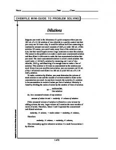
Graphs on Figure 2 and Figure 3 represent results respectively for stress-strain and volumetric-axial strain relations, for three confining pressures 100 kPa, 300kPa, 800 kPa. As a first observation CJS correctly models the experimental stress-strain relation for both densities (figures 2a and 3a). The concept of critical state, here clearly evidenced by experience, is correctly handled: whatever the sand density is, the stress level eventually reached is the same, for each confining pressure. The description of volume variation is not as satisfactory, pointing out severe difficulties met to model the whole range of responses displayed by soils. Nevertheless, mechanisms related to the volumetric variation, namely densification and dilatation, are well represented. Comparisons of Flac2D© and Forge3® results are plotted on Figure 2 and Figure 3 (bottom). In terms of stress-strain relation, the agreement between the two codes is very good. Slight differences appear, mainly in the slope at the beginning of the curves for the 800 kPa confining pressure. These differences are related to the treatment of elasticity, non linear in Flac2D©, linear in Forge3®. In terms of volume variation, more significant differences appear for extreme conditions (loose sand under high pressure and dense sand under low pressure). It is thought that linear elasticity is the reason here also, but how it influences the amount of plastic deformation at the re-projection step is more difficult to understand. Moreover for the stress-strain relation, the concept of critical state will eventually provide, for any elasticity modulus, roughly the same stress level, but the deformation mode will be different. As a whole, the results of the two implementations are rather close to each other and to experiments. As the two software are radically different in all respects (explicit vs implicit formulation, hexaedra vs tetrahedra, …), this tends to prove that the present implementation has been done correctly.
23
2,5 Forge3 100L FLA C2D 100L
2
Forge3 300L
deviatoric stress Mpa
FLA C2D 300L Forge3 800L
1,5
FLA C2D 800L Forge3 100D FLA C2D 100D
1
Forge3 300D FLA C2D 300D Forge3 800D
0,5
FLA C2D 800D
0 0
10
20
30
40
50
axial de f. %
Figure 2: stress-strain relations on tri-axial tests for three confining pressure: 100 kPa, 300 kPa, 800 kPa, for Dense (D) and Loose (L) sand. (Top) comparison experience – Flac2D. (Bottom) comparison Flac2D© – Forge3®.
24
10
5
Forge3 100L FLAC2D 100L Forge3 300L
0 vol. def %
0
10
20
30
40
50 FLAC2D 300L Forge3 800L FLAC2D 800L
-5
Forge3 100D FLAC2D 100D -10
Forge3 300D FLAC2D 300D Forge3 800D
-15
FLAC2D 800D
-20
axial def. %
Figure 3: volumic-axial strain relation on tri-axial tests for three confining pressure: 100 kPa, 300 kPa, 800 kPa, for Dense (D) and Loose (L) sand. (Top) comparison experience – Flac2D. (Bottom) comparison Flac2D© – Forge3®.
25
4 - A simple system: ploughing with a single tine The ploughed superficial soil layer has a very complex behavior, in particular due to the large heterogeneity of the soil structure, basically a granular solid influenced by pore water pressure, maintained or not by a root network, more or less stratified … Most of this physical complexity is overlooked in this work devoted to 3D simulation of the entire scarring process. A one-phase material is assumed, whereby pore water suction is rendered approximately by a cohesion; water migration is ignored in this large speed context. Stratification is neglected as a first approach, but could be introduced in future developments; roots could then be re-introduced via an enhanced cohesion in a layer of a prescribed thickness. Consequently we divide soils in two classes: purely frictional or frictional-cohesive soils modelled as compressive pressure-dependent materials, and purely cohesive saturated or quasi-saturated soils assumed incompressible. For incompressible materials we use a Von Mises–based model with specific evolution law allowing for softening / hardening response. Constitutive equations of the model are listed below:
f = s II − H = 0
(25)
In this case, the flow rule is associated and cohesion H increases and/or decreases: t AH max ε H= , ε =∫ Aε + H max 0
2 3
e& P : e& P , H max = H c +
Hm − Hc ( 1 + bε )2
(26)
A, b, Hc and Hm ≥ Hc are constant parameters of the model. Hc is the asymptotic cohesion:
H → H c when the cumulated plastic strain ε → +∞ . If Hm = Hc, the peak disappears, H becomes a monotonically increasing function of ε . In subsequent sections a saturated clay and a silted sand will be involved. Elastic parameter are in both case E = 8 MPa (Young’s modulus), ν = 0,3 (Poisson’s ratio). For clay, the moisture and density are w = 17,67% and ρ = 1,66. Hardening parameters are A = 5 MPa, b =120, and asymptotic cohesion is Hc = Hm = 71 kPa. For the silted sand, the moisture and density are w = 19,69% and ρ = 1,82. We use a 26
simplified version of the compressible CJS model : the deviatoric mechanism is restricted to an elasticperfectly-plastic one, i.e. R = Rc = 0.265 is a constant; the flow rule is kept non-associated, but only dilatative plastic deformation is allowed (β = 0.2). The third stress invariant influence is neglected (γ = 0). The spherical mechanism is activated with Q0 = 100 kPa and K0p = 60 Mpa, n1 = 0.6. A cohesion H = 14.4 kPa has been chosen. As for the friction, experimental studies, [16], resulted in using Tresca law (friction factor model) for clay and Coulomb’s law for sand. Parameters are respectively : m = 1, and interface friction angle equals to 2/3 of the soil friction angle.
Modes of deformation Numerical experiments have been conducted with simplified tines; the parameter examined is the rake angle, 15° and 45°; the response of incompressible clay is pictured in Figure 4. Two material flow patterns clearly appear depending on the rake angle. For almost vertical tines, a chip forms in front of the tool, like in a cutting process; only a small volume of soil is mobilised. For inclined tines, deformation extends much farther and the material is pushed into well-developed lateral and frontal bulges. In both cases, total plastic strain reaches a maximum value (ε ≈ 30) in the close vicinity of the tool tip. Such deformed configurations have been obtained after a tool displacement of 30 cm (10 times the width of the tool). 28 hours of computation were necessary on a SUN E450 (processor Sun UltraSparc-II, 400 Mhz), including about 130 remeshing operations (60% of the total CPU time). The meshes are 6738 nodes, 23514 tetrahedra for the 15° tine and 5876 nodes, 18133 tetrahedra for the 45° tine - intensive computations indeed.
27
Figure 4 : ploughing 30 cm deep with the 15° and 45°, 3 cm wide tine. Total tool displacement 31cm.
Influence of rake angle on forces Another series of tines (closer in shape to real tools) has been used to study the effect of rake angle on horizontal and vertical components of the ploughing force in saturated clay (Figure 5). Tine geometry does not affect the steady-state horizontal thrust : the projection of the active surface of the tine in the vertical plane almost remains the same. Moreover this cutting-like process leads to roughly the same normal stress level whatever the angle is (about three times the asymptotic cohesion in this incompressible case). On the contrary, tine geometry influence is strong on the vertical force which gets closer to zero as rake angle decreases.
28
Figure 5 shows also that both components increase strongly in the very first centimetres of tool penetration, no matter the rake angle is. Then stabilisation occurs promptly for the vertical force, whereas the horizontal one converges slowly to a steady state, without actually reaching it after a 15 cm tool displacement : in this high friction case, the characteristic dimension is not the depth of the tine width, but the lateral surface of the tine in a vertical plane parallel to the ploughing direction; the whole tine must have penetrated the block before the contact and the friction force come to saturation, promoting steady state.
6
4 F-ver, 30° F-hor, 30°
Forces (kN)
2
F-ver, 45° F-hor, 45°
0 0
2
4
6
8
10
12
14
16
F-ver, 60°
20
F-hor, 60°
-2
F-ver, 30°-60° F-hor, 30°-60°
-4
-6 Tool Displacem ent (cm )
Figure 5: Vertical (0) force evolution during plowing for different rake angles: 30°, 45°, 60° ; the “30°-60° tine” has its lower half inclined by 60° , its upper half by 30°.
Compressible vs. Incompressible Figure 6 compares the force evolution for the dilatative silted sand and an incompressible clay. The striking point here is the “peak” in the dilatative case, after which the force drops dramatically to its pre-peak level. The first, pre-peak part of the curve is similar to the incompressible case, this corresponds to the tine abutment into the domain. As for the peak, explanation may lie in the dilatancy 29
of the compressive model under these shear-dominated conditions. Simulations for different domain width and boundary conditions indicate us the following arguments. When lateral flow is limited, which occurs as the domain is narrower, dilatancy is blocked and could bring about higher pressure, a smooth curve but at the top-of-the-peak level. For a wider domain or when lateral boundary are free, as the material displaced from the furrow can be pushed aside easily and reach the free surface, conditions of blocked dilatancy no more take place. Once this new flow pattern is established, which means the tine sufficiently penetrates the block, pressure and force drop down. Future work will try to confirm this tentative explanation.
6
Forces (kN)
4 F-ver.,Incomp.
2
F-hor., Incomp. 0
F-ver., Dilat. F-hor., Dilat.
-2
-4 0
5 10 Tool Displacem ent (cm )
15
Figure 6: Comparison of force evolution for incompressible and compressible material.
5 - Conclusion 3D modelling of the ploughing process using FEM has been presented using the implicit FEM, large deformation software Forge3®. A complex, non associated, two yield surface elasto-plastic law for soils, named CJS, has been introduced in a mixed velocity/pressure formulation. It is able to predict contraction and dilatation associated with the hardening and softening of the material. This elastoplastic law has been time-integrated by a generalized return mapping algorithm. Implementation has 30
been successfully validated on tri-axial tests by comparison with both experiments and another software. The second part of this paper has been devoted to the numerical simulation of single tine ploughing, showing the ability of the code to handle complex flow patterns, examining the influence of the rake angle on flow pattern and forces as an example. Such numerical simulations of large tool displacement are using intensively remeshing routines, which contributes significantly to the high computing cost. In terms of soil nature influence, blocked dilatancy effects have been hypothesized to explain a pronounced peak in force ploughing after tine abutment. Not presented here are some applications of the model to more complex ploughing tools : single tine plus a blade, multi-tine tool, three tines in V with a blade. For instance, for three tines aligned along an oblique line, the computation was able to reproduce an experimentally observed effect, the central tine experiencing a smaller horizontal force (by some 20%) than both external ones. Other, parametric studies are in progress to better understand the deformation modes in ploughing.
Acknowledgement This work was part of a multi-laboratory cooperative work, for which the financial support of the French DGA (Délégation Générale à l’Armement) is gratefully acknowledged, as is the permission to present this paper. Fruitful discussions must be acknowledged with Profs. B. Cambou, F. Sidoroff, C. Bohatier, Drs. P. Gotteland, C. Bacconnet, A. De la Lance, C. Nouguier, P. Kolmayer, MM. O. Benoît, M. Grima, M. Froumentin and A. Quibel.
31
References
[1]
Arnold D. N., F. Brezzi, M. Fortin, A stable finite element for Stokes equations, Calcolo, 21, (1984), 337-344.
[2]
Borga R.I., Lee S.R., “Cam-Clay Plasticity, Part I : Implicit integration of elasto-plastic constitutive relations” Comput. Methods Appl. Mech. Engrg., 78, pp. 49-72 (1990).
[3]
Brezzi F., Fortin M., Mixed and Hybrid Finite Element Methods, Springer Series in Computational Mathematics, 15, Springer-Verlag, (1991).
[4]
Bucaille J.L., “ Simulation numérique de l’indentation de verres organiques”, Doctorate Thesis, Ecole des Mines de Paris, (2001).
[5]
Cambou B., Jafari, Sidoroff F., “Modèles de comportement des sols non cohérents”, Rev. Fr. Géotech., 44, (1988), 43-55.
[6]
Crisfield M.A., “Non-linear Finite Element Analysis of Solids and Structures”,Volume 1: Essentials, Jhon Wiley & Sons, 1991.
[7]
Chopra M. B., Dargush G.F., “Finite Element Analysis of time Dependent Large-Deformation Problems ” Int. J. Numer. Anal. Meth. Geomech., 16, pp. 101-130, (1992).
[8]
Chtourou H., Gakwaya A., Guillot M., “International Journal of Solids and Structures”, 39, 1077-1096, (2002).
[9]
Coupez T., Génération de maillage et adaptation de maillage par optimisation locale, Rev. Eur. Eléments Finis, 9, (4), (2000), 403-423.
[10]
De Borst R., Heere O.M., A unified approach to the implicit integration of standard, nonstandard and viscous plasticity models, International Journal for Numerical and Analytical Methods in Geomechanics, 26, (11), pp. 1059, (2002).
[11]
Fourment L., Chenot J.L., Mocellin K., “Numerical formulations and algorithm for solving contact problems in metal forming simulations”, Int. J. Num. Meth. Enging., 1435-1462, 1999.
[12]
Gee-Clough D., J. Wang, W. Kanok-Nukulchai, “Deformation and Failure in Wet Clay Soil : Part 3, Finite Element Analysis of Cutting of Wet Clay by Tines”, J. Agric. Engng. Res., 58, (1994), 121-131
[13]
ITASCA consulting, “Documentation de FLAC2D : strain-softening model”, User’s Manuel, Minneapolis, 1994.
[14]
Jeremie B., “Line search techniques for elasto-plastic finite element computations in geomechanics”, Commun. Numer. Meth. Engng, 17, pp. 115-125 (2000). 32
[15]
Khoei A.R., Lewis R.W., “Finite element simulation for dynamic large elastoplastic deformation in metal powder forming”, Finite Element Analysis and Design, 30, 335-352, 1998.
[16]
Kolmayer P., “Modélisation du comportement Mécanique des Sols de Surface et Identification In Situ”, Doctorate Thesis, Ecole Centrale de Lyon, (2001).
[17]
Kolymbas D., B. Cambou, C. Di-Prisco, Elements of hypoplasticity. Constitutive modelling of Geomaterials. Revue française de génie civil, 4 (5), (2000), 85-107.
[18]
Lee E.H., Liu D.T., “Finite strain elastic-pplastic theory with application to plane waves analysis”, Journal of Applied Physics, 38, 19-27, 1967.
[19]
Macari E.J., Weihe S., Arduino P., “Implicit integration in elastoplastic constitutive models for frctional materials with highly non-linear hardening functions”, Mech. Cohes.-Frict. Mater., 2, pp. 1-29, (1997).
[20]
McMeeking R.M., Rice, J.R., “Finite-element formulations for problems of large elasticplastic deformation”, Int. J. Solids Structures, 11, 601-616, 1975.
[21]
Meschke G., Liu W.N., “A re-formulation of the exponential algorithm for finite strain plasticity in terms of cauchy stresses”, Comput. Methods Appl. Mech. Engrg., 173, 167-187, (1999).
[22]
Mouazen A. M., M. Nemeyi, “A review of the finite element modelling techniques of Soil tillage”, Mathematics and Computers in Simulation, 48, (1998), 23-32.
[23]
Mouazen A.M., H. Ramon, “A numerical-statistical modelling scheme for evaluation of draught requirements of a subsoiler cutting a sandy loam soil, as affected by moisture content, bulk density and depth”, Soil & Tillage Research, 63, (2002), 155-165.
[24]
Mroueh H., Shahrour I., “Use of sparse iterative method for the resolution of threedimensional soil / structure interaction problems”, Int. J. Numer. Anal. Meth. Geomech., vol. 23, pp. 1961-1975, (1999).
[25]
Nouguier C., “Simulation des Interactions Outil-Sol, Application aux Outils de Traitement des Sols”, Doctorate thesis, Université de Montpellier II (1999).
[26]
Ponthot J.P., “Unified stress update algorithms for the numerical simulation of large deformation elasto-plastic and elasto-viscoplastic processes”, International Journal of Plasticity,18, 91-126, 2002.
[27]
Renon N., Sofonea M., Shillor M., “Un modèle Mathématique pour un problème de contact elasto-plastique avec écrouissage. Application à la scarification”, 10ième Colloque FrancoPolonais de Mécanique, Varsovie, Décembre 2002.
[28]
Renon N., “Simulation numérique par éléments finis des grandes déformations des sols. Application à la scarification”, Doctorate Thesis, Ecole des Mines de Paris, (2002).
33
[29] Runesson K., Samulesson A., “Aspects on Numerical Techjiques in Small Deformation Plasticity”, Proceedings of NUMETA ’85 Numerical Methods in Engineering, Theory and Application, Editors: J.Middleton and G.N. Pande, pp. 337-347, AA. Balkema. 1985. [30]
Simo J.C., “ Algorithms for static and dynamic multiplicative plasticity that preserve the classical return mapping schemes of the infinitesimal theory”, Comput. Methods Appl. Mech. Engrg., 99, 61-112, 1992.
[31]
Simo J.C., Taylor R.L., “Consistent tangent operator for rate-independent elastoplasticity” Comput. Methods Appl. Mech. Engrg., 48, pp. 101-118 (1985).
[32]
Sofonea M., Renon N., Shillor M., “Stress formulation for frictionless contact of an elasticperfectly-plastic body”, to appear in Applicable Analysis
[33]
Stolle D.F.E., Vermeer P.A., Bonnier P.G.,“ Time Integration of a constitutive law for soft clays”, Commun. Numer. Meth. Engng, 15, pp. 603-609 (1999).
[34]
Van der Vorst H.A., “BI-CGSTAB : A Fast and Smoothly Converging Variant of BI-CG for the Solution of Non-Symmetric Linear Systems” J. Sci. Stat. Comput., 132, (1992), 631-644.
[35]
Viggiani G., C. Tamagnini, “Ground movements around excavations in granular soils: A few remarks on the influence of the constitutive assumptions on FE predictions”, Mech. Cohesive frictional Mat., 5 (5), (2000), 399-423.
[36]
Voyiadjis G.Z., Abu-Farsakh M.Y., “Coupled Theory of Mixtures for Clayey Soils” computers and geotechnics, 20, pp. 195-222 (1997).
[37]
Wriggers P., “Finite Element Algorithms for Contact Problems”, Archives of Computational Methods in Engineering, State of the art reviews, 2, 4, pp. 1-49, (1995).
34