Excerpt from the Proceedings of the COMSOL Conference 2008 Hannover
On Boundary Conditions for CSEM Finite Element Modeling, I Joonsang Park1*, Tore Ingvald Bjørnarå1, Harald Westerdahl2 and Eduardo Gonzalez2 1
Norwegian Geotechnical Institute (NGI), 2StatoilHydro Research Center *Corresponding author: Sognsveien 72, Oslo, Norway,
[email protected]
known difficulties: (1) source singularity; (2) artificial reflection from computational domain boundaries. In practice, the near field response is not a main interest in the CSEM method. Therefore, the source singularity problem may not be a big trouble. However, the artificial reflection problem is rather challenging, because the CSEM method uses extremely low frequency EM sources, i.e. very long wavelength. In this study, we propose and evaluate a simple absorbing boundary domain, which is very efficient for the 2.5D finite element analysis in the context of the CSEM method. The simple absorbing boundary domain of this study is just an extension and continuation of the main computational domain. It is true that anyone can think of using this kind of simple technique. However, we have learned that in order to 1) guarantee high-accuracy results; and 2) develop a robust modeling tool for the CSEM FE modeling, the application of the simple boundary domain is not as simple as it sounds. In this study, we have found out two important features for the simple absorbing boundary domain, i.e. its size and meshing, with the use of which the FE modeling results are always accurate within a certain error limit, i.e. less than 1% error. In the near future, we will extend this study and evaluate the simple boundary domains in comparison with the other advanced boundary domains or conditions such as perfectly matched layer (PML) [1,6], boundary integral equation method (BIEM) [8], etc., which we have experienced during the last decade.
Abstract: In this study, we propose an absorbing boundary domain (or condition), which is really simple but still efficient for the 2.5D finite element (FE) analysis. The main application is to simulate the electromagnetic (EM) waves related to the marine controlled source electromagnetic (CSEM) method, where the EM wave propagates with extremely low frequency in the conductive media (e.g. sea conductivity is 3.2 S/m). In the near future, we will extend this paper to evaluate the simple boundary domain in comparison with other, more advanced, absorbing boundary domains or conditions that we have experienced. Keywords: marine CSEM; 2.5D wave equation; FEM; absorbing boundary domain/condition; direct field solution.
1. Introduction Recently, the so-called controlled-source electromagnetics (CSEM) method has become popular in the geophysical exploration, particularly for detecting hydrocarbon layers under the marine environment [2]. The method transmits and records the EM waves on the seafloor in order to detect high resistivity targets or layers at few hundreds/thousands meters depth in the seabed, hence sometimes called SeaBed Logging (SBL). The typical frequency range is between 0.1 to 10 Hz, which is extremely low in the EM wave application. Like any other exploration techniques, the CSEM method requires numerical modeling tools and studies for survey designs and interpretation/inversion of measured EM data. In most cases, the seabed structure of interest can be simplified as 2D geological structures, e.g. physical variation only in the x-z plane (i.e. in a vertical plane) but no variation in the y-direction (i.e. in the out-of-plane direction). Therefore, the 2.5D modeling is the most common and suitable choice. For numerical calculation, the finite element method (FEM) is the most attractive candidate among others of finite difference method (FDM), integral equation method (IEM), etc., because of its ability to follow any arbitrary geological structure without much trouble. However, there are still two major and well-
2. Problem of Interest The CSEM method transmits and records extremely low frequency EM waves on the highly conductive seafloor. The mostcommonly-used source is the horizontal electric dipole (HED) source (Jsx in Eqs. 1 and 2), and the frequency range is between 0.1 to 10 Hz. In most cases, the seabed structure of interest can be modelled as 2D geological structures in a 2D plane, e.g. in x-z plane, but no variation in the anti-plane direction, e.g. in the strike y direction. Therefore, the 2.5D modeling is most suitable. The associated 2.5D EM wave equation is given
1
meshes around the source. In some cases, nevertheless people try to re-solve the source singularity problem using the so-called secondary field solution [3]. The artificial reflection problem, however, is still problematic and challenging to re-solve, because in the CSEM method, we use extremely low frequency EM sources. In addition, we are interested in the dynamic range EM fields, e.g. from 10-15 to 10-5 V/m in the electric field case, because with this wide range field recording, we are able to see the EM responses from the target layers [2]. The recording of this dynamic range EM field makes the FE analysis even more difficult with respect to the artificial reflection from computational domain boundaries. Namely, the small reflection from the boundary domains can show up with significant amplitude in the logarithmic scale responses, even when applying the so-called perfectly matched layer (PML). In general, the small reflection can not be seen or does not matter for the high frequency EM wave simulation, when applying PML.
in terms of two y direction fields Ey and Hy as below [4]. The other four components of Ex, Ez, Hx, and Hz can be calculated (i.e. post-processed) from Ey and Hy using the Maxwell equation. +
∂E y ∂ iωε ∂E y ∂ iωε + − iωε E y ∂x k y2 − ω 2 µε ∂x ∂z k y2 − ω 2 µε ∂z (1)
−
∂H y ∂ ∂H y ik y ik y ∂ 2 + 2 2 2 ∂x k y − ω µε ∂z ∂z k y − ω µε ∂x
=
ik y ∂ J sx 2 2 ∂x k y − ω µε
+
∂H y ∂ iωµ ∂H y ∂ iωµ 2 + 2 − iωµ y H y 2 2 ∂x k y − ω µε ∂x ∂z k y − ω µε ∂z (2)
+
ik y ik y ∂E y ∂ ∂E y ∂ 2 − 2 2 2 ∂x k y − ω µε ∂z ∂z k y − ω µε ∂x
=−
∂ iωµ z J sx 2 2 ∂z k y − ω µε
where µ and ε=ε0−iσ/ω are permeability and complex permittivity. Also, note i, ω, ky, ε0 and σ are the imaginary number ( −1 ), the angular frequency (radian/sec), the wavenumber in y direction, the conductivity, and the vacuum permittivity, respectively. Note that all the material properties of µ, ε0 and σ are function of x and z. Finally, we assume the time-harmonic EM waves with a missing factor eiωt. We solve the 2.5D EM wave equation with applying the “PDE, Coefficient Form” and the “parametric solver” (with defining the wavenumber ky as parameter) that are built in COMSOL Multiphysics. Also, we apply the Lagrange quadratic elements. From our experience of the CSEM FE modeling, we have learned that it is necessary to discretize physical computational domains with at least four quadratic elements per skin-depth in order to achieve high-accuracy results of less than 1% relative error in the amplitude. A related paper is in preparation for publication. Since we solve the EM wave equation using a discrete numerical tool, i.e. FEM, we need to be careful about two well-known issues, apart from the above discretization: (1) source singularity; (2) artificial reflection from computational domain boundaries. In practice, the near field response is not of main interest in the CSEM method, and the source singularity may not be a big trouble. Therefore, we apply the so-called direct field solution with refined
3. Simple Absorbing Boundary In this section, we propose the simple absorbing boundary domain that we have been successfully applying to the CSEM modeling. As mentioned earlier, the simple absorbing boundary domain of this study is just an extension and continuation of the main computational domain. Yet, it is required to satisfy two main features of 1) domain size and 2) meshing. First, we consider the domain size. The domain size means the distance from the boundary of the main computational domain to the boundary of the simple absorbing boundary domain. Through extensive numerical tests, we have found out that the domain size should be around 100 times skin-depth of the main computational domain. The range of typical skindepth of the CSEM method is around 300 m to 1000 m, depending on frequency and conductivity. So, the size of the simple absorbing boundary domain could be easily 100 km! It is a huge number, but necessary for reducing the small artificial reflections as much as we need. Also, it should be mentioned that since the boundary domain size is now huge, the boundary condition type (such as Neumann, Dirichlet, mixed, etc.) at the end of the boundary domain is
2
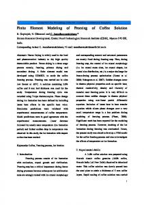
not important. Therefore, in this paper, we drop the discussion on this issue. Secondly, we consider the meshing of the simple absorbing boundary domain. It is unrealistic if we mesh 100 km boundary domain with the same meshing scheme as in the main computational domain where we need at least 4 elements per skin-depth. Fortunately, through extensive numerical tests, we have found out that in order to satisfy the accuracy that we aim (i.e. less than 1% error), we need only 20 elements through the thickness of the simple absorbing boundary domain and we increase the element size exponentially (e.g. distribution element ratio of 16). Note that since the physical media in relation to the CSEM method are conductive, this meshing of increasing exponentially element size would have the same effect as in the PML technique. To verify the proposed simple absorbing boundary domain, we solve a canonical example, shown in Fig. 1: seawater (3.2 Ωm) depth is 300 m; 0.25 Hz HED source is applied at 30 m above seabed and x=0; subsurface is homogeneous of 1 Ωm; inline electric field is recorded from x=0 to 10 km along the seabed. Note that the boundary at x=0 is a symmetric plane (i.e. modeling the half), and the size of the main computational domain is 10km×5km (red-dashed rectangular box in Fig. 1). The total number of the degrees of freedom (dof) is about 15,000. About 30% of this is in the simple absorbing boundary domain. Notice that the areas of the main computational domain and the simple absorbing boundary domain are 50km2 and 10000km2, respectively. The total computational time is less than 1 minute on a Pentium 4 machine (3.2GHz, 1GB RAM).
dashed rectangular box; the boundary at x=0 is a symmetric plane. Plots (a) and (b) in Fig. 2 show the results in terms of amplitude versus offset (AVO) curves, in comparison with an analytical solution [7]. It is clearly shown that the proposed simple absorbing boundary domain proposed in this study work very well, i.e. less than 1% relative error, except the near-offset response, as we expected and intended. We have done quite many numerical tests with changing the CSEM model parameters such as computational domain size, frequency, conductivity, introducing target layers or domains, and have found out that the proposed simple absorbing boundary domain works satisfactory.
(a) Absolute AVOs [V/m]
60 km thick for air/upper boundary domain
z in m
(b) Normalized AVOs Fig. 2. AVO curves, compared with analytical solution.
90 km wide for side boundary domain 10 km thick for lower boundary domain
4. On Advanced Boundary Conditions During the last decade, we have also experienced some other advanced boundary conditions or domains such as perfectly matched
x in m Fig. 1. Example FE model: 300 m sea-water; main computational domain is 10km×5km, red-
3
layer (PML) [1,6], boundary integral equation method (BIEM) [8], consistent transmitting boundary condition (CTBC) [5], impedance boundary condition, etc. Each of these domains and conditions has its own advantages and disadvantages. For example, the PML technique seems a most attractive one due to its name “perfectly …”. However, when applying it to the CSEM FE modeling, it is not trivial to determine the optimal PML parameters for the discrete numerical modeling. In addition, it may require highly-dense meshing. BIEM and CTBC should also be able to absorb the outgoing wave with high accuracy, when implemented properly. Nevertheless, these two suffer rather long computational time. In the near future, we are planned to extend this study and evaluate the simple boundary domain in comparison with the other advanced boundary domains or conditions.
adaptive finite-element algorithm, GEOPHYSICS, 72, WA51–WA62 (2007) 4. Mitsuhata, Y., 2-D electromagnetic modeling by finite-element method with a dipole source and topography, GEOPHYSICS, 65, 465–475 (2000) 5. Park, J., FEMLAB Simulation of LowFrequency EM waves for Subsurface Mapping in Geophysical Exploration, Invited Keynote lecture in FEMLAB Conference 2005, 13th of October, Oslo, Norway. 6. Park, J. and E. Kausel., A perfectly matched layer for the thin-layer method, 7th World Congress on Computational Mechanics, July 1622, 2006, Los Angeles, California, USA (2006). 7. Park, J., Test of new code CSEM1d_in_xy, NGI technical report, #20061263-1 (2006). 8. Park, J., 2.5D boundary integral equation solution for electromagnetic waves, NGI technical report, #20061460-2, (2007)
5. Conclusion
7. Acknowledgements
In this study, we proposed and briefly evaluated a simple absorbing boundary domain, which is efficient for the 2.5D finite element analysis in the context of the CSEM method. The simple absorbing boundary domain of this study is just an extension and continuation of the main computational domain. The simple absorbing boundary domain needs two main features to satisfy: 1) the domain size should be around 100 times skin-depth of the main computational domain; and 2) it needs about 20 quadratic elements through the thickness of the simple absorbing boundary domain with increasing exponentially size. In the near future, we are planned to extend this study and evaluate the simple boundary domain in comparison with the other advanced boundary domains or conditions.
We thank to StatoilHydro and Norwegian Geotechnical Institute for financial support for this study and permission to present.
6. References 1. Berenger, J., A perfectly matched layer for the absorption of electromagnetic waves, J. Comput. Phys. 114(2), 185-200. (1994). 2. Eidesmo, T., S. Ellingsrud, L. M. MacGregor, S. Constable, M. C. Sinha, S. E. Johansen, F. N. Kong, and H. Westerdahl, Sea Bed Logging (SBL), a new method for remote and direct identification of hydrocarbon filled layers in deepwater areas, First Break, 20, 144–152 (2002) 3. Li, Y. and K. Key, 2D marine controlledsource electromagnetic modeling: Part 1 - An
4