On Distributed Sampling of Smooth Non-Bandlimited Fields ∗
Animesh Kumar
[email protected]
Prakash Ishwar
[email protected]
Kannan Ramchandran
[email protected]
Department of Electrical Engineering and Computer Science University of California, Berkeley Berkeley, CA 94720
ABSTRACT Distributed sampling and reconstruction of a physical field using an array of sensors is a problem of considerable interest in environmental monitoring applications of sensor networks. Our recent work has focused on the sampling of bandlimited sensor fields. However, sensor fields are not perfectly bandlimited but typically have rapidly decaying spectra. In a classical sampling set-up it is possible to precede the A/D sampling operation with an appropriate analog anti-aliasing filter. However, in the case of sensor networks, this is infeasible since sampling must precede filtering. We show that even though the effects of aliasing on the reconstruction cannot be prevented due to the “filter-less” sampling constraint, they can be suitably controlled by oversampling and carefully reconstructing the field from the samples. We show using a dither-based scheme that it is possible to estimate non-bandlimited fields with a precision that depends on how fast the spectral content of the field decays. We develop a framework for analyzing non-bandlimited fields that lead to upper bounds on the maximum pointwise error for a spatial bit rate of R bits/meter. We present results for fields with exponentially decaying spectra as an illustration. In particular, we show that for fields f (t) with exponential tails; i.e., |F (ω)| √< παe−a|ω| , the √maximum pointwise error decays as c2 e−a1 R + c3 √1R e−2a1 R with spatial bit rate R bits/meter. Finally, we show that for fields with spectra that ³ have a ´finite second moment, the distortion decreases ¡ ¢2 as O N1 3 as the density of sensors, N , scales up to infinity . We show that if D is the targeted non-zero ³ distortion, ´ 1 then the required (finite) rate R scales as O √1D log D . Categories and Subject Descriptors: H.1.1 [Models and Principles]: Systems and information theory – Gen∗ This research was supported by NSF under grant CCR0219722 and DARPA under grant F30602-00-2-0538.
Permission to make digital or hard copies of all or part of this work for personal or classroom use is granted without fee provided that copies are not made or distributed for profit or commercial advantage and that copies bear this notice and the full citation on the first page. To copy otherwise, to republish, to post on servers or to redistribute to lists, requires prior specific permission and/or a fee. IPSN’04, April 26–27, 2004, Berkeley, California, USA. Copyright 2004 ACM 1-58113-846-6/04/0004 ...$5.00.
eral systems theory; C.2.4 [Computer-Communication Networks]: Distributed systems – Distributed applications. General Terms: Theory, Design. Keywords: Distributed sampling, sensor networks, nonbandlimited, aliasing, scaling laws, dither function, A/D conversion, oversampling.
1.
INTRODUCTION
With the inception of sensor networks, remote sensing of a physical field has become a topic of great interest [1, 2, 3]. Sensors are low precision devices with limited power resources and communication capability. An implementation using sensor networks is desirable if it uses local and limited communication and distributes the task at hand to the sensors in a uniform manner. For example, nearest neighbor communication will be desirable in a sensor network, compared to communication over a long range. The problem of distributed data acquisition in a bandlimited sensor field was recently addressed in [3]. However, in practice, the fields we intend to sample may not be bandlimited though the spectrum may be decaying sufficiently fast. This paper is accordingly motivated to look at the sampling of non bandlimited fields with rapidly decaying spectrum1 . A physical field varies spatio-temporally, i.e., varies over space and evolves with time. We will focus on the sampling of a one dimensional spatial field for one particular temporal snapshot2 . For simplicity, we will deal with one dimensional fields. The classical approach of dealing with non-bandlimited fields is to prefilter by the so-called antialiasing filter [5] at a sufficiently high bandwidth and then sample the resulting bandlimited field. This approach cannot be implemented in a distributed manner since the available physical field cannot be filtered in spatial domain before quantization. However, it will be shown that even in the absence of prefiltering, at sufficiently high sampling rates the aliasing error decreases fast enough to enable a good quality reconstruction of the physical field using poor precision sensors. While it is somewhat intuitive that increasing the sampling rate will reduce the aliasing error, we provide concrete guidelines for the selection of appropriate sampling rates and 1 Such fields encompass many classes of physical fields, such as temperature and pressure. 2 If smooth models for temporal models are assumed, temporal interpolation can be performed using a variety of methods[4]
sensor precision based on the knowledge of the spectral envelope. The proposed method deals with decaying spectral tails by oversampling the field of interest at a sufficiently high rate so that the aliasing error becomes comparable to the quantization error. The aliasing error need not (and cannot) be made zero since the error due to quantization is inevitable. Hence, making these errors comparable is the guiding principle. Most current sensor network scenarios may be broadly categorized into (a) networks for monitoring that are eventdriven and delay-sensitive; and (b) networks for collecting new information that are data-driven. This work belongs exclusively to the latter category, which may be further broken down, at an information processing level, into two broad functional tasks: (i) data-acquisition or sampling of the sensor field; and (ii) data transport, where the acquired data is disseminated across the network to a data-collecting unit (for example). We address the former issue in this work, and data transport aspects, though important, are not discussed in this work.
fP N (t) =
P
l f (lT )φT (t − lT )
5T 6T 0
T
2T 3T 4T
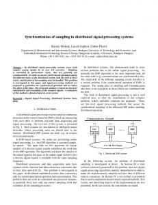
Figure 1: Pseudo-Nyquist style sampling set-up: High precision sensors are distributed uniformly along a straight line with period T called the pseudo-Nyquist period. The observed field values are quantized and the quantized samples are used to reconstruction a bandlimited approximation to the original field. The choice of T depends on the precision of sensors (see Section 3). The functions φT (t − lT ), l ∈ Z are the bandlimited interpolating functions.
We illustrate a pseudo-Nyquist (PN) style sampling setup in Figure 1. High precision nodes are deployed uniformly along a straight line at a sampling rate T referred to as the pseudo-Nyquist rate, and the field values are recorded and quantized, using a uniform scalar quantizer, up to a precision of k-bits3 . These high precision samples are interpolated using stable bandlimited kernels pretending that the field is bandlimited to the sampling rate (hence the term pseudo). Since aliasing error and quantization error are simultaneously present in the reconstruction, T will be chosen to balance the two errors. We will use this scheme as a performance benchmark for our oversampling methods using poor precision sensors which we describe next. We illustrate the data acquisition model in Figure 2. We assume that 1-bit sensor nodes are densely and uniformly distributed on a straight line and there is a central data collector, which in every snapshot, receives the data from only one sensor in an interval of length T . Since the cost of 3 These ideas will be made mathematically precise in the later sections.
Data Collector
log M bit message to the data collector
2−bit local messages
M sensors every T
T
T
Figure 2: 1-bit sensors are uniformly placed on a straight line. The sensors We assume propagate 2-bit messages locally to determine representatives (filled-circles) in each T -interval. The selected representatives for a particular snapshot communicate their address to the central data collector. The choice of T for a sensor density M is determined by the pseudo Nyquist setup with sensors having a resolution of log M bits.
communication in the context of sensor networks is higher for longer distances, our results will be in terms of the spatial bitrate, R, to the data collector. We will however show that the local communication cost per unit length is fixed. In this work, we consider deterministic fields f (t) with rapidly decaying spectrum |F (ω)|. We will focus on the maximum pointwise error between the field and its reconstruction as the distortion criterion, i.e., D := ||f − frec ||∞ , where frec (t) is the reconstruction of the field at the central data collector. We will describe an algorithm for computing the error-rat characteristics based on the spectral decay of the field. Specializing the algorithm to fields with an exponentially decaying spectrum provides an upper bound √ on the maximum pointwise error: c1 e−a1 R for the pseudoNyquist (PN) set up. For the 1-bit oversampling setup (see √ √ Figure 2), the error behaves as c2 e−a1 R + c3 √1R e−2a1 R . We shall return to discuss the order asymmetry of the results later, but note that the distortion still goes to zero as the rate goes to infinity. Thus for a finite non-zero distortion D, the required rate R is finite and there is no need to scale the network beyond a finite limit determined by D. Unlike prior work [1, 2], in our case D → 0 as the sensor density N → ∞. In our previous work [3], we showed that for an amplitude limited and bandlimited field, if we use k-bits to describe the sample in every Nyquist interval of length λ1 , ³then the ´ max¡ −k ¢ −R imum pointwise error decays as O 2 = O 2 λ , where R = kλ is the bitrate in bits per meter. Moreover, this exponential accuracy can be achieved with arbitrary precision sensors by trading off sensor density with sensor precision. For example, if b-bit sensors are used, then 2k−b+1 sensors are needed in every interval to obtain an accuracy ¡ Nyquist ¢ of the order of O 2−k . This phenomenon was termed as the bit-conservation principle. A similar tradeoff with an exponential reconstruction accuracy can also be obtained for a uniformly bounded wide sense stationary process X, with bandlimited and finite energy autocorrelation function RX (t)[6]. However, the assumption of a bandlimited field is too restrictive. Hence, in this work we address the problem of sampling a smooth non-bandlimited field. In what follows, we show that it is still possible to sample the physical field
in a distributed manner, however, the error-rate profile is not the same as for the bandlimited case. We also show an achievable asymptotic density-precision tradeoff law. Using this law, sensor density can be traded off with sensor precision, for a fixed error and rate. The main contributions of this paper are as follows: 1. We rigorously characterize the effect of oversampling and quantization on a smooth non-bandlimited field. In particular we show that the absence of an antialiasing filter only affects the constant term in the error. 2. We show how the sampling can be done in a distributed setting using many 1-bit sensors while achieving a similar asymptotic error-rate characteristic as a scheme with high precision nodes. For high rates, we show the existence of a tradeoff between precision of sensor and average oversampling density. 3. We uncover an important “information scaling law” that establishes how information “grows” as a function of number of sensors, and show that the per-node per-snapshot³information requirement goes to zero: for ´ 2 example, O logN N for non-bandlimited fields with exponentially decaying spectral envelope, where N is the sensor density in sensors per meter. The precise utility of this scaling law depends on the underlying routing protocol and transport model used to move this information from the sensors to the data-collector. Nonetheless, the fact that the per-node information needs to go zero is comforting and counters the “pessimistic” scaling law results for ad-hoc networks by Gupta and Kumar which (for a specific point-to-point transport model) establish that the per-node transport capabilities go to zero as the network scales[7]. Our results show that even in this regime, it is possible to do “useful” work in sensor networks, i.e., reconstruct a field with arbitrary reconstruction accuracy. For the rest of the paper, f (t) denotes a deterministic, differentiable, and finite energy field with arbitrary spectrum and amplitude uniformly bounded by 1, i.e. |f (t)| < 1. We denote the pseudo-Nyquist (PN) interval by T and assume Rthat we have M sensors for every R PN interval. We will use F (ω)dω, i.e., dω will be F (ω) to denote the integral A A understood in the integral. The rest of the paper is organized as follows. In Section 2 we first present the applications of our results to sensor networks. In Section 3 we present the PN sampling set-up and its analysis. In Section 4 we show how the field can be sampled in a distributed setting and compare the results with the PN sampling framework. In Section 5 we present the achievable density-precision tradeoff law for high rates R, and finally we conclude in Section 7.
2.
APPLICATION TO SENSOR NETWORKS
We would like to emphasize that the target application scenario of this work is one where there is some information available about the underlying field being sensed. In particular, it is assumed that the bounding envelopes for the spectral characteristics and the dynamic range of the field is known to the network architects. This theory does not apply
to the scenario where nothing is known about the field. The purpose of this section is to illustrate, at a high level, the implications of the theory developed in the later sections in the context of sensor networks. The discussion will be based on 1-bit sensor nodes, however, the extension to the general case of b-bit sensors is analogous. In what follows, we focus only on the information density and acquisition aspects of the field. The transport aspect is important, but is not addressed here. We assume that M sensors of 1-bit precision are deployed in every interval of length T , see Figure 2. The length T depends on the spectral decay of the field and the number of sensors M . Henceforth, every T -interval will refer to the intervals of the form [lT, (l + 1)T ), l ∈ Z. The sensors pass 2-bit local messages4 , say from left to right, to select one representative within each T interval (shaded circles in Figure 2). The local messages are such that: (i) only one representative is selected within each T interval and (ii) the messages start at the beginning of the T -interval and “ripple” in one direction till the end of that T interval. These selected representatives communicate their addresses within each T interval (requiring log M bits) to the central data-collector5 . Thus RT = logTM is the bitrate to the central collector. Why is such a scheme useful? How does the distortion behaves with the rate? These and other issues will be answered in the technical sections where we show that this scheme, with suitable local messages, has a distortion that is comparable to the centralized classical setup up to constants. In every T -interval, the sensor which is the representative for a particular time snapshot records a ‘1’, while others record a ‘0’. We now discuss how this information grows on a per-snapshot basis, and how this information can be coded over multiple time snapshots using the source coding ideas of information theory[8]. Growth of information To understand how the sensor data-rate grows with M and T one needs to specify, at some level, a temporal model for the evolution of the field. For a fixed non-zero distortion, the temporal sequence of the ‘0-1’ pattern in every T -interval contains all the information pertaining to the field. Suppose that the sensors within each T -interval could collaborate without penalty to jointly encode the 0-1 pattern over many temporal snapshots. By design, there is exactly one sensor per T -interval per snapshot that will record the value 1. Hence, the M -length vector of zeros and ones in any T -interval can take only M distinct values in each snapshot. Irrespective of the exact nature of the temporal evolution, in the worst case, no more than RT = log2 (M ) bits per snapshot per T -interval are needed to encode the M -length vectors of the 0-1 pattern. Suppose that each sensor has a uniform chance of beaming a representative averaged over a long time window of snapshots. Then the rate in bits per unit time needed for sensors to en1 code their ‘0-1’ information is Rsensor ≈ M log2 M . In the sequel it will be shown that, for fields with finite absolute second moment in the spectral domain, a target non-zero distortion can be achieved by finite M and a non-zero T . This is quite unlike the results in [2] and [1] where the dis4 What these messages are will be clear after reading the later sections; as mentioned, this section describes the implications of the theory developed later in the context of sensor network. 5 This need not be done in real time. The processed data can be aggregated over time and sent with the address information as a header.
tortion does not go to zero even as the number of nodes per unit length, N , goes to infinity. Equivalently, for a fixed D > 0, the number of 1-bit sensors per T -interval is finite. For example, for a field with exponentially decaying ³ ´ ¡1¢ ¡ ¢ 1 spectrum, M = O D , T = O | log D| , R = O | log D|2 , ´ ³ D| and N = O (M log M ) = O | log . For fields with a fiD nite second moment in the spectral domain we obtain ³q ³¡ ¢ 2 ´ ´ ³ ´D = −3 1 3 1 1 2 ,R = O O N log D , and N = O D for D high rates or equivalently for small distortions. Local inter-sensor communication cost: The sensors ripple 2-bit messages in every T -interval (b + 1-bit messages for the general case with b-bit sensors). The 2-bit message T ripples through every T -interval (resp. 2b−1 , and hence the local communication cost in bit meter is 2T (resp. (b+1)T ). 2b−1 = 2 The local communication cost density in bits is 2T T (resp. 2b+1 b−1 ). Each 1-bit precision sensor transmits 2-bits to T its right neighbor over a distance of M . Hence, the local 2T sensor communication cost is M bit-meters for each sensor (resp. (b+1)T ). M Sensor distribution: In the sequel we shall derive an achievable density-precision tradeoff law: for a target distortion D, the data rate to the data collector is independent of the precision of the device used, and the precision of the device is traded off with its density. For instance, in any M T -interval, M sensors of 1-bit precision or Mb := 2b−1 sensors of b-bit precision, or 1 sensor of log M bits precision, all result in similar distortion. As we increase the sensor precision Mb , the number of b-bit sensors every T -interval decreases exponentially as b increases while maintaining the same asymptotic error decay profile. h Sensors need to´ be placed only in intervals of the −1)T form lT , lT + (MbM instead of [lT, (L + 1)T ], where T is fixed according to the the spectral decay of the field and the target distortion. This leaves regions over which there is no need to deploy the sensors at all. Since the scheme naturally allows “inactive” regions in oversampling, we can have bunched irregular sampling using sensors. This allows for design flexibility in sensor deployment. For example, in rugged terrain or in the presence of occluding obstacles, one would need to use higher precision sensors. Where sensors can be deployed in large numbers it is sufficient to use cheap 1-bit sensors. Robustness: The proposed oversampling method also offers robustness to node failures in terms of a graceful degradation of reconstruction error. The reconstruction error depends on the inter-node spacing in the sensor network. For example, if every alternate device fails in a network, the T inter-sensor spacing increases from M to 2T . The effect of M such a failure will depend on the behavior of the spectral decay, however, the degradation will not be abrupt. However, if the field was sampled with only high precision sensors, a node failure is equivalent to the loss of all the single-bit sensors in a T -interval.
3.
PSEUDO-NYQUIST SAMPLING USING HIGH PRECISION SENSORS
Consider a finite energy bandlimited function u(t) bandlimited in [−π, π], then for any fixed¡ λ > 1, ¢ there exists a set of orthogonal basis functions {φλ t − λl }, bandlimited
in [−λπ, λπ] such that[9, 3] µ ¶ X µl¶ l φλ t − , and u(t) = u λ λ l∈Z ¶¯ X ¯¯ µ ¯ ¯φλ t − l ¯ < C < ∞, sup ¯ λ ¯ t∈R
(1) (2)
l∈Z
where the equality in (1) holds absolutely, pointwise and uniformly. Stable reconstruction for £ a finite ¤ energy bandlimited function uT (t), bandlimited to − Tπ , Tπ , can be derived from (1) by scaling the function φλ (t) appropriately, µ ¶ µ ¶ X lT lT uT (t) = uT φT t − , (3) λ λ l∈Z
¡ ¢ where, φT (t) := φλ Tt . From (2) it can be deduced that ¶¯ X ¯¯ µ ¯ ¯φT t − lT ¯ < C independent of T. sup (4) ¯ λ ¯ t∈R l∈Z
We now describe the pseudo-Nyquist (PN) sampling setup. Choose T sufficiently small, so that a significant portion of the spectrum F (ω) is contained within W := Tπ . Then the samples of the field are quantized using a uniform kbit scalar quantizer Qk (.) on the domain [−1, 1] [10]. As a result, for any t0 ∈ R, since |f (t0 )| < 1, |Qk (f (t0 ))−f (t0 )| < 2−k . The projection £ ¤of f (t) onto the space of bandlimited functions on − Tπ , Tπ is given by fp (t) ←→ F (ω): ³ π´ , Fp (ω) = F (ω)1 |ω| < T where 1(A) is the indicator function function of the set A. We suppress the dependence of fp (t) on T to keep the notation simple. T will be chosen to satisfy distortion constraints. The PN scheme is to pretend that the samples are coming from a Tπ -bandlimited field, and perform a stable on the samples. Let ¡ ¢bandlimited ¡ ¡ lT reconstruction ¢¢ fbP N lT := Q f be the quantized field values (resk λ λ olution of k-bits). Note that, the samples are collected at every Tλ interval, slightly smaller than T (λ > 1 can be thought of as a fixed oversampling factor for stability in bandlimited reconstruction). Let the Tλ -spacing reconstruc¡ ¢ ¡ ¢ P tions be defined as fP N (t) := l∈Z f lT φT t − lT and λ λ ¡ lT ¢ ¡ ¢ P fbP N (t) := l∈Z fbP N λ φT t − lT . Then, the maximum λ pointwise error is bounded by the following proposition: Proposition 3.1. For the pseudo-Nyquist sampling setup, the maximum pointwise reconstruction error is upper bounded as |f (t) − fbP N (t)|
W |F (ω)| for ω>W |F (ω)|dω, i.e., dω is understood; we will follow this convention throughout. The proposition shows that the maximum pointwise error for the PN style sampling is a linear combination of per sample quantization error and the aliasing error. From (6), we see that the knowledge of the spectral envelope will help avail the analysis of maximum pointwise error. From (5), we see that the aliasing error need not be made arbitrarily small,
Fp (w)
F(w)
ω
Wω
−W
(a)
(c) aliased copies of F(w)
F PN (w)
l
W ω
−W
(b)
f (t) = Σ f(lT) φT (t−lT) PN
FD (w)
5T 6T 0
T
2T 3T 4T
W
−W
(d)
ω
(e)
Figure 3: (a) Spectrum of f (t). (b) Fp (ω) is the lowpass projection of f (t) on [−W, W ]. Note that F (ω) and Fp (ω) differ only outside the interval [−W, W ]. (c) This depicts a typical bandlimited interpolation of the field from non-uniform samples. The interpolation has spectral content only in [−W, W ] and is zero outside. (d) & (e) We show the PN reconstruction obtained from un-quantized samples f (lT ) and its spectrum. The field is sampled at pseudo-Nyquist rate T and then it is reconstructed with bandlimited interpolating kernels. As a result, the field aliases in spectral domain (see (e)). FP N (ω) ≡ FP N (ω)1 (ω ∈ [−W, W ]) is limited to a bandwidth of [−W, W ].
but only until it becomes comparable with the quantization error. We will use this idea while deriving rate dependent upper bounds on reconstruction error. Example:
SAMPLING WITH 1-BIT PRECISION SENSORS Following similar ideas as in [9, 3], we will h assume ithat (i−1)T iT , λ . λ
there are M one-bit sensors in every interval
i∈Z
Since the field is assumed to have a dynamic range [−1, 1], therefore, a dither function dT (t) with the following properties a zero crossing in every interval of the form h will enforce i (i−1)T iT , : λ λ
|F(w)|
f(t)
4.
− a|w|
α πe
i∈Z
t
W0
−W0
w
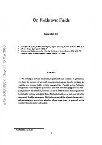
Figure 4: Example of a non-bandlimited field with an exponentially decaying spectral envelope beyond a bandwidth of W0 .
Let f1 (t) be a finite energy differentiable field with spectrum F1 (ω) decaying faster than απe−a|ω| for |ω| > W0 , i.e. |F (ω)| < απe−a|ω| , |ω| > W0 . For T < Wπ0 and using (6), Z α α πa ||f1 − f1p ||∞ < α e−aω = e−aW = e− T .(7) a a ω>W Putting the result of (7) in (5), we get |f1 (t) − fb1P N (t)| < A1 e
−πa T
+ C2−k . −πa
−πa T
= (A1 + C)e−
√
√ πaλ log 2 R
• dT (t) is smooth, i.e., it is differentiable in R and supt∈R |d0T (t)| < ∆ , for some finite ∆. T ¡ λπt ¢ For example, γ cos T , γ > 1 is a valid dither function. The third property of the dither function implies that dT (t) is continuous. We assumed f (t) to be differentiable (hence continuous) ⇒ the dithered field f (t) + dT (t) is continuous. This together with the first two properties of the dither function guarantees (by the intermediate value theorem for continuous functions [11]) that ³ f (t) +´dT (t) will have a zero-crossing in every interval
As a very simple strategy, put 2−k = e T , then the spatial = T 2πaλ . The maximum bitrate R is given by R = kλ T log 2 pointwise error D is given by D = (A1 + C)e
¯ ¡ ¢¯ ¯ = γ > 1 for all i ∈ Z. • ¯dT iT λ ´´ ³ ³ ¡ ¡ ¢¢ • sgn dT iT for all i ∈ Z. = −sgn dT (i−1)T λ λ
.
(8)
The main point to note is the exponentially decaying dis√ tortion in R, and we will show that the 1-bit dithered distributed sampling scheme also attains similar asymptotic characteristics (the constant changes but the exponent remains the same). Also, as argued earlier, the idea is to make the two errors, quantization and aliasing, comparable. We will return to this example in the next section in the context of distributed sampling using low precision sensors.
lT λ
,
(l+1)T λ
. M one-
bit A/D converters are placed uniformly in every T -length interval to record the sign of the dithered field f (t) + dT (t), i.e., sensors are placed at the locations {mτM }m∈Z where /λ) τM := (TM is the uniform oversampling period. To avoid clutter, we shall henceforth drop the subscript M in τM . index ¢for which Let ml ∈ ¡ {0, . . . , M ¢ − 1} be the¡ smallest lT [f + dT ] lT + m τ and [f + d ] + (m + 1)τ have opT l l λ λ i h lT (l+1)T . It follows from the intermediposite signs in λ , λ ate value theorem that f (zl ) +¢dT (zl ) = 0 at some point ¡ zl ∈ lT + ml τ, lT + (ml + 1)τ , i.e., zl is the location of λ λ i h . , (l+1)T the first zero-crossing of [f + dT ] in the interval lT λ λ ¡ ¢ lT 1 Let tl = λ + ml + 2 τ, l ∈ Z. The locations {tl } are
nonuniform, and hence we need a sampling theory result which provides stable bandlimited interpolating functions for reconstruction from nonuniform samples. The following result will be used in the sequel. Fact 4.1. [9] Let λ > 1 be fixed. If {tl }l∈Z is a set of sampling positions¯ such that δ := inf j,l∈Z,j6=l |tj − tl | > ¯ 0 and κ := supl∈Z ¯tl − λl ¯ < ∞ then there exist absolutely integrable interpolating functions ψl (t) such that for any finite-energy function u(t) with spectral support contained in [−π, π], u(t) = lim
L X
L−→∞
" C 0 := sup t∈R
u(tl )ψl (t − tl ),
l=−L
X
(9)
(10)
l∈Z
with the convergence holding pointwise (and in L2 ), absolutely, and uniformly on all compact subsets of R. For a bandwidth of W := Tπ , let the interpolation functions be ψT,l (t − tl ). This theorem holds for arbitrary band0 width functions but the theorem does not £P tells how C in ¤ (10) will vary will T . Let C 0 (T ) = supt∈R |ψ (t − t l l )| , l∈Z then a simple scaling argument shows that there exists a constant C 0 independent of T such that C 0 (T ) = C 0 : Lemma 4.1. For the sequence that inf l,m∈Z,l6=m ¯ {tl } such ¯ ¯ < κT , δ and κ inde|tl − tm | > δT > 0 and supl∈Z ¯tl − lT λ pendent ofP T , the pointwise absolute sum of the interpolating functions l |ψT,l (t − tl )| is bounded by C 0 , independent of T , i.e., X sup |ψT,l (t − tl )| < C 0 . (11) t∈R
Proposition 4.1. For the 1-bit dithered sampling set-up, the maximum pointwise reconstruction error is upper bounded as 0
|f (t) − fbD1 (t)|
0,¯ κ < ¯ ∞ ¯< such that inf l,m∈Z,l6=m |tl − tm | > δT and supl∈Z ¯t − lT λ κT for the 1-bit dither based sampling scheme. Since one T sample is collected ¯in every therefore, it is easy ¯ λ -interval, lT ¯ ¯ to see that supl∈Z t − λ < Tλ = κT , with κ = λ1 . For inf l,m∈Z,l6=m |tl − tm | an obvious lowerbound is τ since the {tl }l∈Z cannot get closer than τ /2 to the endpoints of the Nyquist-interval by design. This lowerbound depends on τ . However, since |d(t) + f (t)| ≥ |d(t)| − |f (t)| ≥ |d(t)| − 1, a zero crossing cannot take place unless the amplitude of d falls below unity. Since |d( lT )| = γ > 1, the closest that a λ ¡ ¢ zero-crossing can get to a Nyquist-point is T γ−1 . Hence, ∆ ´ ³ − τ . Together with the inf l,m∈Z,l6=m |tl − tm | ≥ 2T (γ−1) ∆ earlier obvious lowerbound inf l,m∈Z,l6=m¡ |tl −¢ tm | ≥ τ , this means that inf l,m∈Z,l6=m |tl − tm | ≥ T γ−1 = δT , where ∆ δ = γ−1 . ∆ For a fair comparison with the PN case, we will assume that there are M = 2k sensors in every interval T . This will make the spatial bitrate the same as in the PN case, i.e., k-bits every Tλ interval. The inter-sensor spacing is τ = MTλ . Since tl is close to zl , the zero-crossing location, the field value at tl is approximated by fbD1 (tl ) = −dT (tl ).
||f − fp ||∞ ||f 0 ||∞
||f ||∞ ) 000 C 00 ||f − fp ||∞ + (∆+T M C , (12) R 1 < |F (ω)|, and, π ω>W R < Tπ [1 + ||f − fp ||∞ ] + π1 ω>Wω|F (ω)|,(13)
where, C 00 = (1 + C 0 ) and C 000 =
C0 . 2λ
Proof. See Appendix 8.3 This proposition shows that the error between the field and the dither based reconstruction consists of two terms: the first term is due to aliasing errors and the second due to the uncertainty in the location of the zero-crossing. The decaying spectral envelope provides an upper bound on the maximum slope of field in terms of T . We illustrate the use of the inequalities in (12) and (13) in the context of the example in the previous section: Example (contd.): Consider f1 (t) with spectrum F1 (ω) < παe−a|ω| for |ω| > W0 , for some W0R. ||f − fp ||∞ is bounded as in (7). We can upper bound ω>W ω|F (ω)| using the exponential παe−a|ω| instead of |F (ω)| inside the integral. The result is Z α(aW + 1) −aW 1 e , ω|F (ω)| < π ω>W a2 Z α(a Tπ + 1) −πa 1 e T . (14) ⇒ ω|F (ω)| < π ω>W a2 Putting (13) and (14) in (12) we get, |f (t) − fbD1 (t)|
W1 , Z ³ W ω´ 1+ |F (ω)| < J (18) π ω>W W for some constant6 J. Then for all T ≤ T1 := Wπ1 there exists a dither function d©T,b (t) such that f ¡(t)+dT,b (t) ¢ªwill cross 1 1 a level in the set Λ = 0, ± 2b−1 , . . . , ± 1 − 2b−1 in every £ ¡ ¢ ¤ interval of the form [Al , Bl ] := lT , lT + 2k−b+1 − 1 τ ⊂ λ λ h i lT (l+1)T , λ . λ Proof. See Appendix 8.4 This theorem can be interpreted as follows: the function f (t) can be decomposed into a bandlimited projection term fp (t), and a highpass term with decaying spectral content. fp (t) has a uniformly bounded slope. Since the spectral content of the high-pass term reduces as the rate is increased (T is decreased), after some threshold, it will be small enough so that it does not affect the slope of the fp (t) by a large amount. Thus, the uniform (bandwidth dependent) bound on the slope can be used to design an appropriate dither function and enforce a level crossing in every PN interval. For high rates or T < T1 of theorem 5.1 (the rate is dependent on the field) it is straightforward to generalize the 1-bit scheme to a b -bit dithered scheme as follows: £ • For every l ∈ Z, place sensors in the interval lT , lT + λ λ ¡ k−b+1 ¢ ¤ . Choose 2 − 1 τ , at every τ starting from lT λ a dither function dT,b (t) as in (25). • Record the field value f (t) and compare it with the local dither value dT,b (t). Record the level of f (t) + £ ¤ dT,b (t) at the locations lT , lT + (i − 1)τ , i = 1, 2, . . . , λ λ 2k−b+1 . This requires Mb = 2k−b+1 sensors in every T interval. • Starting from the node at lT the sensors communiλ cate the observed level of f (t) + dT,b (t) to their nearest right neighbor. When the receiving node observes a level change, it communicates the level and location to the central data collector (alternatively, this information can be stored over many snapshots, compressed and communicated later). If the level crossing has already been observed, the sensors pass a 1-bit flag to the right neighbors to indicate that a level crossing has been observed. This local communication requires at bT most CL = 2k−b+1 bit-meter every T . Hence the lob cal communication cost density is CTL = 2k−b+1 (cost density is bounded).
π ||uT ||∞ T
We now show that a bandwidth dependent upper bound exists for non-bandlimited fields Rfor T small enough. If we R assume that ω>W ω|F (ω)| and ω>W |F (ω)| decay to zero with increasing W , then from (13) it is clear that the bound on the slope of f (t) will get close to Tπ = W ¡ . For instance, the exponentially decaying spectrum, W · ||f − fp ||∞ + π1 ´ R ω|F (ω)| → 0 as W → ∞. Thus, eventually the slope ω>W will be close to W and hence
the slope of the field. Formally, we can state the following:
will be a uniform bound on
• The data collector has non-uniform ¡ ¢ samples of the field 1 at the locations tl = lT + m + τ as fbDb (tl ) = (ql − l λ 2 dT,b (tl )), where ql ∈ Λ is the level that was crossed. • The field is reconstructed according to X fbD (t) = fbD (tl )ψT,l (t − tl ). b
b
l∈Z 6
We will show later that fields with a finite second moment in spectral domain satisfy this property. Hence, this assumption is not very restrictive.
Then, using the uniform bound (J + 1)W on ||f 0 ||∞ and (12), the following holds: D0 M < C 00 ||f − fp ||∞ + D0 2−k ´ ³ ³ 2k−b+1 where ∆b = ∆ 1 + π(J+1) W W π ω>W W ω3 3A < → 0 as W → ∞ 2πW Note that the tradeoff is shown for high rate or high sensor density. In other cases (i.e. low rates), the tradeoff remains an open problem. We can summarize the achievable asymptotic density-precision tradeoff law as follows: Achievable asymptotic density-precision tradeoff law: Let k be the number of bits available per Tλ -interval. For each 1 ≤ b < k there exists a dither-based sampling scheme with not more than 2k−b+1 , b-bit sensors per Tλ -interval achieving same order worst-case pointwise reconstruction accuracy as the pseudo-Nyquist setup. Example: Error-rate characteristics of fields with a finite second absolute spectral moment: As noted earlier |F2 (ω)| < A , ω > W0 , and therefore, for W > W0 ω3 Z Z A A and |F (ω)| < ω|F (ω)| < 2 2W W ω>W ω>W A Therefore, from (5) |f3 (t) − fb3P N (t)| < (1 + C) 2πW 2 + −k 0 2 −k 0 A C2 = A4 T + C2 , where A4 = (1 + C) 2π3 . Choose T 2 = 2−k , gives R = λ(−2 Tlog2 T ) and D = (A04 + C)T 2 . Eliminating T we can arrive at the following µ 0 ¶ r 0 (A4 + C) A4 + C R = λ log2 · . D D
Note that A04 > 0, C > 1 and D < 1 so that R > 0. Also, for a finite D, the required rate R is finite. For 1-bit dithered scheme, from (12) and (13) D = A5 T 2 + 0 0 +1) , B5 = C (π+∆) (B5 + A05 T 2 )2−k where A5 = A(C and 2λ 2π 3 µ
A05
=
AC 0 . π2 λ
Choose 2
−k
=
and R is finite for a fixed non zero target³q distortion D.´ ¡1¢ 1 log D for Asymptotically R is of the order of O D both the PN and the dithered sampling set-up.
T2 . B5 +A05 T 2
Then R =
λ log
0 B5 T2
+A05
´
We summarize the main points made in this paper as follows: • For non-bandlimited fields, the error-rate characteristic is spectrum-dependent. • The total error can be decomposed as the sum of the aliasing and the quantization errors. These errors can be controlled by a suitable choice of the sensor density. • There is considerable flexibility for trading off the sensor density for the sensor precision while maintaining almost the same high-rate achievable error-rate behavior. • For a non-zero target distortion, the acquisition phase for amplitude limited smooth non-bandlimited fields requires a finite spatial bitrate to the central data collector.
7. CONCLUSIONS AND FUTURE WORK We addressed the problem of deterministic oversampling and reconstruction of smooth non-bandlimited fields and showed that the maximum pointwise error decreases to zero as the bitrate goes to infinity. This work extends the scope of the distributed sampling framework to beyond the regime of bandlimited fields where prefiltering with an anti-aliasing filter is infeasible. We showed that even though the aliasing effects cannot be prevented, due to the filter-less sampling constraint, it can be controlled by suitable oversampling and interpolation. We showed how the distributed sampling framework can be applied to sensor networks, with distortion going to zero as the number of sensors in the network scales to infinity. We also showed the existence of an achievable high-rate trade-off law between sensor precision and sensor density. Ongoing work includes further extensions to non-bandlimited, wide-sense-stationary processes, and to fields having a finite rate of innovation [15].
8. APPENDIX 8.1
Proof. |f (t) − fbP N (t)| (a)
W where (a) follows by the conjugate symmetry of the Fourier transform of real functions.
8.2
Independence of C 0 from T
Proof. Let {sl }l∈Z be¯ a sequence with inf l,m∈Z,l6=m |sl − ¯ sm | = δ > 0 and supl∈Z ¯sl − λl ¯ = κ < ∞, which forms a stable sampling set for functions with spectral support on [−π, π]. Let ψl (t − sl ), l ∈ Z be the interpolating functions for the sampling set {sl }l∈Z for reconstructing a function u(t) with spectral support P in [−π, π]. Then using Fact 4.1, we can write u(t) = l u(sl )ψl (t − sl ), where the convergence holds uniformly, pointwise, absolutely, and in L2 P sense. Also, supt l∈Z |ψl (t − sl )| = C 0 < ∞ and the constant C 0 depends only on δ and κ. £ Now,¤ consider a function uT (t) with spectral support in − Tπ , Tπ . The scaled function v(t) := uT (tT ) will have spectral support in [−π, π]. Hence, v(t) =
X
v(sl )ψl (t − sl ).
8.3
1-bit dithered sampling and reconstruction error
Proof. |f (t) − fbD1 (t)| (a)