Jul 28, 2015 - Email: {s_tatsumi@, hariyama@, miura@aoki., ito@aoki., aoki@}ecei.tohoku.ac.jp. Abstractâ This paper proposes a Field Programmable Gate.
90
Int'l Conf. Par. and Dist. Proc. Tech. and Appl. | PDPTA'15 |
OpenCL-Based Design of an FPGA Accelerator for Phase-Based Correspondence Matching Shunsuke Tatsumi, Masanori Hariyama, Mamoru Miura, Koichi Ito, Takafumi Aoki Graduate School of Information Sciences, Tohoku University Aoba 6-6-05, Aramaki Aza, Aoba, Sendai, Miyagi, 980-8579, Japan Email: {s_tatsumi@, hariyama@, miura@aoki., ito@aoki., aoki@}ecei.tohoku.ac.jp Abstract— This paper proposes a Field Programmable Gate Array (FPGA) implementation of the stereo correspondence matching using Phase-Only Correlation (POC). The use of high-accuracy stereo correspondence matching based on POC makes it possible to measure accurate 3D shape of an object using stereo vision. The drawback of the POC-based approach is its high computational cost. To address this problem, we propose an FPGA implementation of the POCbased correspondence matching. To design the accelerator efficiently, the OpenCL-based design tool is used which allows us to reuse the existing code for Graphics Processing Units (GPUs). Although reusing the OpenCL code for GPUs, optimizing the code for FPGAs is a tough problem because the architectures of GPUs and FPGAs are completely different. The major contribution of this paper is to address the optimization technologies of an OpenCL-based FPGA accelerator. The implementation results demonstrate that the FPGA implementation has the almost same speed as well as much higher energy efficiency. Keywords: stereo vision, phase-only correlation, real-time 3D measurement, OpenCL, FPGA.
1. Introduction Image correspondence is an important fundamental task in a variety of image processing [1] such applications as stereo vision, motion analysis, biometrics, etc. Especially for stereo-vision 3D measurement, high-accuracy and dense image correspondence is essential. For the purpose of accurate and dense 3D measurement, we have proposed a stereo correspondence algorithm using Phase-Only Correlation (POC) [2]. POC is an image matching technique using the phase components in Discrete Fourier Transforms (DFTs) of given images. We have also developed a passive 3D measurement system using stereo vision whose accuracy is comparable with the active 3D measurement system. However, the POC-based correspondence matching is limited due to the high computational cost, since POC is based on Fourier transform. Also, the computational cost of the POC-based correspondence matching is significantly increased when measuring the dense 3D shape of an object. This results in the large computing time on CPU implementation even though the multi-thread technique is
used. Another problem of the CPU implementation is its large power consumption. To solve this problem, Graphics Processing Unit (GPU) implementation of POC has been proposed [3] where the OpenCL language is used for design. The GPU implementation is up-to 5 times faster than a CPU implementation. However, its large-power problem is still remaining. This paper presents a Field Programmable Gate Array (FPGA) implementation of the POC-based correspondence matching, which can achieve high-speed and low-power consumption. To design the FPGA-based accelerator efficiently, the OpenCL-based design tool is used which allows us to reuse the existing code for GPUs. OpenCL is a framework supporting parallel programming in heterogeneous computational environments such as multi-core CPUs and GPUs. It provides efficient parallel computing using both task-based and data-based parallelism [4]. Recently, Altera corp. starts to provide the OpenCL design environment for FPGAs [5]. Although reusing the OpenCL code for GPUs, optimizing the code for FPGAs are a tough problem because the architectures of GPUs and FPGAs are completely different. We describe some optimization techniques such as pipelining and data reusing suitable for OpenCL-based design for FPGAs. The implementation result demonstrate that the FPGA implementation has the almost same speed as well as much higher energy efficiency. The use of FPGAs allows the image processing with high computational cost to be embedded into a small system due to its high energy efficiency.
2. Phase-Based Correspondence Matching We briefly introduce a Phase-Only Correlation (POC) function (which is sometimes called the “phase-correlation function”) [6], [7]. Let f (n) and g(n) be the 1D image signals, where −M ≤ n ≤ M and the signal length is N = 2M + 1. Then, the normalized cross-power spectrum R(k) is defined as R(k) =
F (k)G(k) |F (k)G(k)|
= ej(θF (k)−θG (k)) ,
(1)
where F (k) and G(k) are the 1D DFTs of f (n) and g(n), G(k) denotes the complex conjugate of G(k), and −M ≤
Int'l Conf. Par. and Dist. Proc. Tech. and Appl. | PDPTA'15 |
plmax p2
91
Layer lmax = 3 (coarsest image) POC matching Layer 2
qlmax Search window q2 q1
p1 POC matching Layer 1
POC matching Reference point p
Layer 0 (original image)
Corresponding point q Image J
Image I
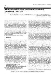
Fig. 1: Overview of the High-accuracy correspondence matching. k ≤ M . The 1D POC function r(n) between f (n) and g(n) is given as the 1D Inverse DFT (1D IDFT) of R(k). When two images are similar, their POC function gives a distinct sharp peak. When two images are not similar, the peak drops significantly. The height of the peak gives a good similarity measure for image matching, and the location of the peak shows the translational displacement between the images. We also employ the important techniques for improving the accuracy of 1D image matching for subpixel correspondence matching: (i) function fitting for highaccuracy estimation of peak position, (ii) windowing to reduce boundary effects, (iii) spectral weighting for reducing aliasing and noise effects and (iv) averaging 1D POC functions to improve peak-to-noise ratio [2]. In the case of a rectified stereo image pair, the disparity can be limited to horizontal direction [1]. The use of 1D POC makes it possible to achieve high-accuracy correspondence matching with low computational cost. In order to find the accurate correspondence from a stereo image pair, we employ the sub-pixel correspondence matching using POC. Figure 1 shows an overview of the high-accuracy correspondence matching which employs a coarse-to-fine strategy using image pyramids for robust correspondence search. Let p be a coordinate vector of a reference pixel in the reference image I(n1 , n2 ). The problem of sub-pixel correspondence search is to find a real-number coordinate vector q in the input image J(n1 , n2 ) that corresponds to the reference pixel p in I(n1 , n2 ). We briefly explain the procedure as follows. Step 1: For l = 1, 2, · · · , lmax − 1, create the l-th layer
images Il (n1 , n2 ) and Jl (n1 , n2 ), i.e., coarser versions of I0 (n1 , n2 ) and J0 (n1 , n2 ), recursively as follows: Il (n1 , n2 ) =
1 1 1 ∑ ∑ Il−1 (2n1 + i1 , 2n2 + i2 ), 4 i =0 i =0
Jl (n1 , n2 ) =
1 1 1 ∑ ∑ Jl−1 (2n1 + i1 , 2n2 + i2 ). 4 i =0 i =0
1
1
2
2
Step 2: For every layer l = 1, 2, · · · , lmax , calculate the coordinate pl = (pl1 , pl2 ) corresponding to the original reference point p0 recursively as follows: pl
= ⌊ 21 pl−1 ⌋ = (⌊ 12 pl−1 1 ⌋, ⌊ 21 pl−1 2 ⌋),
(2)
where ⌊z⌋ denotes the operation to round the element of z to the nearest integer towards minus infinity. Step 3: We assume that qlmax = plmax in the coarsest layer. Let l = lmax − 1. Step 4: From the l-th layer images Il (n1 , n2 ) and Jl (n1 , n2 ), extract two sub-images (or search windows) fl (n1 , n2 ) and gl (n1 , n2 ) with their centers on pl and 2ql+1 , respectively. The image blocks consist of L lines of N -point 1D signal. Step 5: Estimate the displacement between fl (n1 , n2 ) and gl (n1 , n2 ) with pixel accuracy using POC-based image matching. Let the estimated displacement vector be δl . The l-th layer correspondence ql is determined as follows: ql
= 2ql+1 + δl .
(3)
92
Int'l Conf. Par. and Dist. Proc. Tech. and Appl. | PDPTA'15 |
Step 6: Decrement the counter by 1 as l = l − 1 and repeat from Step 4 to Step 6 while l ≥ 0. Step 7: From the original images I0 (n1 , n2 ) and J0 (n1 , n2 ), extract two image blocks with their centers on p0 and q0 , respectively. Estimate the displacement between the two search windows with sub-pixel accuracy using POC-based image matching. Let the estimated displacement vector with sub-pixel accuracy be denoted by δ = (δ1 , δ2 ). Update the corresponding point as follows: q
= q0 + δ.
(4)
3. FPGA Implementation 3.1 FPGA Programming Model in OpenCL Figure 2 shows the thread space in OpenCL that has hierarchical structure where the overall computation consists of workgroups. The each workgroup is a set of workitems; a workitem is equivalent to a thread. When designing a kernel, we implement processing for the workitem. Figure 3 shows the memory model in OpenCL. The global and constant memories can be accessed by any workitem; the difference between global and constant memories is that the global memory is a read/write memory while the constant memory is a read-only memory. The local memory belongs to the workgroup, and the private memory to the workitem. In OpenCL for FPGAs, we can change the size of local and private memories flexibly unlike OpenCL for GPUs. Moreover, a recent high-end FPGA like Stratix V has a large local memory of 50M bits. This good nature of OpenCL for FPGAs can allow us to fully reuse data that are once retrieved from the global and constant memories. As a result, we can exploit the memory bandwidth efficiently. To fully reuse data based on this flexibility of memory structure, we use the following techniques: • store all coefficients for filters and FFT in the constant memory. • store the pre-calculated results for resource-consuming calculations such as division and square root. • cache-oriented design. In OpenCL for FPGAs, a private cache is created for each read-only data array in the global memory. Another big difference between OpenCL designs for FPGAs and GPUs is that pipelining can be efficiently exploited in FPGAs. Figure 4 shows the relation between a kernel and pipelining. Each instruction in a kernel is implemented as a pipeline stage in a pipeline as shown in Fig. 4 (a). The threads are fed into the kernel pipeline sequentially. This programming style is also effective to save memory bandwidth while keeping the performance (throughput). On the other hand, in OpenCL GPUs, the threads are processed in a data parallel manner which requires a large memory bandwidth. In order to fully exploit the advantages of pipeline design,
OpenCL for FPGAs supports “Channel” which can connect the different kernels using FIFO buffers. Figure 5 shows the overall structure of the POC-based correspondence matching using channels. The functions of the kernels are as follows: make high layer: generating the coarse images clip image: clipping the search windows from images fft1d: Fourier transformation for 1-D data eval cps: computing cross-power spectrum reorder: reorder data for the following ifft1d ifft1d: inverse Fourier transformation for 1-D data find peak: find correspondence by searching a peak Channels can be used for passing data to kernels and synchronizing kernels. The intermediate data are stored and fed to the next kernel through channels without the global memory. Therefore, the efficient data reuse can be achieved easily. In fact, 10 000 correspondence results are generated in the find peak kernel, and they are fed to the clip image kernel through the channel without other memories in the POC matching shown in Fig. 5 (b).
3.2 Evaluation For evaluation, we implement the POC-based stereo correspondence matching on a CPU, GPUs, and an FPGA as shown in Table 1. The parameters for the POC-based stereo matching are as follows: The size of the search window is 32 pixels × 15 lines, the number of layers is 4 and the number of reference points is 10 000. As a CPU, we use Core i7-3960X that has 6 cores (12 threads) running at a clock frequency of 3.3GHz−3.9GHz. As GPUs, we use Geforce GTX 580 and Geforce GTX 680 from NVIDIA corp. As an FPGA board, we use PCIe-395 D8 from Nallatech corp. that has a Stratix V FPGA from Altera corp. and 4 DDR3 memories. The maximum frequency of the FPGA design is 167MHz. Table 2 summarizes the resource utilization of the FPGA design, where the upper and lower rows are the specifications of the FPGA (Stratix V D8) and the used resources, respectively. For evaluation metrics, we use the processing time, power consumption, and power-delay product of each implementation. We measure the power consumption of a whole computer during execution with a power meter (HIOKI AC/DC POWER HiTESTER 3334). Note that, in Table 1, the power consumption is the difference between those of idle and operation state. A power-delay product is defined as the product of the processing time and the power consumption and represents the energy for computation, that is, efficiency. The GPU implementations are 25-27 times faster than the CPU implementation with a single thread and also 4.0-4.3 times faster than the CPU implementation with 12 threads (6 cores). The FPGA implementation is 17 times faster than the single-thread CPU implementation, and 2.7 times faster than the 12-thread CPU implementation. In terms of the processing time, the FPGA implementation has almost same performance as the GPU implementations although the FPGA’s
Int'l Conf. Par. and Dist. Proc. Tech. and Appl. | PDPTA'15 |
Fig. 2: Thread space in OpenCL.
Fig. 3: Memory Model in OpenCL.
Fig. 4: Pipelining in OpneCL for FPGAs.
93
94
Int'l Conf. Par. and Dist. Proc. Tech. and Appl. | PDPTA'15 |
Fig. 5: Overall structure using channels. Table 1: Performance and power comparisons among CPU-, GPU-, and FPGA-implementations.
*1 Power consumption is the difference between those of the idle time and operating state. *2 Nallatech PCIe-395 D8 have a Stratix V FPGA (Altera Corp.). Table 2: Resource utilization of the FPGA design.
memory bandwidth is much smaller than the GPU’s one. The power-delay products of the GPU implementations are about 8.0-8.4% of the single-thread CPU implementation, and 1920% of the 12-thread CPU implementation. The power-delay product of the FPGA implementation is 1.5% of the singlethread CPU implementation, 3.7% of the 12-thread CPU implementation, 20% of the GPU implementation (GTX 580), and 19% of the GPU implementation (GTX 680). The above results demonstrate that the FPGA implementation is much faster and much energy-efficient than the CPU implementations, and that the FPGA implementation has the almost same speed as the GPU implementations and is much energy-efficient.
4. Application example: Real-time 3-D measurement system Figure 6 shows that we develop a real-time and accurate 3D measurement system using a moving consumer digital camera. In this system, a set of images taken different viewpoints are used for the 3D measurement system. One of the well-known 3D measurement methods is Structure from Motion (SfM) using feature-based correspondence matching [1]. However, only a limited number of 3D points are measured by this method and are not sufficient to measure the fine 3D shape of the object. Addressing this problem, our system employs the algorithm combining SfM using feature-based matching to estimate camera parameters and the POC-based correspondence matching to obtain dense correspondence. As shown in Fig. 7, the procedure of the proposed system consists of 3 steps: (i) correspondence matching based on
Int'l Conf. Par. and Dist. Proc. Tech. and Appl. | PDPTA'15 |
Fig. 6: Experimental 3D measurement system using consumer digital camera.
95
Fig. 7: Processing flow of the proposed system: (a) input stereo image pair, (b) result of SIFT-based correspondence matching, (c) rectified stereo image pair, (d) result of POC-based correspondence matching and (e) 3D measurement result.
Fig. 8: Results of 3D measurement: (a) input stereo image pair, (b) 3D points measured by SIFT-based SfM (2790 points) and (c) 3D points measured by the proposed procedure (25 243 points).
Scale-Invariant Feature Transform (SIFT) [8], (ii) camera parameter estimation [1] and (iii) 3D shape measurement [9]. In the step (iii), we employ the POC-based stereo correspondence matching implemented on the FPGA board. Figures 8 (b) and (c) show 3D measurement result of the stereo image pair using SIFT-based SfM and the proposed procedure, respectively. The size of images is 1280×960 pixels. The measurement result using the proposed procedure has 25 243 points from two snapshots, while the result using SIFT-based SfM has only 2790 points. The FPGA implementation of the POC-based stereo correspondence matching makes it possible to obtain dense 3D points of an object in a few seconds. Moreover, its highenergy efficiency would allow the total computing system to be embedded into the camera system.
5. Conclusion This paper has proposed the FPGA implementation of the POC-based stereo correspondence matching using OpenCL for high-speed and low-power consumption. The key to success is to exploit the pipelining and to fully reuse data based on the flexibility of memory design. As future work, we are planning to generalize the design methodology for this dedicated processor aiming at automatic generation of FPGA-oriented OpenCL codes from other codes such as GPU-oriented OpenCL codes and C/C++ codes.
References [1] R. Szeliski, Computer Vision: Algorithms and Applications ], London; New York, Springer-Verlag, 2011. [2] T. Shibahara, T. Aoki, H. Nakajima, and K. Kobayashi, “A sub-pixel stereo correspondence technique based on 1D phase-only correlation,” in Proc. ICIP 2007, pp. V–221–V–224, 2007. [3] M. Miura, K. Fudano, K. Ito, T. Aoki, H. Takizawa, and H. Kobayashi, “Performance evaluation of phase-based correspondence matching on GPUs,” in Proc. SPIE 8856, Applications of Digital Image Processing XXXVI, pp. 1–9, 2013. [4] Khronos Group. (2010) The OpenCL Specification. [Online]. Available: https://www.khronos.org/registry/cl/specs/opencl-1.0.48.pdf [5] Altera SDK for OpenCL. [Online]. Available: https://www.altera. com/products/design-software/embedded-software-developers/opencl/ overview.html [6] C. D. Kuglin, and D. C. Hines, “The phase correlation image alignment method,” in Proc. Int’l Conf. Cybernetics and Society, pp. 163–165, 1975. [7] K. Takita, T. Aoki, Y. Sasaki, T. Higuchi, and K. Kobayashi, “Highaccuracy subpixel image registration based on phase-only correlation,” IEICE Trans. Fundamentals, Vol. E86-A, No. 8, pp. 1925–1934, Aug. 2003. [8] D. G. Lowe, “Distinctive image features from scale-invariant keypoints,” Int’l J. of Computer Vision, Vol. 60-2, pp. 91–110, Nov. 2004. [9] M. Miura, S. Sakai, J. Ishii, K. Ito, and T. Aoki, “An easy-to-use and accurate 3D shape measurement system using two snapshots,” in Proc. IWAIT 2013, pp. 1103–1106, 2013.