International Journal of Electrical and Computer Engineering (IJECE) Vol. 6, No. 2, April 2016, pp. 504~511 ISSN: 2088-8708, DOI: 10.11591/ijece.v6i2.9184
504
Optimal Location of Distributed Generation and its Impacts on Voltage Stability Manoj Kumar Nigam, V.K. Sethi Department of Electrical Engineering, R.K.D.F. University, Bhopal, M.P., India
Article Info
ABSTRACT
Article history:
Distributed generation (DG) technology is based on the renewable sources of energy. Now a day’s distributed generation plays an important role of power generation utilities to fulfill the increasing demand of power at the costumer’s site. A distributed generation is the small generation unit with capacity varying from kW (kilowatt) to few MW (megawatt). The main aim of this paper is to find the solution for optimal location of connecting DG and also the disturbances in the voltage fluctuations responds to imperfection of connecting DG. A test network of IEEE-30 bus system has been simulated using PSAT 2.1.7. The compensation methods have also been developed for filtering out the disturbances caused by the DG connection. The disturbance in the voltage profile is improved byminimizing the real and reactive power losseswith the help of STATCOM. The proposed approach IEEE-30-bus system was tested and the result was discussed.
Received Oct 12, 2015 Revised Dec 12, 2015 Accepted Jan 3, 2016 Keyword: Compensation Distributed generation Green house gases Network grid Renewable sources
Copyright © 2016 Institute of Advanced Engineering and Science. All rights reserved.
Corresponding Author: Manoj Kumar Nigam Department of Electrical Engineering, RKDF University. Airport Bypass Road, Gandhi Nagar, Bhopal, Madhya Pradesh 462033, India Email:
[email protected]
1.
INTRODUCTION The existing methods of power generation employs a central power generation plant which is either a nuclear power plant or a coal based power plant to generate the power in thousands of MW (megawatt). Typical methods were undertaken in these power plants for the combustion of coal, oil and other natural resources. These methods produces environmental disturbances, health issues in human beings, emission of green house gases etc. wherein the generated power is to be transmitted over a long distance through transmission line to reach to the costumers at far off places and creates the losses due to increased length of transmission line. To minimize these effects, DG may be installed at the costumer’s site that employs small-scale technologies to produce electricity close to the end users. DG technologies offer a number of potential benefits consisting modular (and sometimes renewable-energy) generators. In many cases, distributed generators can provide lower-cost electricity and higher power reliability and security with fewer environmental consequences than the traditional power generators. In view of the use of a few large-scale generating stations located at quite away from load centers, DG systems employ numerous small power plants and may be useful to provide power with a little dependence on the distribution and transmission grid. DG can be defined as the installation and operation of electric power generation units connected directly to the distribution networks or connected to the network on the customer of the meter [1]. Thus, a DG technology offers several advantages like: It accelerates the system flexibility to supply power demand at fluctuating loads with minimum environmental disturbances, Lesser ill effects on human health, Journal homepage: http://iaesjournal.com/online/index.php/IJECE
505
ISSN: 2088-8708
Economical installation, Utilization of non-renewable sources (viz. solar, tidal, wind) of energy for electricity production, Reduces the length of the transmission line at costumers’ site etc. Despite of several advantages, the DG may be installed on priority into the existing grid network at the optimal location otherwise it may be harmful to costumers’ site. Installation of DG creates some disturbances if not placed at the optimal location- it disturbs the power flow in the network by disturbing the voltage profile at the junction of its connection, poor stability, increased power losses etc. An increase in the fault level of the power system may cause large fault clearing time and require disconnection of equipment in the distribution system during operation of protective devices. Overall, it is to be in our mind that protection of system is an important aspect and it is necessary to connect the DG at the optimal location in order to have lesser disturbances Methods like ant colony optimization [2], particle swarm optimization [3-4], monte-carlo simulation methods [5] genetic algorithm [6] and optimal power flow method [7] have been discussed. A method is being introduced thatfour types of DG are considered with one DG installed for minimize the total real and reactive power losses. The main aim of this methodology is to calculate size and to identify the corresponding optimum location for DG placement to minimize the totalreal power and reactive power losses and to improve voltage profile [8]. PV bus is the bus where we put the values of active power and magnitude of voltage and DG is connected to the distribution grid through the synchronous generator with excitation control mode for voltage control, the PQ bus is the bus at which input values of active power and reactive power inserted. On the other hand in PQ bus the DG is connected to the distribution grid through synchronous generator with excitation control mode for power factor control [9]. S.P. Rajaram et al. suggested that the optimal location of connecting DG in any network is the weakest node at which the maximum voltage drop occurs [10]. In this paper a new method have been suggested which is easy to operate and is very effective. The simulation of the IEEE 30 bus test network is done using Power System Analysis Tool (PSAT) of MATLAB. It was an approach to overcome the ill effects of the DG byusing FACT (Flexible AC Transmission) devices like SVC, synchronous condenser, STATCOM etc. A test of IEEE 30 bus network has been designed and simulated using PSAT 2.1.7. The method incorporated in the simulation of test network is the Newton Raphson method for analyzing the power flow in the network.
2.
VOLTAGE STABILITY Voltage stability is the ability of power systems to maintain steady voltage within permissible ranges at all buses in normal conditions and after having been subjected to a severe system perturbation. Voltage instability may result in significant disturbances of voltages on some buses. The main contributing factor to voltage instability is voltage drop that occurs when reactiveand active power flows in transmission lines. Consequently, it limits the capability of the transmission system for voltage support and power transfer. In addition, dynamic loads also contribute to the voltage instability when disturbance occurs. The load tends to respond by restoring the consumed power, which can increase reactive power consumption and the stress of high voltage network causes more voltage reduction. Voltage stability may be classified into two distinct sub-system categories: Large disturbance voltage stability refers to the ability of power systems to maintain and control voltages following large perturbations, such as loss of generation or system faults. Small disturbance stability refers to the ability of power systems to maintain and control voltages following small perturbations, such as incremental change in loads. Meanwhile, the duration time for voltage stability problems may vary from a few seconds to tens of minutes. Therefore, the extent of voltage stability could be a short-term or long-term phenomenon.
3.
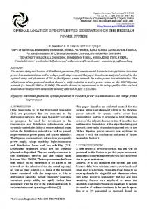
RESEARCH METHODOLOGY PSAT is a powerful power analyses tool of MATLAB. The IEEE 30 bus network has been designed using PSAT without DG connection, with DG connection and with DG and STATCOM both connected (Figure 1, Figure 2 and Figure 3) respectively. Amount of power flow in the network without DG connected and with DG connection, the optimal location for the connection of DG, the bus with the maximum voltage drop, from comparative study of high voltage drop it is found that the bus no. 29 and 30 showed the high voltage drop (Table-1 and Table-2) respectively. IJECE Vol. 6, No. 2, April 2016 : 504 – 511
IJECE
ISSN: 2088-8708
506
Figure 1. IEEE 30 bus network without DG connection
Figure 2. IEEE 30 bus network with DG connection
Optimal Location of Distributed Generation and its Impacts on Voltage Stability (Manoj Kumar Nigam)
507
ISSN: 2088-8708
Figure 3. IEEE 30 bus network with DG and STATCOM connection
4.
RESULT AND DISCUSSION Results obtained from the continuous power flow method shows the impact on the voltage profile of the network when DGsare connected at bus no. 29 and 30. The value of the voltage is decreases in most of the cases when DGs are connected in respective buses (Table 1 and Table 2) respectively. These disturbances in voltage profile caused by the interconnection of DG are eliminated and improve the magnitude of voltage near to 1.0 puin both weak buses 29 and 30 by the use of STATCOM (Table-3). The interconnection of DG is also disturbed the total generation of real and reactive power which is given below. The method suggested by Su Hlaing Win et al. If Different types of DG installed in the system have different impacts on minimization of reactive power loss, on the bases of loss reduction the optimal size and location of DG are also changed with different type of DG installed in the system. Authors have suggested a formula is used to determine optimal size and the location for type-1 to type-4 DG [8]. This method is very complicated for selection of proper rating and size of DG. In our test system it is very easy to find out the optimal location of DG and to minimize losses. Results obtained for load flow without DG Total Generation Real power [p.u.] Reactive power [p.u.] Total Load Real power [p.u.] Reactive power [p.u.] Total Losses Real power [p.u.] Reactive power [p.u.]
13.9588 20.138 9.3117 4.0149 4.6471 16.1231 Result of load flow with DG connected
Total Generation Real power [p.u.] Reactive power [p.u.] Total Load Real power [p.u.] Reactive power [p.u.] Total Losses Real power [p.u.] Reactive power [p.u.] IJECE Vol. 6, No. 2, April 2016 : 504 – 511
13.9605 20.1497 9.3093 4.0139 4.6512 16.1358
IJECE
ISSN: 2088-8708
508
Results of load flow with DG and STATCOM Total Generation Real power [p.u.] Reactive power [p.u.] Total Load Real power [p.u.] Reactive power [p.u.] Total Losses Real power [p.u.] Reactive power [p.u.]
0.0028 -1.0705 0.0 -1.0619 0.0028 - 0.00869
It is clear from the above result that total realpower loss is reduced from 4.6512 pu to 0.0028 pu and reactive power loss is reduced from 16.1358 pu to- 0.00869 puwith the above network configuration by using STATCOM to improve the voltage stability. It is therefore suggested that before connecting the distributed generation it is necessary that system designer must think of the compensation devices as well as location of the distributed generation so that the losses are minimum. The optimal size of the DG is also very important in reducing the losses. If a DG of any size is connected it will inject or absorbs active power thereby again disturbing the voltage profile of the associated network. The disturbances caused by the interconnection of DG are eliminated by the use of STATCOM.
Table 1. Power flow result without DG connection Bus Bus1 Bus2 Bus3 Bus4 Bus5 Bus6 Bus7 Bus8 Bus9 Bus10 Bus11 Bus12 Bus13 Bus14 Bus15 Bus16 Bus17 Bus18 Bus19 Bus20 Bus21 Bus22 Bus23 Bus24 Bus25 Bus26 Bus27 Bus28 Bus29 Bus30
Voltage (p.u.) 1 1 0.77822 0.79257 1 0.85474 0.87731 1 0.85428 0.77546 1 0.82312 1 0.74862 0.72304 0.76643 0.74989 0.67757 0.6677 0.69 0.71068 0.71168 0.66704 0.63608 0.65423 0.54677 0.71943 0.83797 0.55653 0.45864
Optimal Location of Distributed Generation and its Impacts on Voltage Stability (Manoj Kumar Nigam)
509
ISSN: 2088-8708 Table 2. Power flow result with DG connection Bus Bus1 Bus2 Bus3 Bus4 Bus5 Bus6 Bus7 Bus8 Bus9 Bus10 Bus11 Bus12 Bus13 Bus14 Bus15 Bus16 Bus17 Bus18 Bus19 Bus20 Bus21 Bus22 Bus23 Bus24 Bus25 Bus26 Bus27 Bus28 Bus29 Bus30
Voltage (p.u.) 1 1 0.77808 0.79242 1 0.85459 0.87723 1 0.74846 0.72283 0.76627 0.7497 0.67737 1 0.85414 0.77525 1 0.82299 0.66749 0.68979 0.71042 0.7114 0.66671 0.6356 0.65332 0.54566 0.71835 0.83757 0.5542 0.45544
Table 3. Power flow result with DG and STATCOM connection Bus Bus1 Bus2 Bus3 Bus4 Bus5 Bus6 Bus7 Bus8 Bus9 Bus10 Bus11 Bus12 Bus13 Bus14 Bus15 Bus16 Bus17 Bus18 Bus19 Bus20 Bus21 Bus22 Bus23 Bus24 Bus25 Bus26 Bus27 Bus28 Bus29 Bus30
IJECE Vol. 6, No. 2, April 2016 : 504 – 511
Voltage (p.u.) 1 1 1.0013 1.0015 1 1.0087 1.0051 1.0148 1.0226 1.0368 1 1.0267 1 1.0281 1.029 1.0311 1.0351 1.0321 1.0337 1.0346 1.036 1.0358 1.0303 1.0318 1.0114 1.0116 0.99821 1.0129 0.99868 0.99873
IJECE
ISSN: 2088-8708
510
Figure 4. Voltage profile without DG connection
Figure 5. Voltage profile with DG connection
Figure 6. Voltage profile with DG and STATCOM
5.
CONCLUSION It is concluded that the voltage profile of the network is improved when the DG is connected to system. The bus no. 26, 29 and 30 are found to be the preferred location for the connection of the distributed generation with the weakest bus no. 29 and 30 had being the optimal location for the connection of the DG. The IEEE 30 bus network is first simulated without DG connection and the results obtained were compared Optimal Location of Distributed Generation and its Impacts on Voltage Stability (Manoj Kumar Nigam)
511
ISSN: 2088-8708
with the simulation result of the network with DG connection. The graphs shows the voltage profile of without DG connection and with DG connection (Figure 4, Figure 5) respectively. Disturbances caused by the integration of DG were eliminated by using the FACT device (STATCOM) (figure 6). It is advisable to first determine the optimal location of DG to minimize the losses caused by the DG connection before integrating the DG into the network.
REFERENCES [1] Thomas Ackermann, Goran Andersson, and Lennart Soder Distributed Generation: a definition. ELSEVIER Electric Power Systems Research. 2001; 57(3): 195-204. [2] Hamid Falaghi, Mahmood-Reza Haghifam. ACO Based Algorithm for Distributed Generation Sources Allocation and Sizing in Distribution Systems. Power Tech2007 IEEE Lausanne. 2007; 555-560. [3] Hossein Shahinzadeh, Sayed Mohsen Nasr-Azadani, Nazereh Jannesari. Applications of Particle Swarm Optimization Algorithm to Solving the Economic Load Dispatch of Units in Power Systems with Valve-Point Effects. International Journal of Electrical and Computer Engineering (IJECE). 2014; 4(6): 858~867. [4] M.F. Alhajri, M.R. AlRashidi, and M.E. El-Hawary. Hybrid Particle Swarm Optimization Approach for Optimal DistributionGeneration Sizing and Allocation in Distribution Systems. IEEE. 2007; 1290-1293. [5] Walid El-Khattam, Y.G. Hegazy, and M.M.A. Salama. Investigating Distributed Generation Systems Performance Using Monte Carlo Simulation. IEEE Trans. Power System. 2006; 21(2):524-532. [6] Deependra Singh, Devender Singh, and K.S. Verma. Multiobjective Optimization for DG Planning With Load Models. IEEE Trans. Power System. 2009; 24, (1): 427-436. [7] Chris J. Dent, Luis F. Ochoa, and Gareth P. Harrison. Network Distributed Generation Capacity Analysis Using OPF With Voltage Steps Constraints. IEEE Trans. Power System. 2010; 25(1): 296-304. [8] Su Hlaing Win, Pyone Lai Swe.Loss Minimization of Power Distribution Network using Different Types of Distributed Generation Unit. International Journal of Electrical and Computer Engineering (IJECE). 2015; 5(5): 918~928. [9] JIANG Fengli, ZHANG Zhixia, CAO Tong, HU Bo, PIAO Zailin. Impact of Distributed Generation on Voltage Profile and Losses of Distribution System.32nd Chinese Control Conference. Xi’an, China. 2013; 8587-8591. [10] S.P. Rajaram, V. Rajasekaran, and V. Sivakumar, Optimal Placement of Distributed Generation forVoltage Stability Improvement and Loss Reduction in Distribution Network. IJIRSET. 2014; 3(3): 529-543.
BIOGRAPHIES OF AUTHORS Manoj Kumar Nigam, received the B.E. and ME degree in Electrical Engineering from MITS Gwalior, M.P., India. He has more than 12 years of experience inteaching and research and is a Ph.D. Scholar in Electrical Engineering in R.K.D.F University, Bhopal (M.P), India. His current research focuses on Distributed generation, power electronics drives and power quality Issues in the Power System.
Dr. V.K. Sethi, received the BE (Hons.) from IIT Roorkee, PG from UK and Ph. D from IIT Delhi, He was Scientist ‘C’ Department of Atomic Energy, BARC, Bombay, Asst. Director, Deputy Director (Faculty) Ministry of Power, Deputy Director (Site), Director Ministry of Power, Central Electricity Authority and Ex. Director MOP/CEA, EX-Rector & Director, RGPV, Bhopal and is now a Vice Chancellor RKDF University, Bhopal (MP), India. He has published 115 research papers in reputed national, international journals and conferences he is an authors of 12 books. His research interests are power plant engineering, Renewable Energy, Green Power Technologies & CDM Opportunities
IJECE Vol. 6, No. 2, April 2016 : 504 – 511