ing the orientation estimate of a mobile robot. ... aerospace applications [4, 61 but have yet to be seriously ... estimate of a robot with respect to its environment.
Orientation Estimate for Mobile Robots using Gyroscopic Information Billur Barshan Department of Electrical Engineering Bilkent University Bilkent, TR-06533 Ankara, Turkey and Hugh F. Durrant-Whyte Robotics Research Group Department of Engineering Science University of Oxford Oxford, OX1 3PJ United Kingdom
Abstract An error model for a solid-state gyroscope developed in previous work is included in a Kalman filter for improving the orientation estimate of a mobile robot. Orientation measurement with the error model is compared to the performance when no error model is incorporated in the system. The results demonstrate that without error compensation, the error in localization is between 5-15"/min but can be improved by a factor of 5 to 7 if an adequate error model is supplied. Results from tests of this gyroscope on a large outdoor mobile robot system are described and compared to the results obtained from the robot's own radar-based guidance system. Like all inertial systems, the platform requires additional information from some absolute position sensing mechanism to overcome long-term drift. However, the results show that with careful and detailed modelling of error sources, low cost inertial devices can provide valuable orientation and position information particularly for outdoor mobile robot applications.
1
Introduction
Inertial navigation systems (INS) are self-contained, nonradiating, nonjammable, dead-reckoning navigation systems which provide dynamic information through direct measurements. In most cases an INS must be integrated with other absolute location sensing mechanisms to provide useful information about vehicle position. Models that describe the outputs of inertial sensors sufficiently accurately are essential if the information is to be used effectively. Fundamentally, gyros provide angular rate information and accelerometers provide velocity rate information. Although the rate information is reliable over long periods of time, it must be integrated to provide absolute measurements of orientation, position and velocity. Thus, even very small errors in the rate information provided by
inertial sensors cause an unbounded growth in the error of integrated measurements. As a consequence, an INS by itself is characterized by position errors that grow with time and distance. One way of overcoming this problem is to periodically reset inertial sensors with other absolute sensing mechanisms and so eliminate this accumulated error. In robotics applications, a number of systems have been described which use some form of absolute sensing mechanisms for guidance (see [4] or [5] for surveys). Such systems typically rely on the availability of easy to see beacons or landmarks, using simple encoder information to predict vehicle location between sensing locations. This works well when the density of beacons or landmarks is high and the ground over which the vehicle travels is relatively smooth. In cases where the beacon density is sparse or the ground is uneven, such systems can easily lose position track. This is particularly a problem for vehicles operating in outdoor environments. Inertial navigation systems can potentially overcome this problem. Inertial information can be used to generate estimates of position over significant periods of time independent of landmark visibility and of the validity of encoder information. Clearly, positions derived from inertial information must occasionally be realigned using landmark information, but a system that combines both inertial and landmark s e n s ing can cope with substantially lower landmark density and can also deal with terrain where encoder information has limited value. Inertial navigation systems have been widely used in aerospace applications [4, 61 but have yet to be seriously exploited in robotics applications where they have considerable potential. For a robotic INS, both the scale, nature and parameters of the localization problem are different than in aerospace. Hence, INS'S developed for aerospace applications cannot be directly implemented on mobile ground vehicles. In addition, systems developed for aerospace are far too expensive to be used robotics applications. In [lo], the integration of inertial and visual
1867
and to use this directly in a Kalman filter to estimate position before supplementing the robot with absolute sensing mechanisms. In the next section, we decribe the gyroscope used in this work for orientation estimation. In Section 3, we summarize earlier results on error modelling for the gyro. In Section 4, the error model is used to augment a orientation-estimating Kalman filter for error compensation. Section 5 describes the testing of the gyroscopic system on a radar-guided land vehicle. Accurate vehicle position fixes from the radar guidance system in a dense beacon environment are compared against position and orientation information predicted by the INS. In conclusion, we discuss the usefulness of low-cost inertial devices in robotics applications, for outdoor vehicles and also for indoor guidance systems.
2
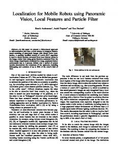
Figure 1: The ENV-05s Gyrostar manufactured by Murata. information is investigated. Methods of extracting the motion and orientation of the robotic system from inertial information are derived theoretically but not directly implemented in a real system. In [9], inertial sensors are used to estimate the attitude of a mobile robot. With the classical three-gyro, two-accelerometer configuration, experiments are performed to estimate the roll and pitch of the robot when one wheel climbs onto a plank using a small inclined plane. One reason that inertial systems are widely used in aerospace applications but not in robotics applications is simply that high-quality aerospace inertial systems are comparatively too expensive for most robotics systems. However, low-cost solid-state inertial systems, motivated by the needs of the automotive industry, are increasingly being made commercially available. Although a considerable improvement on past systems, they clearly provide substantially less accurate position information than equivalent aerospace systems. However, as we describe in this paper, such systems are at a point that, by developing reasonably detailed models of the inertial platform, these sensors can provide valuable information i n many robot positioning tasks. 'rhe primary motivation for the work reported in this paper has been the need to develop a system capable of providing low-cost, high-precision, orientation information for large outdoor automated vehicles. In particular, we are interested in obtaining orientation information for short periods when the vehicle is not in contact with any beacon or landmark information. The approach taken in this paper is to incorporate in the system a przorr inforrnation about the error characteristics of the inertial sensors
Description of the Gyroscope
A fundamental requirement for an autonomous mobile robot is the ability to localize itself with respect to the environment. In this paper, we focus on the orientation estimate of a robot with respect to its environment. In previous work [a], two different types of gyroscopes have been considered and evaluated: the Solid STate Angular Rate Transducer (START) gyro manufactured by GEC Avionics and the ENV-05s Gyrostar manufactured by Murata [8]. As a result of the evaluation experiments whose results are provided in [a], the Gyrostar was chosen for the robotic INS since it proved to perform better than the START in addition to being more compact, light and very inexpensive. For a picture of the solid-state rate gyroscope Gyrostar, refer to Figure 1. The Gyrostar is a small relatively inexpensive piezoelectric gyro originally developed for the automobile market and active suspension systems [8]. The main application of the Gyrostar has been in helping car navigation systems to keep track of turns for short durations when the vehicle is out of contact with reference points derived from the additional sensors. The maximum rate that can be measured with Gyrostar is f 9 0 ° / s within its linear range.
3
Error Modelling of Inertial Sensors
Error modelling for solid-state gyroscopes have been extensively discussed in [3]. It has been shown that an apparently small time-varying bias is characteristic of these gyros as illustrated in Figure 2. The time variation of the bias is attributed to thermal effects based on the observation that the gyro units gradually heat up during operation. The bias can taper off to a negative or positive value depending on the ambient temperature. This type of bias error can be suitably described by an exponential error model whose details are given below. In the following, let ~ ( 1 )be the bias error associated with measuring the true value of a quantity of interest using Gyrostar. A nonlinear parametric model of the
1868
AID output
= 2048
(w+ 1)
with initial conditions c&(O) = CZand l i ( 0 ) = discretization Equation 2 becomes
%. After
with c k ( 0 ) = Cz. Due to its recursive nature, thie difference equation is independent of start-up time but relies on a good estimate of the initial bias. The only observation is the erroneous rate output of the gyro which corresponds to the true value of the rate plus the bias error. To provide additional information to the filter, the rate output of the gyro is numerically integrated and fed to the filter as an observation: I
"1
time( hours)
2025
I
Figure 2: Digitized angular rate output of the Gyrostar when subjected to zero input. or in matrix notation:
following form was fitted to the data from the gyro using the Levenberg-Marquardt iterative least-squares fit method [ll]: €model ( t ) = c 1 (1
- e-')
+ CZ
(1)
where cmodel(t) is the fitted error model to the gyro output when zero input was applied, with parameters Cl, CZ, T to be tuned. Starting with reasonable initial guesses for the parameters, convergence to a local minimum is achieved within 5-10 iterations. Best fitting parameters for Gyrostar are C1 = 0.153'/s, C2 = -0.264'1s and TI = 5.64 min. The sufficiency of the above model in Equation 1 has been determined by applying a whiteness test to the residuals in the autocorrelation domain [3]. The positive outcome of the whiteness test on the model residuals demonstrates that the model in Equation 1 adequately represents the slowly varying bias error on the rate output of the Gyrostar. In the next section, we exploit these the error models in a Kalman filter to compensate for the errors.
4
Implementation of the Gyro Error Model
The parametrized model of Equation 1 for the bias error can be represented by the following differential equation:
z(k) = H@(k) + v(k) where v l ( k ) and v2(k) are white measurement noise proCe88e8. Given the erroneous observations, the states that need to be estimated are the true values of Orientation, angular rate and the errors associated with them. Hence, the state equations of the Kalman filter are augmented by Equation 3 and its integral to estimate and compensate for the sensor errors. The resulting state equations of the filter are as follows:
].[i
1 0
T.
3T,2
1 0
T.
0 0
1 0 0
0
0
0
0
or in matrix notation:
@(k
+ 1) = FO(k) + U -tw(k)
(7)
The first four states are the true values of the orientation and its derivatives, and the last two states constitute the error model for the gyroscope. Note that the error states
1869
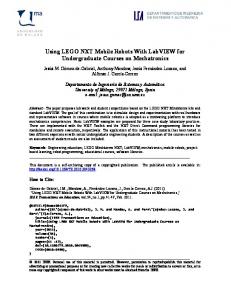
Figure 3: FRAIT 80 vehicle at the Firefly Ltd. test site.
are coupled to the relevant true states only through the observations and not by the structure of the state transition matrix F. In setting the covariance matrix Q for the process noise w(k), continuous-time white-noise model assumption has been made as described in [l]. This assumption leads to the following process noise covariance matrix:
Q = E{w(k)wT(k)} =
I
o
0 0
0 0
Ts fl: 0 0
zu2 $2
$4
where vu = 0.05°/sec3, and the U, is the standard deviation of the residuals from the fitted model experimentally determined to be 2.14 A/D units or 0.2’/sec. The state vector estimated by the filter is given by
+ Ilk + 1) = F&(kIk) + U + W(k + l ) v ( k + 1) (9) where W(k+l) is the filter gain and v ( k + l ) = z(k + 1)H&(k + Ilk) is the innovations vector provided by the &(k
+
new observations at time (k l)Ts. A detailed treatment of Kalman filter prediction and update equations can be found in [l]. The above filter has a constant 6 (k) structure augmented by the error model. Lower-order filters have been implemented but shown to have a delay and much ringing in their unit-step response. With this higher order model, the filter is able to track abrupt changes in angular velocity very closely. An important point to note is that all states, including drift parameters, are estimated at every sample time. The filter structure in Equations 4 and 6 has been implemented in real time on an INMOS-T805 transputer network where a minimum sampling interval of T,=30 ms is achieved. The gyro has been mounted on a rotating platform whose angular velocity and orientation can be accurately controlled and measured. A 500 line optical encoder was used to measure motor position, driving the platform through a low backlash 20:l gear box. An HCTL-1100 chip was used to control the motor in the integral velocity mode. For comparison purposes, the platform velocity and orientation are taken t o be the “true” values of these quantities in the next section. An initial estimate of the bias, E ~ ( O ) ,is made t o initialize the filter by averaging the output of the gyro over a large number of samples when there is no rotational motion. Since the start time of the experiment can correspond to any point on the curve in Figure 2, it is important to have a good estimate of the
1870
initial bias. For an initial estimate over 2,000 samples, data collection and estimation takes only 1-2 sec on a n 1 5 0 INMOS-T805 transputer hosted by an IBM-80486 PC. As data is collected by the gyroscope, the Kalman filter process running in parallel filters the measurements and provides estimates of orientation, its derivatives and the state of the bias error. 100 The gyro was tested under laboratory conditions, first under zero input conditions, and subsequently when subject to known input motions. These were used to provide preliminary estimates of orientation estimate errors. A number of conclusions from these tests were made and these results were presented in [2]. Using an error model, 50 accuracy was improved approximately by a factor of 5 - 7.
5
Testing of the INS on a Land Vehicle
The INS has undergone tests on an automated land vehicle provided by Firefly Ltd. and pictured in Figure 3. The vehicle weighs 19 tonnes and is designed to carry IS0 I I standard cargo containers up to a capacity of 80 tonnes.-50 -100 0 100 200 It is powered by diesel hydraulic drives and can achieve speeds up to 6 m/s. It has a dual-Ackerman steer configuration with both front and rear wheels steering indepenY(m) dently to allow crabbing motions. Tyres are conventional , I I I pneumatic tyres with no suspension. The main vehiclel50 guidance system consists of two frequency-modulated continuous wave millimeter-wave radar systems operating at 94 GHz with a swept bandwidth of 500 MHz. These provide range and bearing information to a set of 12 special radar reflectors placed around the test area. The range resolution is 10 cm, the bearing resolution approximately 1’ and the maximum range about 200 m . Beacon bear- 100 ing and range measurements are used to compute location and velocity estimates of the vehicle with respect to a fixed beacon map. The absolute accuracy of the guidance system is approximately 3 cm over the test area. Since the information provided by the radar is very accurate and does not drift with time, this is used as an “absolute” reference to compare the accuracy of the orientation data 50 provided by Gyrostar. Ultimately, the aim of the gyroscope is to aid the radarbased navigation system in areas where beacon observations are infrequent, and for new vehicles travelling at substantially higher speeds where increased short-term accuracy is rkquired. In such situations, the state estimator is I I I used to provide improved short-term predictions between 0 -5 0 5 10 15 beacon observations which are then integrated in a subsequent navigation filter which incorporates a model of 4m) vehicle kinematics. This is known as a feed-back filter configuration. This should be contrasted with a feed- Figure 4: 2: - y position of the FRAIT 80 vehicle as estiforward filter configuration in which the Kalman filter mated by the radar for two different runs. incorporates the vehicle model and beacon observations are used to correct the estimates produced by this filter [7]. Consequently, the experimental results described here concentrate on describing the stand-alone prediction performance of the gyroscope. 1871
10
I
100
I
5
50 0
-5 0
-15
1
I
-10
0
10
5
15
-50
5
0
10
15
time( min)
time( min)
40
5
I
'
I
'
I
'
I
'
I
'
20
0 0
-5 -20
-1 0
0
5
-40
10 time(min)
0
2
4
6
8
10
12
time(min)
Figure 5: The Gyrostar rate output data for two different runs.
1872
Figure 6 : Orientation estimate using the Gyrostar rate output and radar data for two different runs.
In Figure 4, the trajectory of the vehicle for two different runs is shown in the z - y coordinate frame (note the nonequal scaling of z - y axes). In each run, the vehicle starts off at (z,y)= (0,20), moves along the y axis and comes backwards to its starting point to continue along different trajectories. The duration of each run is different. In Figure 5, raw angular rate data from the gyroscope is shown for two runs. By filtering the Gyrostar rate output with error compensation, a vehicle orientation estimate is obtained a s illustrated in Figure 6 in dotted line. This result is compared t o the estimate from the radar shown in solid line. Since the radar data is very accurate, it is taken to be the true value of the orientation for purposes of evaluation. It can be seen that the orientation estimate produced from Gyrostar compares very well with the orientation estimate produced by the radar system. Over a run time of approximately 10 minutes, the maximum orientation error is of the order of 5". This is actually substantially better than predicted from the bench tests conducted on the gyro [2]. It is conjectured that this is because the turning motions of the vehicle are not as abrupt as those generated during bench testing and orientation estimates are generally good at following these turning motions. These results indicate that the gyro can be used t o provide reliable vehicle orientation information over relatively long periods of time of the order of 10 min and possibly longer. The nature of beacon-based navigation using some absolute sensing mechanism (like radar) requires that a good prediction of vehicle location is made at each time-step so that the process of matching observed beacons to a map of beacon locations (data-association) can be done accurately and efficiently. The gyro described in this paper provides a good means of providing such predictions particularly in situations when only sparse beacon layouts are available or when the vehicle is running at high speeds over rough terrain. Error in predicted vehicle orientation is a notable source of difficulties in beacon matching, because of instabilities arising from non-linearities involved in using the observation model to predict beacon location. The low-drift rates associated with gyro orientation estimates provides a direct means of minimizing such problems. Linear error in beacon matching is less of a problem because of the linear relationship between vehicle and beacon location errors. Practically, the FRAIT-80 vehicle described observes a beacon approximately 3 times a second to provide an accuracy of 5 cm at a speed of 6 m/s. The addition of inertial information will allow the same accuracy to be achieved with a reduction in beacon observation frequency to once every 2-3 s , or a speed increase to 12-15 m/s.
6
Discussion and Conclusion
substantial improvements in performance can be made which make the application of low-cost inertial navigation systems to mobile robot applications a viable proposition. We have described a Kalman filter which takes as input the measurements made by the gyro and produces estimates for the orientation, its derivatives, and the drift rate. This filter was used to test the gyro under laboratory conditions. These were used to provide preliminary estimates of orientation estimate errors. A number of conclusions from these tests were made, in particular, the orientation estimates obtained were reliable and useful over quite long time-periods. The drift models developed for these sensors substantially increased estimate accuracy. The gyro was tested on a radar-equipped land vehicle for evaluation and comparison purposes. The orientation estimates produced were found t o be reliable over periods of at least 10 min. In feed-forward configuration, this level of accuracy can be used to provide much improved vehicle location predictions which in turn permit either a reduction in beacon density or an increase in vehicle speed. The gyroscope information would be valuable in indoor mobile robot applications as well. The low orientation drift rates associated with the gyroscope provide a low-cost means of obtaining good orientation information for a mobile vehicle. It is most often the turning motions of indoor vehicles that introduce substantial position uncertainty due to the geometric magnification of orientation error into position error. Thus the use of a solid-state gyro on indoor vehicles could yield substantially improved navigation performance. Our current work is focused on three main applications of this type of sensing technology. The first is the integration of an INS unit with both radar (in terrain-aiding mode) and GPS (global positioning system) navstar data in high-speed (6Omph) navigation systems. The second is the use of a twin-gyroscope system on indoor vehicles t o estimate orientation and heading derived from the vehicie steer geometry. This has practical significance because the rate of orientation change (as measured by the gyroscope) is directly proportional to the effective steer angle of the vehicle wheels, which can consequently be measured without drift. Finally, we are looking at the application of an inertial system to low-cost underwater vehicles where only sparse navigation information is available.
7
Acknowledgement
This work constitutes part of the OxNav project supported by SERC-ACME grant GR/6 38375. The authors would like to thank Edward Bell of Firefly Ltd., N.Devon, U.K., for his help with collecting the data on the FRAIT 80 land vehicle.
The purpose of the research described in this paper was to develop a low-cost gyroscopic system of general use in mobile robot guidance problems and specifically to aid in the navigation of high-speed outdoor vehicles. By developing careful and accurate models of the inertial sensors, 1873
References [l] Y. Bar-Shalom and T . E. Fortmann. Tracking and Dada Association. Academic Press, New York, NY, 1988. [2] B. Barshan and H . F. Durrant-Whyte. Inertial navigation systems for mobile robots. IEEE Transactions on Robotics and Automation, 1994. to appear.
[3] B. Barshan and H. F. Durrant-Whyte. Evaluation of a solid-state gyroscope for robotics applications. Technical report, Robotics Research Group, Oxford University, 19 Parks Road, Oxford, October 1992. Report No. OUEL 1957/92 (to appear in IEEE Transactions on Instrumentation and Measurement). [4] I. J. Cox and G. T. Wilfong, editors. Autonomous Robot Vehicles. Springer-Verlag, New York, NY, 1990. Section on Inertial Navigation edited by M. M. Kuritsky and M. S. Goldstein. [5] J. J. Leonard and H . F. Durrant-Whyte. Directed Sonar Navigation. Kluwer Academic Press, 1992. [6] C. T. Leondes, editor. Theory and Applications of Kalman Filtering. Technical Editing and Reproduction Lmtd., London, U.K., 1970. Sponsored by NATO Advisory Group for Aerospace Research and Development. [7] P. S. Maybeck. Stochastic Models, Estimation, and Control, volume I,II,III. Academic Press, New York, N.Y., 1979. [8] T . Shelley and J. Barrett. Vibrating gyro to keep cars on route. Eureka on Campus, Engineering Materials and Design, 4(2):17, Spring 1992. [9] J. Vaganay and M. J. Aldon. Attitude estimation for a vehicle using inertial sensors. In preprints of the 1st IFAC International Workshop on Intelligent Autonomous Vehicles, Southampton, Hampshire, U . K . , pages 89-94, 1993. Pergamon Press, edited by D. Charnley. [lo] T. Vikville and 0. D. Faugeras. Cooperation ofthe Inertial and Visual Systems, volume F63 of N A T O ASI Series, pages 339-350. Springer-Verlag, Berlin, Heidelberg, Germany, 59. edition, 1990. in Traditional and Non-Traditional Robotic Sensors edited by T. C. Henderson.
[ l l ] S. A. Teukolsky W . H. Press, B. P. Flannery and W. T . Vetterling. Numerical Recipes in C, pages 540547. Cambridge University Press, Cambridge, U.K., 1988.
1874