fied into three types: Basic Movement Module. ... proposed method, an emulator of the elevator system .... a corresponding ticket tk-i-i+l first and insure that its.
Proceedings of the 1996 IEEE International Conference on Robotics and Automation Minneapolis, Minnesota - April 1996
Petri Net Based Dynamic Scheduling of an Elevator System Chu-HuiLin and Li-ChenFu Department of Computer Science and Information Engineering, National Taiwan University, Taipei, Taiwan, R.O.C. Abstract
may not exist an optimal scheduling solution and, hence, the control system must be flexible enough to handle all possibly incoming situation. In view of this, a hybrid Petri net model is thus introduced in this paper to serve the purpose, i.e., besides the conventional timed place Petri net model, several heuristic rules and control places are introduced to enrich the flexibility of the aggregate model. Specifically speaking, these additional rules in the model will affect the general behavior of the Petri net through direct adding/removing of tokens in the control places. Upon the occurence of an external event, the model will search for the feasible rules to adjust the marking of the resulting Pet,ri net, whereby the hybrid model will run properly to produce an adequate scheduling result to handle that external situation. To facilitate the construction of the Petri net model of an elevator system, we first develop several fundamental modules, each of which models a kind of mechanism in the elevator system and merge a number of copies of these modules to synthesize the complete model of the whole elevator system. Since the scheduling problem of the elevator system is involved with multiple objectives, a set of rules are used to assist the scheduling process by setting u p the proper criteria on the Petri net. These rules check the existing as well as the predicted call requests of an elevator syc tem and grossly determine the candidate elevator L ~ I S for serving these call requests. Thus, such Petri net based scheduling system can determine a more precise schedule in pursuit of the expected optimality. To date, there are researchers who have proposed to
In this paper, a hybrid model of a multiple elevator system is proposed , consisting of a timed place Petri net ( T P P N ) model and a set of control rules implemented via the so-called control places in the T P P S model. The Petri net model is a highly modulized structure, whose constituent modules can be classified into three types: Basic Movement Module. Loading/Unloading Module, and Direction Reversing Module. The whole complete model is a combination of the copies of the above three modules. Since the firing sequences of the T P P N equate the evolution of the modeled system, they can be regarded as a schedule. A heuristic search algorithm, A* search, is thus used on the reachability graph of the T P P N model to obtain the desirable schedule. To show the feasibility of the proposed method, an emulator of the elevator system is constructed for demonstration. The experiment result for a 15-floor building with four elevators is shown to be satisfactory.
1
Introduction
I
N brief, an elevator group supervisory control system(GSCS) is used t o supervise multiple elevators and to ensure that they are operated efficiently. The elevator group control system must decide which of several elevator cars should respond t o a call made by passengers, in order to provide the highest possible level of services. To build a good elevator G S C S for solving the elevator scheduling problem, we need to build an elevator model first t o represent the cooperation of multiple elevators. Petri net [l,21 has evolved into an elegant and powerful graphical modeling tool for asynchronous, concurrent event-driven system and, therefore, is chosen here as a suitable modeling tool. However, the elevator G S C S is usually involved with human behaviors and preferences. Very often, there
0-7803-2988-4196 $4.00 0 1996 IEEE
apply colored Petri net to model real-time systems and
have used the elevator system as examples [3,4]. However, these models are only for system with one elevator car and are in lack of the coordination ability which is necessary for an elevator GSCS. Due t o the fast development of computer technology, integrated circuit (IC) and micro-computer have been widely employed nowadays in modern elevator systems. On the advent
192
of an elevator at one floor are first detailedly analysized, and then different kinds of macro module are built according to these activities. Finally, the full model of the elevator system in an n-floor building is constructed by assembling the n copies of each of the above modules. In the following, detailed descriptions of those macro modules are given.
of this increasingly improving computation environment, artificial intelligence (AI) technique has been introduced into the elevator GSCS [5, 61. Also, fuzzy control logics and expert systems are also used to analyse the traffic pattern and t o predict the possibly incoming call requests of elevator cars [tj, 7, 81. Apparently, utilization of the AI related techniques and expert systems in the context of elevator system control is an indispensable trend.
2
2.2
The Basi: Movement Module is the fundamental part of the Petri net elevator model. It describes the detailed movement of an elevator between floors. This Petri net module for up-movement is shown in the area enclosed by dotted lines in Fig. 1. In Fig. 2, the combination of modules for up-movement and for downmovement it, also shown. In Basic Mo'vement Module, all movements of an elevator is controlled by the so-called. 'ticket', the right t o move t o 1,he next floor for each elevator. When an elevator nee'cls to move from the current floor i to the next adjacent higher floor for example, it must acquire a corresponding ticket tk-i-i+l first and insure that its moving direction is in up-direction before it is allowed t o travel up to the floor i 1. For the sake of clarity, the notations of places used in Fig. 1 are explained as follows:
Petri Net Modeling of an Elevator System
A Petri net can be drawn as a bi-partite graph whose nodes is a set of places and a set of transitions, which are linked to each other by arcs. Places are represented by circles, transitions by bars, and directed arcs by arrows. The multiplicity of arcs is represented by a slash line on arcs with a number (the multiplicity is not indicated when it is 1). Tokens are represented by small black dots or non-negative integers inside the places. The mnrkin,g of a P N a t any time instant depicts the positlion of the tokens with respect to the places of the P N . The firing of transitions incurs the P N to change from an odd marking t o a new marking. The marking of a P N helps t o define the state of the modeled system. Thus, the changes of states from the initial marking to all its reachable markings yield the dynamic behavior of the modeled system.
2.1
Basic: Movement Module
+
floor-i i E ( I , . . . , lo}, represents the floor a t which the elevator stops. A token in floori means that, the elevator stops at the i-th floor and pal ks.
t k - i - i j - 1 and no-tk-i-i+l, i E (1,.. . ,9}, represe i t the status of 'ticket' assignment, where tk-i-i+l and no-tk-i-it1 are a pair of exclusive places. At any time, there is one and only one token is placed in one of these two p1;ce. If a token in place t k - i i + l , it means that the elevator can move from the i-th floor to the ( i + l ) - t h floor; otherwise, it can not.
Problem Definition
In general, the elevator group consist of multiple elevators or elevator cars. Each elevator has its own car controller and these is a group controller to coordinate the behavior of the elevator system. The elevator halls and the car is furnished with hall buttons and car buttons, respectively. As soon as a hall button is pressed, the elevator control system must register the hall call, and select and assign a car in the elevator group to serve the hall call. After serving the hall call, the elevator must move up/down t o stop at the destination floor sequentially following the assignment order. When all calls are served, the elevator stops and waits for the next call t o arrive, and then repeats the above operation again. Due to the complexity of the full model, it is decomposed into several basic modules. Because the hardware architecture of the elevator system is highly symmetric from one floor t o another, various activities
tk-i-i-1 and no-tk-ii-1, i E ( 2 , . . . , l o } , forms another pair of exclusive places, represent whether there is a ticket from the i-th floor t o the (i-1)-th floor. a s s i g n _ t k - i - i + l and assign-tk-i+l-i, i E (1,.. .,9}, are control places to be used to generate proper tickets according to the control rules and t o insure that the pairs of places t k - i i t l and no-tk-i-iS.1 and tk-i-i- 1 and no-tk-i-i-1 are exclusive.
193
ascending and descending, represent the direction of an elevator. Although an elevator has both move-up ticket and move-dou-n ticket, the elevator generally moves according to its original direction. Later we will show how the direction can be changed. speedup-i-ifl, mv_i-i+l, and slowdown-i-i+l, i E (1,.. . ,9}, represent the two possible trajectories by which the elevator could travel up from the i-th floor to the (i+l)-th floor. When a parked elevator starts to move, it must accelerate first before its velocity can reach some constant value and then decelerate till it finally stops at the destination floor. Concerning this, three places are used to represent the process. However, if the elevator is only going to pass by rather than stop at the (i+l)-th floor, it need not decelerate and then accelerate before and after it passes by that floor. So, the model will provide two different kinds of trajectories: one is to slow down and then is ready to stop, whereas the other is to pass by and than to move directly t o the next floor. Notice these three places are all timed for each of them requires certain amount of time t o complete each corresponding motion phase.
may not stop at the floors designated by the hall calls for some reason. But when an elevator stops at its destination floor designated by a car call, it can also serve the hall call invoked at the same floor so long as the floor designated by that hall call is on the way along the previous direction. Given the observation, n-e associate these predicates to different transitions to represent the different situations, each with a combination of some pre-conditions. The result is shown in Fig. 3 . The notations of places which are different from those in the Basic Movement Module are describcd as follows. 1) car-but& i E (1,. . . , l o } , represents the status of the car button corresponding to the i-th floors. For example, when a passenger wants to travel to the 5-th floor and presses the button marked with “5”, there will be a token generated in the place car-but-5. These places are also used t o reveal that there is always only one token in the pair of places stop-iandno-stopi, i.e, either in stop-iorinno-stop-i (to be explained below). 2) stop-i and nostop-i, i E (1,. . . , lo}, represent the status of car call. They are also exclusive places. If a token is placed in stop-i, it means that the elevator must move to the i-th floor to let the passengers get off. 0 t h erwise the elevator will note stop at the i-th floor.
speedupii-1, mv-i-i-1, and slowdowni-i-1, i E ( 2 , . . . , l o } , represent another two possible trajectories by which an elevator can travel down from the i-th floor to the (i-1)-th floor.
3) uph-but-i
and down-h-but-i, i E (1,. . . , lo}, represent the status of up/down hall button on the i-th floor. If the hall button is pressed, a token is placed in the corresponding place. Note that the status of these places will have effects on the places up-hc-i, no-up-hc-i, d o w n h i , and no-down-hc-i (to be explained below).
By repeating this strategy for every i, we can eventually construct the full model of movement. Some notations used in our figures need to be explained here for ease of interpretation, which are, however, not the convention in the context of Petri net. In Fig. 1, the gray colored places are timed places, and the places with the bold circumference, each of which has its unique name, mean that they have been drawn more than once in the figure, e.g. the ascending place in Fig, 1.
2.3
4) uphc-i,
no-up-hc-i, down-hc-i and no-downhc-i, i E (1,.. . , lo}, represent the status of upidown hall calls made on the i-th floor. If there are passengers who request the service of the elevators, the corresponding place is marked.
Loading/Unloading Module
The Loading/Unloading Module represents the action to let passengers get into or get out of the elevator when it stops at a floor. However, they appear in a more complicated form in Fig. 3 due t o the different situations under which an elevator needs t o stop. An elevator must stop at the floors designated by the passengers inside the elevator (through car calls), but it
5) handlehc-i, i E (1,. . . , lo}, is a intermediate place used for connection. 6 ) L-U-i, i E (1,. . . , l o } , represents loading and unloading operation. It is a timed place and hence is colored grey.
194
7 ) on-duty-i, i E (1, . . . , l o } , is the control
is placed in the place free, it represents that the elevator is empty now and, hence, is permitted t o change its moving direction.
place mainly used for the scheduling system. Once the scheduling system decides to dispatch an elevator to respond to a up-hall call, it is not reasonable t o dispatch this elevator to serve another down-hall call before sending the passenger(s) who has (have) made the up-hall call to his destination. This control place is thus needed t o inform the scheduling system to prevent such case.
3) off_dutj,-i, i E (1,.. . , lo}, are the control places needed to switch from the status busy to the st,Ltus f T e e . These places are designed for use of controlling the timing of reversing the up or down direction of the elevator movement.
2.5
In Fig. 3, we first check whether the car call is present, and then use three transitions to check the status of the hall call: 1) There is no hall call at all, 2 ) there is an up-hall call and the elevator is moving up, and 3 ) there is a down-hall call and the elevator is moving down. Once one these three cases is satisfied, the loading/unloading operation begins. -4fter the loading/unloading operation is completed, the elevator is available to move up or down again.
2.4
A sinip1.e example
As so far, we have discussed the necessary modules to complete the Petri net model ofan elevator system. Due to the complexity of the full elevator model, we first examine a simple model of a single elevator run ning in a. 3 fl3or building, which is shown in Fig. 5 . From the figure, it is shown that the model is a combination of three Basic Movement Modules and three Loadin ;/Unloading Modules. For simplicity, the Direction Reversing Module is not drawn in the figure. For a miiltiple elevator system, the final Petri net model can be easily constructed by simply copying the model for t h ? single elevator a numbers of times and aggregating 1 hem together, which sharing all the corresponding f a l l call places from each single elevator model, whervby the final Petri net model. However, it is worthwhile t o note that the final Petri net model may not be deadlock-free and no modification is intended to avoid the possible deadlock. Because such a model is t o form a base for elevator dynamic scheduling, the deadlock situation is obviously an unsatisfactory result out of the scheduling. That is, the scheduling system should output a schedule to prevent the system from getting into deadlock. The architecture and adopted strategies of the scheduling system will he presented in the next section.
Direction Reversing Module
Besides the Basic Movement Module and Loading/Unloading Module, we need other facilities to reverse the direction of the elevator. ,4solution is to use the so-called Direction Reversing Module to be developed below. The Direction Reversing Module using control places is presented in Fig. 4, where the places appeared in the figure are explained as follows.
1) reverse-i, i E ( I , . . . , l o } , are the control places used to replace the comparison module as has been mentioned previously. Tokens in these places are directly assigned by control rules as tickets. Generally, if there are still car calls to request stops at floors on the way in the elevator, these places should not be assigned tokens. The detailed steps of assignment will be explained in the coming section about rules.
3
2) busy and free, are two kinds of control sta-
Dynamic Scheduling and Simulation
Once the Petri net model of the elevator system is constructed, we want the evolution of the system to follow an optimal route. For a general Petri net model, the system status is described by the marking of thc net. Thus, all possible behavior of the system can be completely rlxorded in the reachability graph. Therefore, an optimal schedule can be obtained by generating the rexhability graph and finding an optimal path from t:ie initial marking to the final marking. Since the pai;h is actually firing sequences of the transitions of the, Petri net model, by applying the sched-
tus proposed for the scheduling system, indicating the denial or permission to allow an elcwator to reverse its direction at certain floor. If a token is placed in the place busy, it indicates that the elevator is going to send its passengers to their destination arid is not allowed to reverse its moving direction up to this floor. In other words, when the elevator is loaded, it should not reverse its direction until it becomes empty. Whereas if a token
195
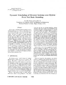
ule back to the Petri net model, the evolution of the system can be accurately simulated. Generally speaking, these strategies work quite well when the size of the Petri net is small. The hierarchical view of the above-mentioned elevator scheduling system is shown in Fig. 6. This architecture is mainly composed of three parts : a scheduler, a Petri net model, and an emulator. When a, new hall call is registered, the scheduler obtains the current status of the Petri net model and resets the control places according to the control rules and perform the scheduling. In other words, scheduler sets up the initial marking of the Petri net model by aids of control rules, and use the search method to find the suitable schedule. Once the schedule is found, the result is input into the emulator to demonstrate the scheduling result via animation. *4s the emulator performs, the firing of transitions in the Petri net model is under the control of emulator according to the scheduling result. Thus, the system is waiting for the next hall/car call reported from the physical system and then the previous process will be reported again.
ity provided by the control places. To adapt to various traffic conditions and different criteria, we can elaborately assign the necessary tokens t o the control places and guide the evolution of the Petri net model to fit our need. In other words, we can put the constraints to the Petri net by means of the control places so that the undesired firing sequence will never be enforced in the reachability graph. There are some assumptions which must be addressed before we introduce our control rules. These assumptions are listed as follows.
1) The movement of an elevator is always a series of going-up, going-down, and stopping either for waiting or for loading/unloading. An example of the trajectory of an elevator is shown in Fig. 7. 2 ) Before an elevator serves all car calls, i.e., before visiting all destinations which are registered by the riding passengers after pressing car buttons, the elevator should not reverse its direction. When an elevator is empty or stopped, it becomes free to turn t o going-up or going-down to respond t o other hall calls.
When the size of the Petri net becomes large, the reachability graph will grow rapidly so that the computer may fail to be able to generate the whole graph. Instead of generating the entire reachability graph, some heuristic rules must be employed t o generate only the necessary portion of the reachability graph. In this way, a good schedule, optimal or near optimal, can be found in a reasonable amount of time. This is extremely important especially for on-line scheduling such as the one for elevator system.
3) To predict the possible destination of a hall call, we simply assume that a passenger may traverse a third of all floors of a building. This assumption may not be reasonable because we fail to have historic data of the actual traffic pattern of a building. But the more precise prediction system is beyond the scope of this paper.
To combine the rules and Petri net model, we propose a new architecture to achieve our purpose. We use the control places mentioned previously as an interface between the rules and the Petri net model. Control places, as implied by their names, affect the possible firing sequences by the appropriate token assignment. Inevitably, there are conflicts existing in a large, complicated Petri net. Every conflict will contribute to the possibly different firing sequences in the Petri net. If a model is without any conflict, we can easily determine the best solution by simple calculation. Owing to this fact, it is clear that the solution space of the scheduling problem represented in a Petri net model is decided by the combination of all conflicts. If we can reduce the occurrences of conflicts, we can reduce the solution space efficiently and reduce the time needed for scheduling. This is one of the important reasons that we adopt the control places in our architecture. Another reason for us t o adopt them is the flexibil-
There are three categories of the control places used in the elevator Petri net model proposed here. They are ticket, reverse, and off-duty. The place tzcket is used to control the range of possible trajectory of an elevator. The place reverse is used to indicate the time when the elevator can reverse its direction without violating our assumption. And, the place off-duty is used to inform the scheduling system when the elevator will become empty. The rules to assign the tokens t o these control places are described as follows.
Rules t o assign tickets The strategy t o assign sufficient tickets is t o make every elevator be able t o pass by all hall calls. Then the best assignment is determined by the scheduler. The following are explanations of the terms to be need.
mf indicates the number of total floors in a building.
196
e
0
0
e
0
0
Rules to avoid bunching
cf indicates the current floor at which the elevator stays.
To avoid t i e bunching phenomenon in the example with four elerators in a group, the following rules are added.
dest indicates the destination of a moving elevator. If the elevator is stopped, then set dest t o cf.
1) If there are three elevator cars which are
u h indicates the highest floor among floors where up-hall calls are made and which are higher than dest.
moving upwards, the remaining elevator car should st ay in lower floors and ignore the hall calls from tlhe high floors temporarily.
dh indicates the highest floor among floors where down-hall calls are made and which are higher than dest.
2) If there zre three elevator cars which are moving dow iwards, the remaining elevator car should stay in higher floors and ignore the hall calk from the low floors temporarily.
ul indicates the lowest floor among floors where up-hall calls are made and which are lower than dest.
Besides tl-os€ rules mentioned above, we can add some particular rules for specific situation. For example, in the p2riod of incoming traffic, we can reserve one elevator rar to serve for the sparse interfloor traffic and the let the rlemaining elevator cars mainly respond to the large amount of service requests at the lobby floors, but s l i p the other hall calls t o directly return t o the lobby floor when any of them becomes empty. There are m m y similar rules which should be added t o the rulebxe to achieve better performance. However, the expansion of rulebase, even the possibility of evolving into an expert system, is beyond the scope of the current research. Among state-search algorithms, A* search is it best-first heuristic shortest-path-finding algorithm. TJsing A* search here in this paper, optimization can generally be ensured t o some extent by using an appropriate cost function. The basic heuristic search procedure together with some useful properties will be descr bed as follows. For examde, we want to search for a path from a start node s to a node g within a set of goal nodes J? ovex a graph G, which represents the search space, of thz problem. Let the sequence of nodes (s,n 1 , 7 a 2 , . . . , g) constitute a solution path. An evaluation function assigns a value to each node n in G representing a heuristic estimate for the length of the optimal soluion path constrained t o contain node n which is expressed in the following form:
dl indicates the lowest floor among floors of where down-hall calls are made which are lower than dest.
0
pred(hc)indicates the predicted destination of the hall call he. If hc is an up-hall call, pred(hc) will return m a z ( h c f m f , mf).If hc is a down-hall call, p e d ( he) will return min(he -- $mf , 1).
+
1 ) Set the variable up-dest t o the maximum among pred(uh),d h , and dest. 2 ) Set the variable down-dest to the minimum among pred(dl),ul, and dest
3) Generate all tickets for Basic Movement Module in the up direction from down-dest to up-dest and for Basic Movement Module in the down direction from up-dest to downdest.
Rules to assign reverse 1) Assign tokens t o reverse-1 and reverse-mf (as shown in Fig. 4). 2) For all floors of down hall calls down-he-i higher than floor cf and floor dest, assign token to the place reverse-i. 3) For all floors of u p hall calls up-he-i lower than floor cf and floor dest, assign token to the place reverse-i.
f ( n )= dn) + h(n) where g(n) 2 the cost from the root node s t o node n , and h ( n ) is ,i heuristic estimate of the distance from node n t o goal. It has b e m :shown that A* algorithm is complete which means that the algorithm terminates with a solution if one exists. Also, h(m)is said to be admzssrble if 0 5 h ( n ) 5 h*(m)for all successors, where h*(m)
Rules to assign ofl-dutg 1 ) Assign tokens t o place of f-duty-l off - d u t y m f (as shown in Fig. 4.)
and
2) Assign tokens to place off -duty-dest.
197
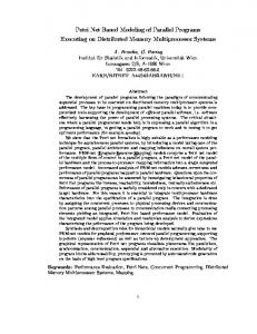
is the actual minimal cost from m t o the goal. An algorithm is said to be admissible if it is guaranteed to return an optimal solution whenever a solution exists. In practice, we can hardly guarantee that h never overestimate h* for most of the real problems. ‘4n exception is to set h nearly t o zero. But this will make the A* algorithm much more inefficient. So, there exists a useful corollary which is worthy to mention: Corollary: Graceful Decay of Admissibility If h rarely overestimates h’ by more that 6.then the A* algorithm will rarely find a solution whose cost is more than S greater than the cost of the optimal solution. In this paper, we use an example of a 15-floor building with four elevators in a group model to demonstrate the performance of proposed scheduling system. Consider the case shown in Fig. 8. In the left part of Fig. 8, the square boxes stand for the elevator cars and the circles stand for the car calls. As shown in the figure, elevator car no. 2 and 4 are stand-by on the second floor and the eighth floor, respectively, at the beginning of simulation. Elevator car no. 1 and 3 are ascending to their destination, and their current location is on the fourth floor and tenth floor, respectively, when the simulation starts. In the right part of Fig. 8, there are eight hall calls which will be progressively registered as shown in Fig. 8 within one minute from now. The upright triangles stand for the up-hall calls, the downright triangles stand for the down-hall calls, and the circles here stand for the destinations of those hall calls. These hall calls take place in time sequentially. The resulting time trajectories of the elevator cars in the simulation result responding to input hall calls are shown is Fig. 9. The waiting time for each hall call is shown in Fig. 10. The average waiting time is about 10.4 seconds. This should be an acceptable value in a general elevator system for high-rise building.
of the Petri net but also t o assign tokens, and hence the model still retain its properties and will evolve according t o the original firing rules. To obtain a schedule based on the proposed Petri net model. a heuristic search algorithm is applied. Due to the NP-complete complexity and the requirement of on-line scheduling, the control places again are used to control the transitions to be or not t o be enabled according to some constraints. By this method, some inadequate firing sequences will not be generated and the search space is efficiently reduced. To demonstrate the effectiveness of the proposed scheduling system, an experiment on a 15-floor building with four elevators were conducted and satisfactory results have been observed.
References [l] C. A . Petri, “Kommunikation mit Automaten,” Ph. D.thesis, University of Bonn, Germany, 1962.
[ 2 ] T . Murata, “Petri Nets : Properties, Analysis and Applications,” Proc. IEEE, vol. PORC-77, no. 4, pp. 541-580, Apr. 1989.
[3] R. K. Guha, S. D. Lang, M. Bassiouni, “Software Specification and Design Using Petri Nets”, Proc. of Fourth International Workshop on Software Specificatzon and Design, 1987, pp. 225-230.
[4] F. S. Etessami, G. S. Hura, “Rule-Based Design Methodology for Solving Control Problems”, IEEE Trans. on Software Engineering, vol. 17, no. 3 , 1991, pp. 274-282
[5] N. Kameli, K. Thangavelu, “Intelligent Elevator Dispatching System”, A I Expert, September 1989, pp. 32-37.
4
Conclusion
[6] H. Aoki, K. Sasaki, “Group Supervisory Control System Assisted by Artificial Intelligence”, Elevator World, February 1990, pp. 70-80.
In this paper, we proposed a systematic Petri net based modeling of an elevator group supervisory control system. The entire model is composed of a number of modules which can be classified into three types : Basic Movement Module, Loading/Unloading Module, and Direction Reversing Module. In these’ modules, control places plus a set of rules are utilized to reduce the complexity of the Petri net model. The utilization of rules on the top of a T P P N model allows the modeling t o be more accurate and much simpler. The rules are used not only t o set up the initial marking
[7] S. Tsuji, M. Amano, S. Hikita, “Application of the Expert System to Elevator GroupSupervisory Control”, IEEE 5th Conf. of Aritifical Intelligence Applications, 1989, pp. 288-294 [8] T. Tobita, H. Inaba, K. Yoneda and T. Ueshima, “An Elevator Characterized Group Superviosry Control System”, IEEE IECON’Sl, pp. 19721976
198
[91 E. Rich, K. Knight, “Artificial Intelligence”, 2nd Edition, McGraw-Hill, Inc.
Figure 6: Hierarchical Viea. for System
o
70
zc
ac
e
ID
Figure 8: Traffic Example for Simulation
,A.
.-
- ..-..
.-*mr
Figiir~4. Direction Krvarsmg Module of an Elevator
199
Figure 10: Waiting Time for Each Hall Call
S&duiirIg
w
,--