Int. J. Machining and Machinability of Materials, Vol. 11, No. 4, 2012
Process parameters optimisation and coatings influence on the surface quality during turning of AISI 202 austenitic stainless steel M. Kaladhar* Department of Mechanical Engineering, Praveenya Marine Engineering College, Modavalasa Visakhapatnam, Andhra Pradesh – 531162, India E-mail:
[email protected] *Corresponding author
K. Venkata Subbaiah and Ch. Srinivasa Rao Department of Mechanical Engineering, Andhra University, Visakhapatnam, Andhra Pradesh – 530003, India E-mail:
[email protected] E-mail:
[email protected]
K. Narayana Rao Department of Mechanical Engineering, Government Polytechnic, Visakhapatnam, Andhra Pradesh – 530003, India E-mail:
[email protected] Abstract: The aim of the present study is to investigate the effects of physical vapour deposition (PVD) and chemical vapour deposition (CVD) coated cemented carbide inserts on the surface quality of work piece. In the present work, AISI 202 austenitic stainless steel work pieces are turned on computer numerical controlled (CNC) lathe by using CVD coated insert [Ti(C, N) + Al2O3], PVD coated insert [(Ti, Al) N + TiN] of 0.4 and 0.8 mm nose radii of each. The effect of coating method and change in process parameters on the work piece surface roughness has been investigated. In order to produce any product with desired quality by machining, process parameters should be selected properly. To achieve this, the experimental investigations are executed on Taguchi’s design of experiments (DOE) approach to analyse the effect of process parameters on surface roughness and to obtain the optimal setting of these process parameters. The analysis of variance (ANOVA) is also used to analyse the influence of process parameters during turning. The results are shown that the improvement in average surface finish is obtained when machining with CVD coated insert (1.474 μm). The feed and nose radius are the most significant process parameters. Optimal range of surface roughness is also predicted. And the optimal level of parameters is obtained for optimum value surface roughness when turning with PVD and CVD insert. Keywords: PVD and CVD coated inserts; surface roughness; AISI 202 austenitic stainless steel; Taguchi’s method; analysis of variance; ANOVA. Copyright © 2012 Inderscience Enterprises Ltd.
371
372
M. Kaladhar et al. Reference to this paper should be made as follows: Kaladhar, M., Venkata Subbaiah, K., Srinivasa Rao, Ch. and Narayana Rao, K. (2012) ‘Process parameters optimisation and coatings influence on the surface quality during turning of AISI 202 austenitic stainless steel’, Int. J. Machining and Machinability of Materials, Vol. 11, No. 4, pp.371–384. Biographical notes: M. Kaladhar graduated in Mechanical Engineering from SRKR College of Engineering, Bhimavaram, affiliated by Andhra University, India in 1994 and received his Master in Industrial Engineering from College of Engineering, Trivandrum Kerala, India in 2004. He is currently working as an Assistant Professor in the Department of Mechanical Engineering in Praveenya Marine Engineering College, Visakhapatnam, India. He is pursuing his research at the Department of Mechanical Engineering, Andhra University, Visakhapatnam, India for his PhD. K. Venkata Subbaiah is a Professor of Mechanical Engineering in the College of Engineering, Andhra University, Visakhapatnam, India. Currently, he is a Honorary Director at Andhra University Development Center. He served as the Dean of Andhra University and Consulting Editor of Journal of Mechanical Engineering. He also served as a Council Member of The Institution of Engineers, India, Kolkata, and the Chairman and Honorary Secretary of The Institution of Engineers, Local Center. He has published 48 papers in various national and international journals and 23 papers in international/national conferences. He visited USA and UK. He is a fellow of Institution of Engineers (India), and a member of ISTE, ISME, ORSI, and CMSI. His areas of interests include fuzzy systems, supply chain management, inventory management and optimisation. Ch. Srinivasa Rao is currently an Associate Professor in the Department of Mechanical Engineering, Andhra University, Visakhapatnam, India. He graduated in Mechanical Engineering from SVH Engineering College, Machilipatnam, India in 1988. He received his Masters degree from MANIT, Bhopal, India in 1991. He received his PhD from Andhra University in 2004. He has published over 25 research papers in refereed journals and conference proceedings. K. Narayana Rao is a Lecturer in the Department of Mechanical Engineering, Government Polytechnic, Visakhapatnam, India. Currently, he is an Honorary Secretary in The Institution of Engineers, India, Visakhapatnam Local Center. He received the Best Teacher State award from the Department of Technical Education, Andhra Pradesh, India. He also received the Best Polytechnic Teacher award from Indian Society for Technical Education, India. He has published 20 papers in various national and international journals and ten papers in international/national conferences. He is a member of Institution of Engineers, India, and Indian Society for Technical Education, India. His areas of interests include fuzzy systems, supply chain management and optimisation.
1
Introduction
Nowadays, in machining process, surface finish is one of the most significant technical requirements of the customer. A reasonably good surface finish is desired to improve the tribological properties, fatigue strength, corrosion resistance and aesthetic appeal of the product. At present, manufacturing industries specially concerned to dimensional
Process parameters optimisation and coatings influence
373
accuracy and surface finish. In order to obtain optimal cutting parameters, manufacturing industries have depended on the use of handbook-based information which leads to decrease in productivity due to suboptimal use of machining capability leading to high manufacturing cost and low product quality (Aggarwal and Singh, 2005). Hence, the proper selection of cutting tools and process parameters plays a vital role to achieve the desired quality of surface finish. Optimisation seeks to maximise the performance of a system, part or component, while satisfying design constraints. So that, the process parameters need to be optimised to obtain the desired surface finish. Many researchers have been carried out experimental investigations over the years in order to study the effect of cutting parameters, tool geometries on the work pieces surface integrity using several work pieces. Tool geometry plays an important role in machining and the nose radius will affect the performance of the machining process (Wang and Lan, 2008). Nose radius is a major factor that affects the surface finish of work piece. It is proved that high values of nose radius causes rough surface with high value of run out (Saad Kariem, 2009). But very few researchers have studied the interaction effect of nose radius (Ravindra, 2008). The effect of nose radius on the surface roughness was investigated by Saad Kariem (2009), Ravindra (2008), Kishawy and Elbestawi (1997), Chou and Song (2004), Sundaram and Lambert (1981), Lambert (1983), and Bhattacharya et al. (1970). It was reported that austenitic stainless steels come under the category of difficult to machine materials because of their low thermal conductivity and high mechanical and micro structural sensitivity to strain and stress rate (M’Saoubi et al., 2008). Little work has been reported on the determination of optimum machining parameters when machining austenitic stainless steels (Korkut et al., 2004). Lin (2008) investigated surface roughness variations of different grades of austenitic stainless steel under different cutting conditions in high speed fine turning. Ranganathan and Senthilvalen (2009) developed a mathematical model for process parameters on hard turning of AISI 316 stainless steel. Surface roughness and tool wear was predicted by regression analysis and analysis of variance (ANOVA) theory. Xavior and Adithan (2009) determined the influence of different cutting fluids on wear and surface roughness in turning of AISI 304 austenitic stainless steel. Ciftci (2006) conducted the experiments to machine AISI 304 and AISI 316 austenitic stainless steels using chemical vapour deposition (CVD) multi-layer coated cemented carbide tools. The results showed that cutting speed significantly affected the machined surface roughness values. Cebeli et al. (2006) investigated to determine surface roughness, tool wear and tool-chip interface temperature in turning of AIS I304. Parashar et al. (2009) conducted investigation to machine wire cut electro discharge machining of 304L stainless steels to optimise surface roughness using Taguchi dynamic experiments concept. Lanjewar et al. (2008) conducted experiments to evaluate the performance of AISI 304 steel on auto sharpening machine by using Taguchi method. Results revealed that tools shape and feed are significant factors. Empirical models for tool life, surface roughness and cutting force are developed for turning of AISI 302 developed by Al-Ahmari (2007). Multiple regression analysis techniques, response surface methodology and computational neural networks were used to predict models of process functions. Kaladhar et al. (2010) determined optimum process parameters when turning of AISI 202 austenitic stainless steel. It was found that the feed is the most significant factor that influences the surface roughness followed by nose radius. A considerable work on 300 series austenitic stainless steel has been reported.
374
M. Kaladhar et al.
AISI 202 austenitic stainless steel finds it application in general industrial and process industry machinery and equipment, electrical machinery/equipment, automotive industry, structural, bus body, etc. (International Stainless Steel Forum, 2005). But, it is found that no work has been reported so far in the literature on optimisation of process parameters in turning of AISI 202 austenitic stain less steel using Taguchi approach. In the present investigation, Taguchi approach has been employed to evaluate the contribution of process parameters and determine the best combination of the process parameters such as cutting speed, feed, depth of cut and nose radius to attain the minimum surface roughness.
1.1 Taguchi approach The Taguchi method of offline quality control is considered to be an effective approach to improve product quality at a relatively low cost. The reason why design of experiments (DOE) is selected rather than the other approaches to conduct experiment is that it has a systematic planning of experiments. Taguchi technique for DOE has been the most widely used technique for the last two decades. The greatest advantage of this approach is to save the experimental time as well as the cost by finding out the significant factors. One of the important steps involved in Taguchi’s technique is selection of an orthogonal array (OA). An OA is a small set from all possibilities which helps to determine least no. of experiments which will further help to conduct experiments to determine the optimum level for each process parameters and establish the relative importance of individual process parameters. To obtain optimum process parameters setting, Taguchi proposed a statistical measure of performance called signal to noise ratio (S/N ratio). This ratio considers both the mean and the variability. In addition to S/N ratio, ANOVA is used to indicate the influence of process parameters on performance measures. Taguchi proposed three categories of performance characteristics in the analysis of the S/N ratio, that is, the smaller the better, the higher the better, and the nominal the better (Ross, 1996). Numerous researchers have been used Taguchi method to materials processing for process optimisation (Singh, 2008; Singh and Kumar, 2003; Bhattacharya et al., 2009; Barua et al., 1997; Mahapatra et al., 2006; Thamizhmanii et al., 2007; Lan, 2009). In the present work, the first criterion selects the-smaller-the better characteristic of the surface roughness.
Smaller the better type S/N ratio for Ra ,
2
[η1 ] = −10 log10 ⎡⎣ Ra2 ⎤⎦
Experiments
2.1 Work piece material The work piece material used for present work was AISI 202 austenitic stainless steel. There are two types of austenitic stainless steel: 300-series and 200-series. The 300-series type is the mostly used austenitic stainless steel around the world. The 200-series stainless steels have become popular in the Asian continent, particularly as an alternative to 300-series in view of increase in nickel prices. The 200-series are non-magnetic and austenitic. Hence, it is very difficult to distinguish 300-series of stainless steel, which are also non-magnetic. The 200-series are a technically valid family of stainless steels but,
Process parameters optimisation and coatings influence
375
like all stainless steels types they have their own limitations. The 200-series consists of manganese and nitrogen in place of nickel. The 200-series grades are generally stronger and harder than the 300-series but less corrosion resistant (Australian Stainless Steel Development Association, 2006). The chemical composition of AISI 202 is given in Table 1. Table 1
Chemical composition (wt %) of AISI 202
Cr%
Ni%
Mn%
N%
Fe%
17.0
4.0
7.5
0.25
71.5
2.2 Cutting inserts and cutting conditions About 70% of the industries are used coated cemented carbide tools. Because coated carbide tools have shown better performance when compared to the uncoated carbide tools (Noordin et al., 2004). For this reason, commonly available CVD of grade TP2500 Ti (C, N) + Al2O3 and physical vapour deposition (PVD) of grade CP200 (Ti, Al) N + TiN coated cemented carbide inserts of 0.8 and 0.4 mm as nose radius are used in the present experimental investigation. The first grade created with the DurAtomic process is TP2500. The DurAtomic technology produces chemically alter crystal structure of the aluminium-oxide (Al2O3) layer to create the coating that offers a high surface finish, less tool wear, greater tool life and speed capability. These advantages are particularly important in stainless steel machining (Seco tools). DurAtomic coating is superior to traditional coatings because of its atomic structure. The process parameters and levels used in the experiment, experimental set up and conditions are given in the Tables 2 and 3. The cutting parameters levels are selected according to the recommendations of the cutting inserts manufacturer. Table 2
Experimental set up and conditions
Machine tool
ACE designer LT-16XL CNC lathe, 7.5 kW (10 hp) and 4,000 rpm, India
Work specimen material
AISI 202 austenitic stainless steel
Size
Φ 25 mm × 70 mm
Cutting inserts
CNMG 120408, CNMG 120404 (SECO make)
Tool material
CVD coated cemented carbide (TP2500) PVD coated cemented carbide (CP200)
Tool holder
PCLNL 252570012 (ISO specification)
Environment
Dry machining
Table 3 Code
Process parameters and levels used in the experiment Process parameters
Level 1
Level 2
A
Cutting speed (m/min)
111
200
B
Depth of cut (mm)
0.25
0.75
C
Feed (mm/rev.)
0.15
0.25
D
Nose radius (mm)
0.4
0.8
376
M. Kaladhar et al.
2.3 Experimental setup and procedure Turning is a popularly used machining process in which a single point cutting tool removes unwanted material from the surface of a rotating cylindrical work piece. The computer numerical controlled (CNC) machines play a major role in modern machining industry to enhance product quality as well as productivity (Lan, 2009). The present experimental investigation was carried out according to the conditions given in table. Cutting tests were carried out on 10 hp CNC lathe machine under dry conditions. The experiments were carried out with four factors at two levels each, as shown in Table 4. Taguchi had specified L16 (215) OA experimentation. To keep the experimental design simple, two levels of factors were taken. The levels of the factors are decided on the basis of recommendations made by the tool manufacturers. The machining process on CNC lathe is programmed by speed, feed, and depth of cut. In total, 16 work pieces (Φ25 mm × 70mm) are prepared. These work pieces cleaned prior to the experiments by removing 0.5 mm thickness of the top surface from each work piece in order to eliminate any surface defects and wobbling. Two different nose radii of CVD and PVD coated inserts have been taken to study the effect of tool geometry on the surface finish of the machined work piece. The surface roughness of machined surfaces is measured by a Mitutoyo SJ-201 surface roughness tester and measurements were repeated three times. Table 4
Experimental design and responses Process parameters levels
Trial no. 1 2 3 4 5 6 7 8 9 10 11 12 13 14 15 16
3
Surface roughness Ra (μm)
A
B
C
D
When machining with CVD insert
When machining with PVD insert
1 1 1 1 1 1 1 1 2 2 2 2 2 2 2 2
1 1 1 1 2 2 2 2 1 1 1 1 2 2 2 2
1 1 2 2 1 1 2 2 1 1 2 2 1 1 2 2
1 2 1 2 1 2 1 2 1 2 1 2 1 2 1 2
1.320 0.730 2.726 1.560 1.350 0.813 2.736 1.623 1.310 0.700 1.713 1.603 1.300 0.833 1.583 1.683
2.376 1.043 4.303 2.796 2.206 1.140 4.323 2.890 2.333 0.980 4.816 2.830 2.320 1.456 4.643 2.636
Results and discussion
Experiments are conducted as per the detail given in the Tables 2 and 3. Afterwards, attempts have been made to determine the optimal range of surface roughness and
Process parameters optimisation and coatings influence
377
optimisation of process parameters. Table 4 gives experimental results. While estimating the mean and confidence interval, interaction effects are not taken in to account. Table 5
Mean values of surface roughness (Ra)
Level 1 2
PVD coated insert
CVD coated insert
Surface roughness Ra (μm)
Surface roughness Ra (μm)
A
B
C
D
A
B
C
D
2.63 5 2.75 2
2.68 5 2.70 2
1.73 2 3.65 5
3.41 5 1.97 2
1.60 7 1.34 1
1.45 8 1.49 0
1.04 5 1.90 3
1.75 5 1.19 3
3.1 Determination of predicted optimal range of surface roughness 3.1.1 When machining with PVD coated insert Performance of Ra when the two most significant factors are at their better level (based on estimated average)
μC1D2 = C1 + D2 − T = 1.732 + 1.972 − 2.693 = 1.011 (from Table 4, T = 2.693) CI ==
F95%,1, doferror *Verror nefficiency
;
where nefficiency = N/(1 + dof) of all parameters associated to that level, nefficiency = 16 / (1 + 1 + 1) = 5.333
Verror = 0.0608 (from Table 6), F95%,1,11 = 4.84 CI = 4.84*0.0608 / 5.333 = 0.0551 = 0.235
The predicted optimal range of Ra at 95% confidence level is obtained as, 1.011 − 0.235 ≤ μC1D2 ≤ 1.011 + 0.235 0.776 ≤ μC1D2 ≤ 1.246
3.1.2 When machining with CVD coated insert Performance of Ra when the two most significant factors are at their better level (based on estimated average)
μC1D2 = C1 + D2 – T = 1.045 + 1.193 − 1.474 = 0.764 (from Table 4, T = 1.474)
378
M. Kaladhar et al. nefficiency =
16 = 5.333, (1 + 1 + 1)
Verror = 0.082 (from Table 7), F95%,1,11 = 4.84 CI = 4.84*0.082 / 5.333 = 0.0744 = 0.273
The predicted optimal range at 95% confidence level is obtained as, 0.764 − 0.273 ≤ μC1D2 ≤ 0.764 + 0.273 0.491 ≤ μC1D2 ≤ 1.037
3.2 Analysis of variance The ANOVA is used to determine the optimum combination of process parameters more accurately by investigating the relative importance of process parameters (Ross, 1996). Tables 6 and 7 showed the results of ANOVA for Ra when CVD and PVD coated tools are used. It is observed that the feed (63.799%) is most significantly influences the Ra followed by nose radius (35.963%) when the work piece is turning with PVD coated tool. The feed (65.57%) is the most significant parameter followed by nose radius (28.03%) when the CVD coated tool is used. Statistically, F-test decides whether the parameters are significantly different. A larger F-value shows the greater impact on the machining performance characteristics (Ross, 1996). It is found that, feed is the most significant factor and nose radius is the second most significant factor. Table 6
ANOVA results for work piece surface roughness when machining with PVD coated tool
Source
SS
DOF
MS
F
C (%)
0.054
1
0.054
0.888
0.232
Depth of cut
0.001
1
0.001
0.0164
0.004
Feed
14.790
1
14.790
243.256
63.799
Nose radius
8.337
1
8.337
137.121
35.963
Error
0.669
11
0.0608
2.885
Total
23.182
15
Cutting speed
Table 7
ANOVA results for work piece surface roughness when machining with CVD coated tool
Source
SS
DOF
MS
F
C (%)
Cutting speed
0.284
1
0.284
3.430
6.319
Depth of cut
0.004
1
0.004
0.050
0.093
Feed
2.950
1
2.950
35.593
65.570
Nose radius
1.261
1
1.261
15.219
28.037
Error
0.912
11
0.082
20.266
Total
4.500
15
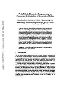
Process parameters optimisation and coatings influence Figure 1
The average surface roughness values obtained when machining with two different types of coatings (PVD and CVD)
Figure 2
The average surface roughness values obtained by machining the work piece at different values of process parameters
379
The data is given in Tables 4–7 and plots are developed with the help of a software package MINITAB 14. According to the type of coating, the lowest surface roughness was observed when the work piece is machined with CVD coated tool. The average surface roughness values obtained due to coating types is shown in box plot (Figure 1). The average surface roughness of the work piece is 1.474 μm when machining with CVD coated tool which is the lower value when compared with the value of PVD coated tool (2.693 μm). Figure 2 shows the box plot of average surface roughness values obtained by machining the work piece at different values of process parameters. It is evident that much difference of average surface roughness value is not observed at low and high
380
M. Kaladhar et al.
cutting speed. The same thing is followed in case of depth of cut parameter. The increase in feed rate from 0.15 to 0.25 mm/rev increases the average surface roughness from 1.388 μm to 2.779 μm. The tremendous improvement in the average surface roughness of 100.2% is observed that by increasing the feed rate by 66.66%. But in the case of nose radius, the increase in nose radius from 0.4 mm to 0.8 mm decreases the average surface roughness from 2.585 μm to 1.582 μm. About 39% improvements in average surface finish by decreasing the nose radius 50%. Hence, it is clear that the feed and the nose radius are the influencing parameters. Figure 3
Main effect plot for work piece surface roughness Ra when machining with PVD insert
Figure 4
Main effect plot for work piece surface roughness Ra when machining with CVD insert
Process parameters optimisation and coatings influence Figure 5
Interaction plot for work piece surface roughness Ra and process parameters when machining with PVD insert (see online version for colours)
Figure 6
Interaction plot for work piece surface roughness Ra and process parameters when machining with CVD insert (see online version for colours)
381
382
M. Kaladhar et al.
The plots show the variation of individual response with the four parameters, i.e., cutting speed, feed, depth of cut and nose radius separately. In the plots, the x-axis indicates the value of each process parameter at two level and y-axis the response value. Horizontal line indicates the mean value of the response. The main effects plots are used to determine the optimal design conditions to obtain the optimum surface finish. Figure 3 shows the main effect plot for surface roughness when machining with PVD coated tool. The results show that with the increase in cutting speed there is a slight increment in Ra value. The almost flat line shows that there is no effect due to the depth of cut. As the feed increases the surface roughness also increases. The nose radius is inversely proportional to the corresponding Ra values. Figure 4 shows the main effect plot for surface roughness when machining with CVD coated tool. It is observed that there is a decrement in the Ra with the increase in cutting speed and nose radius. In case of feed and depth of cut parameters their corresponding Ra values behave same as in the case of PVD coated tool. Figure 5 shows the interaction effects of process parameters when machining with PVD coated tool. Almost all interactions are more significant except the interaction of the feed and nose radius. It is observed that there is no interaction between those two parameters. Figure 6 illustrates the interaction effects of process parameters when machining with CVD coated tool. It is observed that the lines are parallel to each other in the plots. If the lines are parallel and not overlapping then there is little or no evidence of an interaction in the parameters. There is less interaction effect when speed interacts with feed and nose radius.
4
Conclusions
In this study, machining of AISI 202 austenitic stainless steel is carried out using PVD and CVD coated inserts of different nose radii on CNC lathe to investigate the effects of coatings on surface finish of the work piece. The Taguchi method is employed to determine the best combination of parameters cutting speed, depth of cut, feed, and nose radius to achieve the minimum surface roughness. The experimental design is planned according to the L16 OA. The ANOVA has been used to identify the influencing process parameters. The Optimal range of surface roughness of the work piece material when machining with PVD and CVD inserts is also predicted separately. From the analysis of experimental results the following conclusions are summarised: a
On comparison with PVD coated insert, the average surface roughness of the material has been decreased when machining the AISI 202 austenitic stainless steel material with CVD coated insert.
b
The relationship between feed rate and the average surface roughness is proportional. The tremendous improvement in the average surface roughness is observed that by increasing the feed rate.
c
It is observed that the there is an inverse relationship between nose radius and the average surface roughness.
d
The feed and the nose radius are most influencing parameters in overall investigation.
Process parameters optimisation and coatings influence
383
e
From the interaction plots, it is observed that there is no interaction between feed and nose radius parameters when machining with PVD and CVD insert.
f
The results of main effects plots and Table 5 indicate that a combination of low levels of cutting speed, depth of cut, feed, and high level of nose radius when machining with PVD insert, and low levels of depth of cut, feed, and high level of cutting speed, nose radius when machining with CVD insert are necessary for minimising the surface roughness of the work piece.
References Aggarwal, A. and Singh, H. (2005) ‘Optimization of machining techniques – a retrospective and literature review’, Sadhana, Vol. 30, No. 6, pp.699–711. Al-Ahmari, A.M.A. (2007) ‘Predictive machinability models for a selected hard material in turning operations’, Journal of Material Processing Technology, Vol. 190, pp.305–311. Australian Stainless Steel Development Association (2006) A Technical Bulletin 200 Series Stainless Steel CRMN Grades, Vol. 1, No. 10, pp.2–3. Barua, P.B., Kumar, P. and Gaindhar, J.L. (1997) ‘Optimal setting of process parameters for multi-characteristic products using Taguchi design and utility concept-an approach’, Proc ICAMIE, University of Roorkee, India, pp.839–842. Bhattacharya, A., Das, S., Majumdar, P. and Batish, A. (2009) ‘Estimation of the effect of cutting parameters on surface finish and power consumption during high speed machining of AISI 1045 steel using Taguchi design and ANOVA’, Production Engineering and Research Development, Vol. 3, pp.31–40. Bhattacharya, A., Faria-Gonzalez, R. and Ham, I. (1970) ‘Regression analysis for predicting surface finish and its application in the determination of optimum machining conditions’, ASME Journal of Engineering for Industry, Vol. 4, pp.711–714. Cebeli, O. et al. (2006) ‘Turning of AISI304 austenitic stainless steel’, Journal of Engineering and Natural Sciences, Vol. 2, pp.117–121. Chou, Y.K. and Song, H. (2004) ‘Tool nose radius effects on finish hard turning’, Journal of Materials Processing Technology, Vol. 148, No. 2, pp.259–268. Ciftci, I. (2006) ‘Machining of austenitic stainless steels using CVD multi-layer coated cemented carbide tools’, Tribology International, Vol. 39, No. 6, pp.565–569. International Stainless Steel Forum (2005) ‘A technical guide to chrome manganese austenitic stainless steel and advice for potential users guide’, pp.8–10. Kaladhar, M., Venkata Subbaiah, K., Srinivasa Rao, Ch. and Narayana Rao, K. (2010) ‘Optimization of process parameters in turning of AISI 202 austenitic stainless steel’, ARPN Journal of Engineering and Applied Sciences, Vol. 5, No. 9, pp.79–87. Kishawy, H.A. and Elbestawi, M.A. (1997) ‘Effect of process parameters on chip morphology’, Manufacturing Science and Technology, Vol. 6, pp.13–20. Korkut, I., Kasap, M., Ciftci, I. and Seker, U. (2004) ‘Determination of optimum cutting parameters during machining of AISI 304 austenitic stainless steel’, Materials and Design, Vol. 25, pp.303–305. Lambert, B.K. (1983) ‘Determination of metal removal rate with surface finish restriction’, Carbide and Tool Journal, Vol. 23, pp.16–19. Lan, T-S. (2009) ‘Taguchi optimization of multi objective CNC machining using TOPSIS’, International Technology Journal, Vol. 8, No. 6, pp.917–922. Lanjewar, R.W., Saha, P., Datta, U., Bemire, A.J., Jian, S. and Sen, S. (2008) ‘Evaluation of machining parameters of AISI304 austenitic stainless steel on auto sharpening machine’, Journal of Scientific Industrial and Research, Vol. 67, pp.282–287.
384
M. Kaladhar et al.
Lin, W.S. (2008) ‘The study of high speed fine turning of austenitic stainless steel’, Journal of Achievements in Materials and Manufacturing, Vol. 27, No. 2, pp.10–12. M’saoubi, R. et al. (2008) ‘A review of surface integrity in machining and its impact on functional performance and life of machined products’, International Journal of Sustainable Manufacturing, Vol. 1, Nos. 1/2, pp.203–236. Mahapatra, S.S. et al. (2006) ‘Parametric analysis and optimization of cutting parameters for turning operations based on Taguchi method’, Proceedings of the International Conference on Global Manufacturing and Innovation, Coimbatore, India, pp.1–8. Noordin, M.Y., Venkatesh, V.C., Sharif, S., Elting, S. and Abdullah, A. (2004) ‘Application of response surface methodology in describing the performance of coated carbide tools when turning AISI 1045 steel’, Journal of Materials Processing Technology, Vol. 145, pp.46–58. Parashar, V., Rehman, R., Bhagoria, J.L. and Puri, Y.M. (2009) ‘Investigation and optimization of surface roughness for wire cut electro discharge machining of SS 304L using Taguchi dynamic experiments’, International Journal of Engineering, Vol. 1, pp.257–267. Ranganathan, S. and Senthilvalen, T. (2009) ‘Mathematical modeling of process parameters on hard turning of AISI316 SS by WC insert’, Journal of Scientific Industrial and Research, Vol. 68, pp.592–599. Ravindra, T. (2008) ‘Comparison between multiple regression models to study effect of turning parameters on the surface roughness’, Proceedings of the 2008 IAJC-IJME International Conference, USA, pp.1–12. Ross, P.J. (1996) Taguchi Techniques for Quality Engineering, McGraw-Hill Book Company, New York. Saad Kariem, S. (2009) ‘Studying the effect of tool nose radius on work piece run out and surface finish’, Engineering and Technology Journal, Vol. 27, No. 2, pp.256–261. Singh, H. (2008) ‘Optimizing tool life of carbide inserts for turned parts using Taguchi’s design of experiment approach’, Proceedings of International Multi Conference of Engineering and Computer Scientists, Hong Kong, pp.19–21. Singh, H. and Kumar, P. (2003) Quality Optimization of Turned Parts (En 24 Steel) by Taguchi Method. Productivity Journal, Vol. 44, No. 1, pp.43–48. Sundaram, R.M. and Lambert, B.K. (1981) ‘Mathematical models to predict surface finish in the fine turning of steel’, International Journal of Production Research, Vol. 19, pp.547–564. Thamizhmanii, S., Saparudin, S. and Hasan, S. (2007) ‘Analyses of surface roughness by turning process using Taguchi method’, Journal of Achievements in Materials and Manufacturing, Vol. 20, No. 2, pp.503–506. Wang, M.Y. and Lan, T.S. (2008) ‘Parametric optimization on multi objective precision turning using grey relational analysis’, International Technology Journal, Vol. 7,pp.1072–1076. Xavior, A. and Adithan, M. (2009) ‘Determining the influence of cutting fluids on tool wear and surface roughness during turning of AISI 304 austenitic stainless steel’, Journal of Material Processing Technology, Vol. 209, pp.900–909.
Websites http://www.secotools.com