PROC. SPIE, 3591, 63-70 (1999)
Pupil-meter and tracking system based in a fast image processing algorithm Ignacio Miró*1,2 Norberto López-Gil1 and Pablo Artal1 1
Laboratorio de Óptica, Universidad de Murcia. Campus del Espinardo (Edificio C), 30071 Murcia, Spain. 2 Dep. Ingeniería Electrónica, E.P.S. de Alcoy, Universidad Politécnica de Valencia. Plaza de Ferrándiz y Carbonell, 1 - 03801 Alcoy, Spain ABSTRACT A low cost pupil-meter and tracking apparatus was developed. It is based in digital analysis of images of the anterior eye to measure the diameter of the eye pupil and to track the position of its geometrical center at video rate. The system consists in an array of infrared LEDs to illuminate the eye and a CCD video camera that captures the images of the pupil to be grabbed in a computer. A fast algorithm analyses the digital images (512x512 pixels) in real time (25 images per second) providing the pupil diameter and the location of the geometrical center within that temporal rate. The algorithm was implemented to run under DOS, Win 3.x or Win95 and is compatible with any frame-grabber. The reliability of the apparatus was tested in different subjects for the particular problems of measuring the pupil diameter during accommodation and tracking the eye position during fixation. Under the measuring range, the system is robust to moderate lateral and axial movements of the subject. The spatial resolution is 0.02 mm and the linearity in measuring the pupil diameter is better than 1% in the complete useful range. The apparatus was adapted to operate without interfering either the visual task or possible simultaneous measurements. Keywords: pupilometry, digital image processing, eye tracking.
1. INTRODUCTION The size of the human pupil is an important parameter in different studies in Vision and Ophthalmology as well as in other areas such as Psychology, Psychiatry, Publicity, etc. The pupil controls the amount of light reaching the retina behaving as a negative feedback servomechanism1 by decreasing the pupil size when the irradiance that reaches the eye increases, and vice versa. From an optical point of view, the pupil plays an important role on the retinal image quality due to the relation between the monochromatic aberrations and the spatial cut-off frequency transferred with the pupil radius. Most of current pupil-meters are based on the Green and Maaseidvaag closed-circuit television version2, incorporating new characteristics and improving the performances3-5. In this paper we present a new version of a pupil-meter. It is a relatively low-cost system operating in real time (25 images per second) under MS Windows and providing both, the pupil size, and the position of the geometrical pupil center.
2. MATERIAL AND METHODS The pupil-meter is based on the real time digital image processing of the images of the pupil. The system consists basically on an array of infrared LED’s (iLED) for pupil illumination, and a b/n CCD video-camera (Sony XC 75-CE), with manual gain mode. The images captured by the camera (768(H) x 494(V) pixels) are transferred to a frame grabber (Matrox Magic). Near infrared light (950 nm) was used for illumination because it does not affect the pupil size. Another advantage on using this wavelength is that the iris presents a higher reflection factor so increasing the contrast of the images.
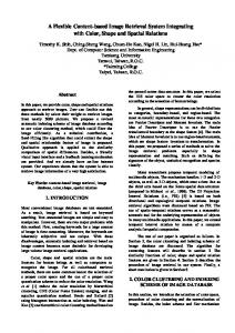
The system is versatile and can be implemented to be used in different backgrounds. In Fig. 1 it has been represented schematically the set-up built for the measurement of the change of the pupil size and position under different conditions of interest in Physiological Optics.
High resolution monitor
PC
Screen
CCD
L2
L3
L1
F’2 F3
Stimulus for accommodation
DM iLED
5D
0D
Figure 1. Experimental set-up (see text for details).
The experimental set-up in Fig. 1 incorporated two auxiliary monitors, one connected to the output of the CCD camera, and a second connected to the VGA output of the frame grabber. The two monitors show the pupil image and the content of the frame grabber memory, respectively. The image processing is carried out by using the functions of the library of the frame grabber managed by a program written in C. The software also provides the possibility of recording data of the measurement as well as single pupil images. In order to perform a study of the change of the pupil diameter as a function of the accommodation (accommodative miosis) we have included in the set-up three lenses L1, L2 and L3, with the same focal length (190 mm) aligned with the eye. L1 and L3 are fixed and L2 can be moved along the optical axis originating an apparent displacement of the stimulus respect to the subject while keeping unchanged the angle under it can be seen. If the position of the lens L2 is such that its focal image (F´2) matches with the focal object of the lens L3 (F3), as it is the case of Fig. 1, the stimulus seems to be placed at the infinite for the subject. Now, if the lens L2 moves towards the subject, the rays that emerge from the lens L3 will not arrive parallel to him/her but divergent, so the subject has to accommodate in order to keep seeing the object clear. The accommodation, in diopters, is the inverse of the distance, in meters, between the apparent position of the stimulus and the observer (neglecting accommodative errors6). Then, an accommodation of 0 D is originated for a stimulus placed apparently at the infinite while if it is located at 20 cm the accommodation induced would be 5 D. To be able to obtain clear images of the pupil on the camera with the objective focusing to the infinite, the distance between the pupil of the observer and the lens L3 should be equals to the focal length of the lens L3. The dichroic mirror, DM, transmits the visible light of the stimulus but reflects the near infrared light of the iLEDs used for pupil illumination. Part of the infrared light that reaches the eye is reflected in the surfaces of the cornea and lens producing Purkinje images that could hide the detection of the shape of the pupil. Figure 2 shows the gray level of a horizontal section of the image of the pupil with the first Purkinje image of a single iLED.
250 Purkinje image
grey level
200 iris
150
iris
100
pupil
50 0 0
100
200
300
X axis
400
500
Figure 2. Luminance profile of a horizontal section of an image. Arrows show the points located by the algorithm corresponding to pupil edges and middle point.
To avoid a possible error that a Purkinje image could cause when detecting the pupil edges, the array of iLEDs is placed so that the Purkinje images are located outside of the area of study (see Fig. 4 bellow). Assuming the pupil to be circle, the parameter used to calculate the pupil size is the length of the vertical segment defined by the highest and lowest edges of the pupil. The algorithm detects the pupil edges considering the evolution of the luminance of the image. Figure 3 shows the edge detection procedure that consists on a double sweep of the image profile. Starting at any point inside the pupil (Fig. 3 A), the first sweep, horizontal (Fig. 3 B), serves to find the left and right pupil edges. Then the middle point of the horizontal segment is located (Fig. 3 C). The second sweep, vertical (Fig 3 D), determines the length of the vertical segment which ends at the highest and lowest pupil edges and pass through the middle point between the left and right edges located in the first sweep (Fig. 3 E). Finally the geometric center of the pupil is located as the middle point of the vertical segment. A
B
C
1
D
E
2 Figure 3. Pupil diameter detection procedure.
A procedure like the one showed in Fig. 3 allow us to use the system without the need of a dichroic mirror as showed in Fig.1. We can place the camera off-axis in the horizontal plane to obtain a direct image of the pupil. The image in this case would be an ellipsoid (instead a circle) which height would correspond to the actual pupil diameter.
During the recording time the processed image is shown in the high-resolution monitor with three marks (corresponding to the edges and middle points) at the four study areas (see Fig. 4). This helps the operator to check that the measures are being carried out correctly.
Figure 4. Image of the eye’s pupil showed by the high-resolution monitor. Each set of three points represents the estimate of the iris edges and its middle point. The central point shows the geometrical center of the pupil. Distance between the middle points of the highest and lowest sets represents the actual pupil size.
Figure 5 shows, as an example, the pupil diameter in one subject during approximately a half of a minute.
6
Pupil size (mm)
5 4 3 2 1 0 0
5
10
15
20
25
30
Time (s) Figure 5. Pupil size (diameter) as a function of time. The discontinuities represent observer's involuntary blinks.
In all the experiment carried out the subjects used a bite bar to fix their head although it is not necessary for pupil size measurements. Depending on the experiment, five or less observers between 25 and 30 years participated. The intensity of the near infrared light used for illumination was well below the safety standards. The stimulus for accommodation consists on a group of letters similar to those used in the ophthalmologic exams. Measuring the diameter of circular apertures of known sizes carried out the calibration of the system. The spatial resolution obtained was 0.02 mm/pixel and the error in the linearity is less than 1%.
3. RESULTS In this section some examples of application are presented.
3.1. Accommodative miosis Five subjects have been involved in this experience. For each of them, it have been carried out a set of three measurements of the pupil size from 5 to 10 s in six different states of accommodation (0, 1, 2, 3, 4, and 5 D). Figure 6 represents the average of each set of measurements. The results show a decrease in the subject’s pupil diameter as the object approaches (accommodative miosis) being this decrease very dependent on the subject.
Pupil size (mm)
8 7 6 5
Subject A Subject B Subject C Subject D Subject E
4 3 0
1
2
3
4
5
Accommodation (D) Figure 6. Pupil size versus accommodation in five subjects.
3.2. Eye tracking As it has been mentioned before, the algorithm also provides the position of the geometric center of the pupil in real time (25 Hz). In the next, we present two examples of its potential application. First, we evaluated the movement of a pupil when fixating to a point (fixation example). Second, we tracked the eye when the subject changes his/her direction of gaze between different letters ordered in a circle (reading example). It is important here to point out that the direction of gaze is commonly obtained by using the information of the Purkinje images and the pupil center. In our case, we have only used the pupil center data because errors originated by eye translations instead rotations are not possible due to the fixation of the subject’s head.
3.2.1. Fixation example With the stimulus placed apparently at the infinite, the subject is said to fixate to the center of the stimulus and to try to gaze the same point during the recording time (about 15 s). We performed a set of three measurements in two subjects. Once the data is obtained, we calculated the average coordinates of the pupil center during the whole recording time and used this point as origin of coordinates. Figure 7 shows the results of one of the measurements in one subject.
80 60
Angle (arcmin)
40 20 0 -80
-60
-40
-20
0
20
40
60
-20 -40 -60 -80 Angle (arcmin)
Figure 7. Direction of gaze of a subject who look at a fixed point during 15 s.
We have also calculated from the set of data showed in Fig. 7 the angle from the pupil center respect to the origin of coordinates as a function of time (not shown). The results revealed that for this subject, the maximum angle that the direction of gaze is displaced respect to the origin of coordinates is 100 arcmin, probably due a saccadic movement. The average displacement found during the recording time showed in Fig. 7 was 26 arcmin which is in good agreement with the values showed in the bibliography7.
3.2.2. Tracking example We have taken another set of measurements of eye tracking when the subject read a group of letters in a circle. Figure 8 shows an example. We used in this case the same set-up showed in Fig. 5 but the test was placed at 19 cm from the subject and had a diameter of 3 cm.
After Fig. 8, it is clear that the system is able to track the direction of gaze correctly and knowing that the first letter looked at was G, the subject read the others letters in unclockwhise sense finishing at the letter J.
H O
R
Y
Z Y
J G
Figure 8. Direction of gaze of a subject looking at a set of letters.
4. CONCLUSIONS We have developed a system that is able to measure the human pupil size by processing images of 512x512 pixels in real time (25 images per second). Its spatial resolution is 0.02 mm/pixel and the error in the linearity is less than 1%. The software allows us to storage images of the pupil, to have the control of an external stimulus, and to visualize the direction of gaze, among others. The pupil-meter presented is then sufficiently robust and its temporary and space resolution performances are acceptable for most of applications. In comparison with other systems that depend on the hardware, this system could be connected to any kind of frame grabber or operative system because the algorithm code is simple and portable. The software developed could also be used in other pupil-meter systems as well as in head-up devices. As examples, we have applied the system to measure the change of pupil size pupil as a function of the accommodation. By measuring the change of the visual direction of gaze when the subject looks at a fixed point or when he/she reads a group of letters it has been has also possible test the tracking function. The performances of the system make it especially applicable to tasks related with the research in Physiological Optics and Ophthalmology. It should be noticed, however, that the system depends on the conditions of illumination and the quality of the images, so it requires a quite homogeneous illumination in the whole surface of the eye. It is also desired to have a constant illumination during the measurement time.
ACKNOWLEDGEMENTS This research was supported by the Dirección General de Enseñanza Superior (DGES), Spain, grant nº PB97-1056.
REFERENCES 1. L. Stark, F.W. Campbell, & J. Atwood. "Pupil unrest: An example of noise in a biological servomechanism". Nature 182, 857 (1958). 2. D. G. Green & F. Maaseidvaag. "Closed-circuit Television Pupillometer". J.Opt.Soc.Am. 57, 830-833, 1967. 3. T. Watanabe, M. Ikeda, T. Suzuki & F. Nakamura. "Infrared television pupillometer revised: Bright-pupil illumination and computer automation". Rev.Sci.Instrum. 61, 36-41, 1991. 4. Natan Roizin & Yacov Roizin. "Image processing in computer pupillography". Proc S.P.I.E. Vol. 1647, 49-53, 1992. 5. W. J. McLean & R. C. Frecker. "Clinical Pupillometry system running under MS-Windows". Inves.Ophtal.Vis.Sci. (Suppl.), 33, 1146, 1992.
6. N. López-Gil, I. Iglesias & P. Artal, “Retinal image quality in the human eye as a function of the accommodation”. Vis. Res., 38, 2897-2907, 1998. 7.
*
R.H.S. Carpenter, Movements of the Eye. Pion Press, 1988.
Correspondence: Email:
[email protected]; http://lo.um.es; Tel: 34-968367222; Fax: 34-968363528.