I. INTRODUCTION
Radon-Fourier Transform for Radar Target Detection, I: Generalized Doppler Filter Bank JIA XU, Member, IEEE Air Force Radar Academy, Wuhan JI YU YING-NING PENG, Senior Member, IEEE Tsinghua University XIANG-GEN XIA, Fellow, IEEE University of Delaware Based on the coupling relationship among radial velocity, range walk, and Doppler frequency of the moving target’s echoes, a novel method is proposed, i.e., Radon-Fourier transform (RFT), to realize the long-time coherent integration for radar target detection. The RFT realizes the echoes spatial-temporal decoupling via joint searching along range and velocity directions, as well as the successive coherent integration via the Doppler filter bank. Besides, four equivalent RFTs are obtained with respect to the different searching parameters. Furthermore, a generalized form of RFT, i.e., generalized Radon-Fourier transform (GRFT), is also defined for target detection with arbitrary parameterized motion. Due to the similarity between the RFT and the well-known moving target detection (MTD) method, this paper provides detailed comparisons between them on five aspects, i.e., coherent integration time, filter bank structure, blind speed response, detection performance, and computational complexity. It is shown that MTD is actually a special case of RFT and RFT is a kind of generalized Doppler filter bank processing for targets with across range unit (ARU) range walk. Finally, numerical experiments are provided to demonstrate the equivalence among four kinds of RFTs. Also, it is shown that the RFT may obtain the coherent integration gain in the different noisy background and the target’s blind speed effect may be effectively suppressed. In the meantime, both the weak target detection performance and the radar coverage of high-speed targets may be significantly improved via RFT without change of the radar hardware system. Manuscript received February 27, 2009; revised October 3, 2009; released for publication December 29, 2009. IEEE Log No. T-AES/47/2/940838. Refereeing of this contribution was handled by C. Baker. This work was supported in part by China National Science Foundation under Grant 60971087, China Ministry Research Foundation under Grant 9140A07051208JW0111 and 9140C130510D246, Aerospace Supporting Foundation under Grant J04-2007047, China Aerospace Innovation Fund under Grant CASC 200904, and China Aviation Science Foundation under Grant 20080158001. X-G. Xia’s work was supported in part by a DEPSCoR Grant W911NF-07-1-0422. Authors’ addresses: J. Yu, and Y-N. Peng, Section of Signal Detection, Dept. of Electronic Engineering, Tsinghua University, Beijing, 100084, P.R. China; J. Xu, Air Force Radar Academy, Wuhan, 430019, P.R. China, E-mail: (
[email protected]); X-G. Xia, Dept. of Electrical and Computer Engineering, University of Delaware, Newark, DE 19716. c 2011 IEEE 0018-9251/11/$26.00 ° 1186
It is known that pulse integration is an effective method to improve radar target detection performance in a noisy background, while the coherent integration may obtain better performance than the incoherent integration by compensating phase fluctuation among different sampling pulses [1—8]. For example, the well-known moving target detection (MTD) [1—2] method has been widely applied by modern coherent radar, where Doppler filter bank processing is used for the effective suppression of strong background clutter, as well as for the coherent integration of a moving target with unknown Doppler frequency. Besides, the MTD may be efficiently implemented via fast Fourier transform (FFT). Unfortunately, the MTD input vectors are the pulse samplings distributed along range units one-by-one and the performance gain is limited by the target’s resident time in a single range unit. As a result, it is difficult to further improve the performance via MTD for the low signal-to-noise (SNR) target or the high-speed target [3—4]. For the low SNR target, e.g., far-range or low radar cross section (RCS) target, the integration time should be adequately enlarged and the range walk, i.e., the linearly varied distance between target and radar, of even a slowly moving target will exceed several range units. For a high-speed target, this kind of across range unit (ARU) effect may also be drawn even in a very short integration time. Furthermore, with the remarkably refined range resolution of modern radar, it becomes necessary to deal with the ARU effect of moving targets. In this regard, Perry, et al. [9—10] and Zhang, et al. [11] have introduced the Keystone transform (KT) for synthetic aperture radar (SAR) ground moving targets imaging and weak radar target detection via long-time coherent integration. KT may blindly compensate the ARU effect and not destroy the pulse phase modulation. So MTD may be used for the successive coherent integration after KT. However, the existing radar, especially the searching radar, normally adopts the low pulse repetition frequency (PRF) to guarantee the far-range target detection. Therefore, most air targets may be Doppler ambiguous, for which KT may be invalidated without ambiguity correction. Yang, et al. [12] have proposed a modified KT method via simultaneous searching of the Doppler ambiguous integers and frequency, but it needs repeated implementations of high-complexity KT operators. Another more natural method is to realize the successive Doppler matching after compensation of the target’s unknown range walk. Reed, et al. [13] have proposed a coherent integration method for MTD of optical image sequence. However, this method needs a 3-dimensional matched filtering, which is not realistic for radar target detection. Wang, et al. [14] have proposed an envelope compensation method
IEEE TRANSACTIONS ON AEROSPACE AND ELECTRONIC SYSTEMS VOL. 47, NO. 2 APRIL 2011
based on range stretching and time-frequency analysis, which is applicable to the time-varied Doppler case but is also computational complicated. Chen, et al. [15, 16] proposed a method to realize the echo envelopes’ shifting compensation by searching the target speed and accomplish the coherent integration by using the FFT-based Doppler filter bank. However, the coupling relationship between velocity and Doppler of moving target is not exploited and its FFT-based Doppler filter bank processing seems to be abundant. Also, there are other researchers who have proposed to adopt the incoherent integration, or the hybrid coherent-incoherent method to improve the weak target detection performance. Along this direction, the typical works may be the Hough transform (HT) based method proposed by Carlson, et al. [17—22]. The HT is used to inherently integrate the target slots exceeding the first low decision threshold, which may remarkably suppress false alarms and improve the ultimate detection performance. Furthermore, Mo, et al. [22] have also proposed an HT-based long-time integration method, which transforms the radar raw data into range-Doppler-time space and realizes the high-performance detection for targets with constant velocity or acceleration. However, without compensation of the phase fluctuation, the integration loss of the HT-based method may be large compared with a coherent integration method and it thus may not be applied when the SNR is extremely low. Based on the signal model of a rectilinearly moving target in a long-time integration, this paper proposes a novel Radon-Fourier transform (RFT) to realize the long-time coherent integration for the moving targets with ARU range walk. Different from the existing Radon or Fourier transform methods [26, 27], RFT can effectively overcome the coupling between the range walk and phase modulations by jointly searching along range and velocity directions of moving targets. Furthermore, the Doppler filtering is also used for the successive long-time coherent integration. With different searching parameters, four equivalent continuous RFT forms are obtained. Then, the parameter space of RFTs is analyzed and discrete RFTs are also derived. Furthermore, a generalized form of RFT, called generalized RFT (GRFT), is defined for radar target detection with arbitrarily parameterized motions. Due to the similarity between the RFT and the existing MTD methods, this paper provides comparisons between them on five aspects, i.e., coherent integration time, filter bank structure, blind speed response, detection performance, and computational complexity. It is shown that the MTD is a special case of RFT method, and the RFT method is a generalized Doppler filter bank processing. Finally, some numerical experiments are provided to show that the RFT may obtain the coherent integration
gain in the different SNR background and the blind speed may also be effectively suppressed. In the meantime, both the weak target detection performance and the radar coverage of high-speed target may be significantly improved via RFT without change of the radar hardware system. The remainder of this paper is organized as follows. In Section II the long-time integration signal model is established. In Section III we introduce the continuous RFTs. In Section IV RFT parameter design is discussed. In Section V four equivalent discrete RFTs are derived. In Section VI RFT and MTD are compared. In Section VII some numerical experiments are provided. In Section VIII conclusions are given. II.
SIGNAL MODELING FOR RADAR TARGET IN A LONG-TIME COHERENT INTEGRATION
Suppose linear frequency modulated (LFM) signal is used by radar transmitting, i.e., sT = rect(¿ =Tp ) exp(j¼°¿ 2 )
(1)
where Tp is the pulse duration, ° is the frequency rate of LFM signal, Bs = °Tp is the signal bandwidth. Furthermore, suppose there is a moving target with slant range RT and radial velocity vT at t = 0, then the target’s range walk may be given as rˆ (t) = RT + vT t,
t 2 [¡T=2, T=2]:
(2)
Normally, the target’s high-order motions, e.g., acceleration, tangential motion, and so on, may exist in real targets. Fortunately, their effects on our proposed method will be reasonably controlled via limiting the coherent integration time T as discussed as Section IVA. Accordingly, the two-dimensional echoes may be represented as à ! ¿ ¡ 2rˆ (t)=c exp(j¼°(¿ ¡ 2rˆ (t)=c)2 ) sr (t, ¿ ) = Ar rect Tp μ ¶ 4¼rˆ (t) £ exp ¡j , t 2 [¡T=2, T=2] (3) ¸ where ¿ is quick-time, ¸ is the wavelength, c is the light speed, and Ar is the complex amplitude of the echo. After the pulse compression, the target’s 2D echoes may be given as μ ¶ 4¼ rˆ (t) srm (t, ¿ ) = Arm sinc(¼Bs (¿ ¡ 2rˆ (t)=c)) exp ¡j , ¸ t 2 [¡T=2, T=2]
(4)
t 2 [¡T=2, T=2]:
(5)
where Ar,m = Tp BAr . With rˆ = c¿ =2,(4) may be further rewritten as μ ¶ μ ¶ 2¼Bs (rˆ ¡ rˆ (t)) 4¼rˆ (t) exp ¡j , srm (t, rˆ ) = Arm sinc c ¸
XU ET AL.: RADON-FOURIER TRANSFORM FOR RADAR TARGET DETECTION, PART I
1187
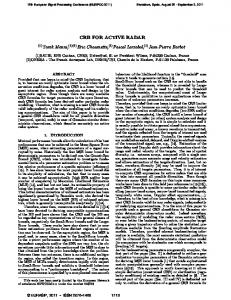
Fig. 1. Data extraction for RFT processing. (a) ½ > 0, μ 2 [0, ¼=2] (v < 0, rsT > 0). (b) ½ > 0, μ 2 (¼=2, ¼] (v > 0, rsT > 0):
Moreover,with a pre-set scene range center rˆc , rˆ (t) may be represented as rˆ (t) = (RT ¡ rˆc ) + rˆc + vT t = rsT + rˆc + vT t
(6)
where the initial relative range rsT = RT ¡ rˆc . Define rs = rˆ ¡ rˆc the relative range and substituting (6) into (5), we have μ ¶ ¼(rs ¡ rs (t)) exp(j2¼fdT t), srm (t, rs ) = AT sinc ½r t 2 [¡T=2, T=2]
(7)
where rs (t) = rsT + vT t, ½r = c=2Bs is the range resolution, and AT = Arm exp(¡j4¼(rsT + rˆc )=¸) is a complex backscattering coefficient. In real applications, AT may fluctuate and bring about phase noise for coherent integration [6, 7]. In this paper AT is assumed to be a constant for simplicity as in many existing literatures [1—5, 8—22], and the target’s Doppler is also defined as fdT = ¡2vT =¸:
(8)
Then, we introduce a kind of special integration on srm (t, rs ) in (7) as Z 1 Z T=2 G½μ (½T , μT ) = srm (t, rs ) ¡1
¡T=2
£ ±(½T ¡ t cos μT ¡ rs sin μT )HμT (t)dt drs = AT T:
¡1
(13)
¡T=2
£ ±(½T ¡ t cos μT ¡ rs sin μT )dt drs Z T=2 = srm (t, rs (t))dt: (14)
III. CONTINUOUS RFT AND LONG-TIME COHERENT INTEGRATION From Fig. 1(a)—(b), it is shown that the target’s range walk curve in the t ¡ rs plane may also be determined by another parameter pair (½T , μT ), where polar angle μT 2 [0, ¼] is defined as the anticlockwise angle from the range walk line to t-axis as
1188
Furthermore, based on the mutual relationship between the radial velocity and rs (t) of moving target, a pair of Doppler filter functions HvT (t) and HμT (t) are define as μ ¶ 2vT HvT (t) = exp j2¼ t = exp(¡j2¼fdT t) (11) ¸ μ ¶ 4¼ctg(μT )t HμT (t) = exp ¡j : (12) ¸
It is shown that all the echoes in the integration time may be coherently integrated via (13). For comparison, we also give the Radon transform (RT) [23, 24] of srm (t, rs ) as Z 1 Z T=2 srm (t, rs ) R½μ (½T , μT ) =
From (6) and (7), it is shown that the range-compressed echoes of the moving target are approximately distributed along a straight line in the t ¡ rs plane, and Fig. 1(a)—(b) further give two cases with positive and negative radial velocities v, respectively.
μT = ctg¡1 (¡vT ):
Also, polar distance ½T 2 (¡1, +1) is defined as the minimum distance between the range walk and the t ¡ rs plane origin as ½T = rsT sin μT : (10)
(9)
¡T=2
Obviously, we have jG½μ (½T , μT )j ¸ jR½μ (½T , μT )j due to the uncompensated phase changes among different pulses for (14). In real applications, because parameters rT and vT , as well as ½T and μT , are all unknown before target detection and parameter estimation, all the possible polar angles and polar
IEEE TRANSACTIONS ON AEROSPACE AND ELECTRONIC SYSTEMS VOL. 47, NO. 2 APRIL 2011
distances should be searched, that is Z T=2 ³ ½ ´ srm t, ¡ t ctgμ Hμ (t)dt, G½μ (½, μ) = sin μ ¡T=2 ½ 2 [¡1, 1],
μ 2 [0, ¼]
(15)
where μ and ½ are the searching variables for polar angle and polar distance, respectively. From (9), (15) can also be rewritten as Z T=2 ´ ³ p G½v (½, v) = srm t, ½ 1 + v2 + vt Hv (t)dt, ¡T=2
½ 2 [¡1, 1],
v 2 [¡1, 1]
(16)
where v is a searching velocity. Similarly, (15) can also be rewritten as Z T=2 Grμ (r, μ) = srm (t, r ¡ t ctgμ)Hμ (t)dt, ¡T=2
Grv (r, v) =
Z
r 2 [¡1, 1],
μ 2 [0, ¼]
(17)
T=2 ¡T=2
srm (t, r + vt)Hv (t)dt,
r 2 [¡1, 1],
v 2 [¡1, 1]
(18)
where r is a searching variable for slant range along the rs -axis. By using (15)—(18), the coherent integration outputs can be obtained with respect to the different searching parameter pairs. Only when the searching range (or polar distance) and radial velocity (or polar angle) are equal to the rsT (or ½T ) and vT (or μT ), the target energy distributed along multiple pulses can be coherently integrated. In other words, for the same echoes, (15)—(18) will all generate the equivalent matched “peaks,” respectively. Besides, the parameters of (½T , μT ), (½T , vT ), (rsT , μT ), and (rsT , vT ) can be interchanged based on (9) and (10). Interestingly, (15)—(18) have the similar parts as RT or the Hough transforms (HT) [23, 24] with the additional Fourier integration component. Thus, we call (15)—(18) as RFT in this paper. Without loss of generality, the definition of RFT may be given as follows. DEFINITION 1 Suppose a 2-D complex function f(t, rs ) 2 C is defined in (t, rs ) plane and a parameterized line equation rs = '(®1 , ®2 ) + Á(®1 , ®2 )t is used for searching arbitrarily lines in the plane, where '( ) and Á( ) are two specific functions to determine a line with parameters ®R1 and ®2 , then the 1 RFT is defined as G®1 ®2 (®1 , ®2 ) = ¡1 f(t, '(®1 , ®2 ) + Á(®1 , ®2 )t) exp(j2¼"Á(®1 , ®2 )t)dt, where " is a known constant with respect to f(t, rs ). Specifically, when the line equation rs = r + vt is used, the transform R1 Grv (r, v) = ¡1 f(t, r + vt) exp(j2¼"vt)dt is called “standard RFT” due to the explicit meaning of parameter r and v. By comparing the definitions of RFT and the existing RT or HT, e.g., (14) [23, 24], there are some
important differences among them, three of which are given as follows. 1) The existing RT and HT, especially HT, are normally defined in the real image domain regardless of coherent integration of the phase information, which are normally used to enforce the special geometry structures, e.g., line, curve, or surface, in the image by exploiting the correlation on the signal’s amplitude. The proposed (15)—(18) are defined in the complex signal domain, which jointly exploits the amplitude and phase information. 2) For the integration transforms as (15)—(18), the important Doppler compensation functions Hv (t) or Hμ (t) are introduced to act as a Fourier integration component, which cancels the phase fluctuations among different pulses and generates the ultimate coherent “peak.” The introduction of these operators is the main differences between the proposed method and the existing HT or RT methods. In this sense, the RFT is applying Fourier integration along a line with a certain direction, which is determined via the RT. In Section VI, it is proven that RFT has similar effects as the conventional Doppler filter bank, e.g., the MTD method, but it will significantly outperform the MTD via a relatively long integration time. 3) In (16)—(18) the slant range r or radial velocity v is involved, which all have clear physical meaning in radar signal processing, while the transform parameters of conventional RT or HT normally only have the geometry structure meanings but no explicit physical meaning or background. Furthermore, based on the proposed RFT as (15)—(18), we further give a more generalized long-time coherent integration method, i.e., GRFT, for radar MTD with any parameterized motion as follows. DEFINITION 2 Suppose a 2-D complex function f(t, rs ) 2 C is defined in (t, rs ) plane and a parameterized N + 1 dimensional equation rs = ´(®1 , : : : , ®N , t) is used for a certain time-varied in the plane, then the GRFT is G(®1 , : : : , ®N ) = Rcurve 1 f(t, ´(®1 , : : : , ®N , t)) exp(2¼"´(®1 , : : : , ®N , t))dt ¡1 where " is a known constant with respect to f(t, rs ). Why do we call the proposed method GRFT? R1 The reason is that the part ¡1 f(t, ´(®1 , : : : , ®N , t))dt in the GRFT may be regarded as a generalized RT along a parameterized curve and the part exp(2¼c´(®1 , : : : , ®N , t)) in the GRFT actually acts as a phase compensation component for coherent integration. Obviously, the RFT in Definition 1 is a special case of GRFT when the searching parameterized curve is degenerated into a line and the certain phase exp(j2¼"'(®1 , ®2 )) is omitted for simplicity. More importantly, by using the proposed GRFT processing, coherent radar’s moving target echoes with any parameterized range migration may be coherently integrated in any long coherent time.
XU ET AL.: RADON-FOURIER TRANSFORM FOR RADAR TARGET DETECTION, PART I
1189
IV. PARAMETER DESIGN FOR RFT IN REAL RADAR APPLICATION To apply (15)—(18) in real radar target detection, let’s define the minimum RCS of the target as ¾min . The maximum positive target’s radial velocity is vmax . That is, the radial velocity of the target is distributed in the area of [¡vmax , vmax ]. The maximum target’s radial acceleration is amax . Furthermore, define the detecting range area as [rc ¡ ra =2, rc + ra =2]. That is, all the targets to be detected are distributed in the range area ra around center rc . A. Determine the Coherent Integration Time 1) Considerations of the Coherent Integration Gain: Based on the given radar system parameters, the radar equation may be used to obtain the minimum SNR (in dB) of the raw data for the weakest target in the farthest range as μ ¶ Pt G2 ¸2 ¾min SNRmin = 10 log10 (19) 4 (4¼)3 kTs BFLRmax where k is the Boltzmann constant, Ts is the system Kelvin temperature, F is the noise coefficient, B is the system bandwidth, L is the system loss, and Rmax = rc + (ra + vmax T)=2 ¼ rc + ra =2 is the maximum range of the range gate. Then, the minimum SNR after pulse compression may be given as μ ¶ Pt G2 ¸2 ¾min D SNRmin,PC = 10 log10 (20) 4 (4¼)3 kTs BFLRmax where D = Bs Tp is the time bandwidth product (TBP) of the transmitting signal, which shows that the ideal SNR gain of pulse compression may be GPC = SNRmin,PC = 10 log10 (D):
(21)
To effectively detect the target in noisy background, high enough SNR should be needed [4]. For example, to obtain the detection probability Pd = 80% with a constant false alarm probability Pf = 10¡6 in the additive white Gaussian noise (AWGN) background, the SNR should be roughly larger than 12.8 dB. Define the required minimum SNR of correct detection as SNRreq . Then, the needed SNR gain should be obtained via coherent integration as SNRCIT = SNRreq ¡ SNRmin,PC because
= SNRreq ¡ SNRmin ¡ GPC SNRCIT = 10 log10 (Na ) = 10 log10 (Tfp )
(22)
(23)
where fP is system PRF. So the coherent integration time may also be determined from (23) as TCIT = 10(SNRCIT =10) =fp : 1190
(24)
2) Consideration of Target Acceleration: It is easy to see that the derived RFT is based on the assumption of the target’s uniformly radial velocity. However, many real targets have radial acceleration or high-order motion. Besides, the uniform tangential motion will also bring about the change of relative radial velocity. Normally, either the direct radial acceleration or the uniform tangential motion may generate the fixed or unfixed radial acceleration for RFT, which will cause both Doppler and envelope mismatches between the real echoes and the searching parameters of RFT. So the coherent integration gain will be inevitably decreased, accordingly. Assume the time-varied acceleration of the target in the whole integration time is a(t), and the target’s range migration rT (t) can be approximated as rT (t) = (rT ¡ rc ) + vT t + 12 a(t)t2 = rsT + vT t + 12 a(t)t2 , t 2 [¡T=2, T=2]:
(25)
Then, the instantaneous Doppler frequency may be given as fd (t) = ¡
2 drT (t) 2v + 2a(t)t =¡ T , ¸ dt ¸
t 2 [¡T=2, T=2]: (26)
In order to guarantee coherent integration performance, we limit the Doppler change in coherent integration time to be less than a Doppler resolution ½d , i.e., ¢fd (t)jt2[¡T=2,T=2] · j2amax T=¸j < ½d = 1=T: (27) So we have the constraint on coherent time as q Ta,Doppler < ¸=(2amax ):
(28)
Besides, the acceleration will also bring about the range curvature as (25). Because the RFT cannot compensate the nonlinear range curvature, the range curvature should be limited as ¯ ¯ a T2 1 = max < ½r (29) amax t2 ¯¯ 2 8 t=§T=2 and
Ta,curvature
μb or μ < ¼ ¡ μb , its corresponding Doppler filter function Hμ (m) as (12) will be identical to another Doppler filter series whose searching polar angle is in the area of [μb , ¼ ¡ μb ]. Notably, the repetition on the polar angle is not as fixed as velocity due to the nonlinear mapping relationship as (9). Because the input series for the different filters of the MTD filter bank are all the same pulse sampling series, so the output of the MTD filter bank will also be periodically distributed along searching radial velocity. That is, the MTD filter bank only needs to cover [¡vb =2, vb =2], and the searching velocity interval of MTD is ¢v,M = ¸=(2TM ):
(62)
So the filter number in the MTD filter bank is Nv,M = vb =¢v,M = fP TM :
(63)
Also, the filter order of the MTD filter bank is Na,M = fP TM = Nv,M :
(64)
From (63) and (64), it is known that the filter number of MTD is normally identical to the filter order. That is, the Na,M -point MTD normally has Na,M outputs. However, though the filter response
XU ET AL.: RADON-FOURIER TRANSFORM FOR RADAR TARGET DETECTION, PART I
1193
C.
Fig. 3. Filter bank structure of MTD processing.
Fig. 4. Filter bank structure of RFT processing.
functions of RFT are also periodically changed with the searching velocity (or polar angle), the input series are different for different filters due to the extracted data as (55)—(58). On the other hand, because the velocity covering area is [¡vmax , vmax ] and the searching velocity interval and filter number are illustrated as (40) and (41), the filter order and filter number of RFT processing are normally different for RFT. The filter bank structures of MTD and discrete RFT are given as Fig. 3 and Fig. 4, respectively. In the Fig. 4, the input series Iv,r (m) is Iv,r (m) = srm (m, round(r + mTr v)),
m = 1, : : : , Na : (65)
From Fig. 4 it is shown that the input series of RFT filters are different with the different searching velocities. The difference among different series may become more and more evident with the improvement of the range resolution and the increase of coherent integration time. Conversely, if the coherent integration time is confined to TM as in Fig. 2, then all the inputs of the RFT filter may be identical and the RFT is degenerated into the MTD processing. Therefore, the MTD method may be regarded as a special case of the RFT processing. Second, the filter number of RFT is normally larger than the filter number of MTD, i.e., Nv > Nv,M . Third, as for the filter design, the filter order of RFT is also larger than MTD, i.e., Na > Na,M . 1194
Comparison of Blind Speed Response
For the existing MTD processing, the coherent integration time TM should be constrained so that the range migrations of all moving targets will not exceed a certain range unit. On the other hand, the Doppler filter responses are periodically repeated along the searching radial velocity with a certain cycle vb . So for the filter bank of MTD with searching area of [¡vb =2, vb =2], the responses for the targets with velocity vT + pvb will be identical, where p is an uncertain integer. That is, after the MTD filtering, the target’s true radial velocity vT cannot be ascertained and velocity is still ambiguous. To solve this problem, the PRF staggering technique [1—2] has been widely adopted by modern radar at the cost of system complexity increase and integration performance reduction. But for RFT, the ambiguity of blind speed may be well suppressed, because the input vectors of different filters are different with respect to different searching parameters. Thanks to the cut-off property of Doppler filter, the output will approach zero when velocity mismatch is larger than the velocity resolution. Even when the velocity mismatch is exactly integer times of blind speed, the outputs of RFT will also be effectively suppressed because the range walks of two kinds of velocity are different. Here, we provide a simple interpretation for the blind speed response of discrete RFT via (58). At first, a prior condition is defined as T > ½r =vb
(66)
which is also a requirement to suppress blind speed response via RFT processing. Otherwise, at least the response of vT § vb will have an identical response as vT and a pair of one times of “blind speed sidelobe (BSSL)” will be generated for RFT. Fortunately, (66) is easily satisfied for conventional radar. With the prior condition as (66), when the searching radial velocity is vT + pvb , then the searching range walk may have an “intersection point” with the real target range walk, and the pulse number covered by the “intersection point” is f½ (67) Na,p ¼ P r : pvb Because these Na,p pulse samplings are also matched to the vT + pvb filter due to the periodical repetition of the Doppler filter function, the output for the searching velocity vT + pvb will also coherently integrate these Na,p pulse samplings and generate a pth BSSL. Furthermore, primary lobe-to-sidelobe ratio (PSLR) of pth BSSL can be obtained as Ip =
Na pNa ¸ = : Na,p 2½r
(68)
IEEE TRANSACTIONS ON AEROSPACE AND ELECTRONIC SYSTEMS VOL. 47, NO. 2 APRIL 2011
Also, the generalized proof of (68) may be found in [28]. From (65), it is shown that the PSLR of the pth BSSL may be improved with the increase of p, Na , ¸, and Bs . In other words, with a prior condition (66), the RFT may be used to suppress the BSSL. The larger p is, the better PSLR may be obtained. D. Comparison of Detection Performance For a nonfluctuating target with constant RCS ¾, maximum radial velocity vmax and range R, the output SNR may be calculated based on the different possible integration time for MTD processing, Hough-based method [23, 24], and RFT, respectively, Pt G2 ¸2 DNa,MTD ¾ (4¼)3 kTBFLR 4 p Pt G2 ¸2 D Na Na,MTD ¾ SNRHough = (4¼)3 kTBFLR 4 SNRMTD =
SNRRFT =
Pt G2 ¸2 DNa ¾ : (4¼)3 kTBFLR 4
(70) (71)
(72)
The Hough-based method may obtain the SNR gain Na,M in each subaperture, and obtain the incoherent integration gain among the Ns subapertures, p and the SNR gain may be approximated as Ns . Therefore, the total integration gain via the hybrid coherent and incoherent integration may be calculated p as Na Na,M . Similarly, according to (69)—(71), the minimum detectable RCS of a nonfluctuating target at range RT may be given as ¾min,MTD =
(4¼)3 kTs BFLRT4 SNRmin , Pt G2 ¸2 DNa,M
T > TM (73)
(4¼)3 kTs BFLRT4 SNRmin p ¾min,Hough = , Pt G2 ¸2 D Na Na,M ¾min,RFT =
(4¼)
3
kTs BFLRT4 SNRmin , Pt G2 ¸2 DNa
Methods
FIR-Based
RFT
Nr Nv (Na Im + (Na ¡ 1)Ia )
MTD
Nr Nv,M
μ
Nv,M Im +(Nv,M ¡ 1)Ia
T > TM (74) T > TM :
(75) According to (69)—(71), the maximum detecting range may be given for three methods as à !1=4 Pt G2 ¸2 ¾DNa,M Rmax,MTD = (76) (4¼)3 kTs BFLSNRmin
FFT-Based
¶
Under the development
ÃN
v,M
Nr
log2 (Nv,M )Im
+
2 Nv,M log2 (Nv,M )Ia
!
Note: Im : complex multiplication, Ia : complex addition, FIR: finite impulse response.
Rmax,Hough =
Ã
Rmax,RFT =
μ
(69)
Formulas (69) and (70) are obtained with the coherent integrated pulse number and by neglecting the data extraction error of discrete RFT. Meanwhile, the calculation process of the Hough-based method is given as follows. Suppose that the Na coherent integrated pulse may be divided into Ns nonoverlapped subapertures, each of which contains Na,M coherent integrated pulses. Then we have Ns = Na =Na,M :
TABLE I Complexity of MTD and RFT
!1=4 p Pt G2 ¸2 ¾D Na Na,M (4¼)3 kTs BFLSNRmin Pt G2 ¸2 ¾DNa (4¼)3 kTs BFLSNRmin
¶1=4
(77)
:
(78)
Comparing MTD, RFT, and Hough-based methods, the proposed RFT method may detect the weakest target at the same range, or detect the same target at the farthest range. E. Comparisons of Computational Complexity It should be pointed out that the computational complexity of RFT may be much larger than MTD. Specifically, the complexity increase is caused by the following four factors. 1) Because the integration time of RFT is larger than the MTD processing, i.e., T > TM , the filter order of RFT is normally larger than MTD, i.e., Na > Na,M . 2) Because the searching velocity area of RFT [¡vmax , vmax ] is normally larger than that of MTD [¡vb =2, vb =2], the RFT filter number is also larger than MTD, i.e., Nv > Nv,M . 3) For the MTD processing, because the input series is an identical series, the successive filter bank may be jointly realized via the FFT operator to further reduce the computational burden, while the RFT method can not directly use the FFT-based filter bank because the input series are different for different filters. 4) For the RFT processing as (55)—(58), the addressing operator and data extraction should be implemented to obtain the inputs for different filters. However, because the addressing principle for RFT is certain when the radar system parameters are given, it is possible to reduce and control the addressing burden by combining the hardware design, and the addressing operator is omitted for discussion in this paper. To quantitatively compare the complexities between the MTD and RFT, the computational amounts of two kinds of filter bank processing are given as Table I. By combining the differences between RFT processing and MTD on the above five aspects, i.e., coherent integration time, filter band structure, blind
XU ET AL.: RADON-FOURIER TRANSFORM FOR RADAR TARGET DETECTION, PART I
1195
Fig. 5. Equivalence of four discrete RFT methods. (a) RFT results as (55) with rc = 150 Km. (b) RFT results as (56) with rc = 150 Km. (c) RFT results as (57) with rc = 150 Km. (d) RFT results as (58) with rc = 150 Km.
speed response, and computational complexity, some significant conclusions can be given as follows. 1) MTD is a special case of RFT when the coherent integration time is limited. Also, the RFT processing is a generalized MTD for target with a linear ARU effect, and it may significantly improve detection performance for low-SNR and high-speed targets. 2) Because RFT is also a kind of Doppler filter bank processing, it is straightforward that it will effectively improve MTD in the static or slow moving clutter as MTD. The performance analysis is omitted for simplicity in this paper. 3) The RFT method may effectively suppress the blind speed as discussed in Section VIC and its proofs may be found in [28]. 4) Because longer integration time is used, the higher estimated velocity resolution and accuracy of target may be obtained via the RFT method than the MTD-based method [28]. 5) Because the computational burden of RFT is normally larger than MTD, it is necessary to propose a fast algorithm for RFT. VII. NUMERICAL EXPERIMENTS To verify the proposed RFT method, this section gives some detailed numerical experiments. At 1196
first, the parameters of an experimental searching radar are given as follows: Transmitting peak power Pt = 100 Kw, transmitting LFM pulse duration Tp = 50 us, bandwidth Bs = 15 MHz, antenna gain G = 24 dB, radar carrier fc = 150 MHz, the IF bandwidth BIF = 17 MHz, Ts = 290 K, noise coefficient Fn = 3 dB, azimuth beam width jμ¯ = 9± , fP = 200 Hz, fs = 60 MHz, and system loss L = 15 dB (with consideration of feeder transferring loss, receiver mismatch loss, the nonrectangular antenna beam loss, target fluctuation, and so on). A. Equivalence of Four Discrete RFTs Suppose there is target with ¾T = 1 m2 , RT = 150 Km, and 0 m/s radial velocity. The maximum searching velocity is vmax = 1 Mach = 340 m/s. In the coherent integration time T = 0:2 s, the experimental results of four discrete RFT transform as (55)—(58) with rc = 150 Km are given as Fig. 5(a)—(d), respectively. It is shown that the peaks of four RFT processing are all equal to A = D £ Na £ fs =B = 12 £ 104 , which validates four discrete RFT methods with equivalent coherent integration performances. It is noted that the searching polar angles are extremely discontinuously distributed as Fig. 5(a) or Fig. 5(c), which is caused by the nonlinear relationship between the radial velocity and polar
IEEE TRANSACTIONS ON AEROSPACE AND ELECTRONIC SYSTEMS VOL. 47, NO. 2 APRIL 2011
Fig. 6. Detection at RT = 80 Km. (a) After pulse compression. (b) RFT with rc = 80 Km.
angle. Among the four RFTs as (55)—(58), the standard discrete RFT as (58) has the explicit physical meanings and its searching peak corresponds to the target radial velocity and range, respectively. Notably, the physical range rreal is a shift of “searching range” as rreal = rc + r. Furthermore, because the parameter space of standard discrete RFT as (58) is two-dimensional uniformly distributed, which is suitable for the successive constant false alarm ratio (CFAR) detection. Interestingly, it can be found that there are some subpeaks distributed along the searching velocity or polar angle as Fig. 5(a)—(d) and they are exactly located at the blind speed §200 m/s. These subpeaks are just the so-called BSSL, whose properties are discussed in [28]. B. Detection Performance of RFT Method in Different SNR Background To verify the SNR gain and the detection performance of the RFT method for the targets with different slant range, experimental radar with phased array antenna is designed in this subsection. This radar adopts azimuth multiple beams to cover whole scanning space. The other system parameters are identical to Section VIIA. Furthermore, three targets with the same backscattering 1 m2 RCS are added to the simulation scene. At t = 0, these three targets are located at the same range unit, and their radial velocities are 0 m/s, 300 m/s and ¡300 m/s, respectively. The coherent integration time is T = 1 s and the outputs of pulse-compression and RFT transforms are provided when targets are located at 80 Km, 150 Km, and 300 Km, respectively. 1) RT = 80 Km: When the target is located at 80 Km, the SNR of the targets’ raw data are ¡11:0 dB based on the known system parameters. Because the time-bandwidth product D = 750, so the SNR gain of pulse compression is Gpc = 10 log10 (D) = 28:8 dB and the targets are detectable after the pulse compression as Fig. 6(a). Furthermore,
with 23 dB coherent integration SNR gain via RFT in T = 1 s, these three targets are clearly located at (80 Km, 0 m/s), (80 Km, 300 m/s), and (80 Km, ¡300 m/s), respectively, which are all much higher than the noise level of Fig. 6(b). 2) RT = 150 Km: According to radar equations, it is known that the input SNR of three targets are all ¡22:3 dB,and the targets’ raw echoes are below the noise level and unobservable. With the SNR gain Gpc = 28:8 dB of pulse compression, these three targets loom at the 150 Km range as Fig. 7(a). Furthermore, with 23 dB SNR gain via RFT in T = 1 s, there are three peaks that are clear at (80 Km, 0 m/s), (80 Km, 300 m/s), and (80 Km, ¡300 m/s), respectively, which are all much higher than the noise background and may easily be high-performance detected as Fig. 7(b). 3) RT = 300 Km: According to the system parameters, it is known that the input targets’ SNR are ¡36:4 dB and obviously below the noise level. With the pulse compression SNR gain Gpc = 28:8 dB, the outputs are still below noise level and unobservable as Fig. 8(a). However, with 23 dB SNR gain via RFT in T = 1 s, there are three peaks that are clearly located at (80 Km, 0 m/s), (80 Km, 300 m/s), and (80 Km, ¡300 m/s), respectively, which are still higher than noise background and satisfy the needs of successive detection Fig. 8(b). C.
Improve the Weak Target Detection
To demonstrate the weak target detection performance of MTD, Hough-based method, and RFT, respectively, we give a scenario as follows. Assume there is a target located at range RT = 150 Km with a maximum radial velocity vmax = 2 Mach ¼ 680 m/s. In order to detect the target with detection probability Pd = 80% with a given constant false alarm ratio Pf = 10¡6 , the needed SNR should be 12.8 dB before binary decision. Then, the detectable minimum RCS for different methods can be obtained via (73)—(75)
XU ET AL.: RADON-FOURIER TRANSFORM FOR RADAR TARGET DETECTION, PART I
1197
Fig. 7. Target detection at RT = 150 Km. (a) After pulse compression. (b) RFT with rc = 150 Km.
Fig. 8. Target detection at RT = 300 Km. (a) After pulse compression. (b) RFT with rc = 300 Km.
Fig. 9. Comparisons of minimum detectable RCS via three methods.
and the curves of ¾—T are given as Fig. 9. It is shown that the minimum detectable RCS via RFT at T = 1 s is approximately 0:02 m2 , which is much smaller than 1198
other methods. For example, the minimum detectable RCS of MTD may be larger than 1:47 m2 , while that of the Hough-based method may be larger than
IEEE TRANSACTIONS ON AEROSPACE AND ELECTRONIC SYSTEMS VOL. 47, NO. 2 APRIL 2011
TABLE II Maximum Detecting Range of Different Methods
Methods
MTD
Hough-Based Method
RFT
Detecting range (Km)
96.2
163.1
276.3
0:17 m2 with hybrid incoherent-coherent integrating all the pulse samplings. In a word, the RFT may significantly improve the weak target detection in a given coherent integration time. D. Increase the Detecting Range for the High-Speed Target To demonstrate the maximum detectable ranges via MTD, Hough-based methods, and RFT, respectively, we design a simulation scenario as follows. Suppose the radar adopts the conventional mechanical scanning antenna to cover the 360± azimuth area with rotation velocity !r = 6 rev/min with the given radar parameters as in Section VIIA, and the target is high speed and nonfluctuating with vmax = 2 Mach ¼ 680 m/s. Then the specific steps are given as follows. Step 1 Calculate the radar illumination time Ti and the integrated pulse number Na as Ti = μ¯ =!r = 0:25 s
RFT, i.e., GRFT, is also defined for radar target detection with arbitrary parameterized motion. Also, this paper provides detailed comparisons between RFT and the existing MTD on five aspects, i.e., coherent integration time, filer bank structure, blind speed response, integration performance, and realization complexity. It is shown that MTD is actually a special case of RFT and the RFT is a kind of generalized Doppler filter bank. Finally, the detailed numerical experiments are provided to show the equivalence among four discrete RFTs. It is also validated that the RFT may obtain the ideal coherent integration gain in different SNR background. In the mean time, the proposed RFT method can significantly improve the weak target detection performance and increase the coverage diagram without change of system hardware. ACKNOWLEDGMENTS The authors would like to thank Professor J. Yang, Professor X. T. Wang, Professor Y. L. Wang, and the anonymous reviewers for their valuable suggestions to improve the quality of this paper. REFERENCES [1]
Na = Ti fP = 50: Step 2 Calculate the time of target pass through a range unit and the integrated pulses c TM = ¼ 0:004 s 2Bvmax Na,M = round(TM fP ) ¼ 1: Step 3 Calculate the maximum detectable range of MTD, Hough, and RFT as (76)—(78), respectively, and the Table II is obtained. For the given high-speed target and the system parameters, it is shown that RFT may increase more than 180 Km range diagram more than the MTD and also increase about 113 Km range diagram more than the Hough-based method.
[2]
[3]
[4]
[5]
[6]
[7]
VIII. CONCLUSIONS For the far-range, weak, high-speed target detection via coherent radar, a novel method, i.e., RFT, is proposed in this paper to realize the long-time coherent integration. RFT accomplishes the data extraction on the range-compressed signal with a 2D searching along range and radial velocity directions. Then, the Doppler filter bank is used for the successive long-time coherent integration. According to different searching parameters, four kinds of continuous and discrete RFTs are derived, respectively. Furthermore, a generalized form of
[8]
[9]
[10]
Barton, D. K. Radar System Analysis and Modeling. Beijing, China: Publishing House of Electronics Industry, 2004. Skolnik, M. I. Introduction to Radar System (3rd ed.). Columbus, OH: McGraw-Hill 2002. Skolnik, M. I., Linde, G., and Meads, K. Senrad: An advanced wideband air-surveillance. IEEE Transactions on Aerospace and Electronic Systems, 37, 4 (2001), 1163—1175. Loomis, J. M. Army radar requirements for the 21st century. In Proceedings of IEEE Radar Conference, 2007, 1—6. Wirth, W. D. Radar Techniques Using Array Antennas. London: IEE, 2001. Richards, M. A. Coherent integration loss due to white Gaussian phase noise. IEEE Signal Processing Letters, 10, 7 (2003), 208—210. Yu, J., Xu, J., and Peng, Y-N. Upper bound of coherent integration loss for symmetrically distributed phase noise. IEEE Signal Processing Letters, 15 (2008), 661—664. Allen, M. R. Long term integration for radar detection of small targets in clutter. Ph.D. dissertation, University of Pennsylvania, PA, 1988. Perry, R. P., Dipietro, R. C., and Fante, R. L. SAR imaging of moving targets. IEEE Transaction on Aerospace and Electronic Systems, 35, 1 (1999), 188—200. Perry, R. P., Dipietro, R. C., and Fante, R. L. Coherent integration with range migration using Keystone formatting. In Proceedings of IEEE Radar Conference, 2007.
XU ET AL.: RADON-FOURIER TRANSFORM FOR RADAR TARGET DETECTION, PART I
1199
[11]
[12]
[13]
[14]
[15]
[16]
[17]
[18]
[19]
1200
Zhang, S. S. and Zeng, T. Dim target detection based on Keystone transform. In Proceedings of IEEE International Radar Conference, May 2005, 889—894. Li, Y., Zeng, T., and Long, T. Range migration compensation and Doppler ambiguity resolution by Keystone transform. In Proceedings of International Conference on Radar, Shanghai, China, 2006. Reed, I., Gagliardi, R., and Stotts, L. Optical moving target detection with 3-D matched filtering. IEEE Transactions on Aerospace and Electronic Systems, 24, 4 (1998), 327—335. Wang, J. and Zhang, S. H. Weak target integration detection and envelope shifting compensation method. Acta Electronica Sinica, 28, 12 (2000), 56—59. Chen, Y. Z., Zhu, Y. F., Zhao, H. Z., and Fu, Q. High-speed target integration detection algorithms based on the envelope shifting and compensation. Journal of Signal Processing (in Chinese), 20, 4 (2004), 380—390. Wang, Y. M., Ma, J. G., Fu, Q., and Zhuang, Z. W. Research on integration detection of high-speed moving target. Modern Radar (in Chinese), 28, 3 (2006), 24—27. Orlenko, V. M. and Shirman, Y. D. Non-coherent integration losses of wideband target detection. In Proceedings of the European Radar Conference, 2004, 225—228. Satzoda, R. K., Suchitra, S., and Srikanthan, T. Parallelizing the Hough transform computation. IEEE Signal Processing Letters, 15 (2008), 297—300. Carlson, B. D., Evans, E. D., and Wilson, S. L. Search radar detection and track with the Hough transform Part I: System concept. IEEE Transactions on Aerospace and Electronic Systems, 30, 1 (1994), 102—108.
[20]
[21]
[22]
[23]
[24]
[25]
[26]
[27]
[28]
Carlson, B. D., Evans, E. D., and Wilson, S. L. Search radar detection and track with the Hough transform Part II: Detection statistics. IEEE Transactions on Aerospace and Electronic Systems, 30, 1 (1994), 109—115. Carlson, B. D., Evans, E. D., and Wilson, S. L. Search radar detection and track with the Hough transform Part III: Detection performance with binary integration. IEEE Transactions on Aerospace and Electronic Systems, 30, 1 (1994), 116—125. Mo, L., Wu, S. L., and Li, H. Radar detection of range migrated weak target through long-term integration. Chinese Journal of Electronics, 12, 4 (2003), 539—544. Hough, P. V. C. Method and means for recognizing complex patterns. U.S. Patent 3069654, 1962. Deans, S. R. Hough transform from the Radon transform. IEEE Transactions on Pattern Analysis and Machine Intelligence, PAMI-3 (Mar. 1981), 185—188. Skolnik, M. I. Opportunities in radar–2002. Electronics & Communication Engineering Journal, 14, 6 (2002), 263—27. Easton, Jr., R. L., Ticknor, A. J., and Barrett, H. H. Two-dimensional complex Fourier transform via the Radon transform. Applied Optics, 24 (1985), 3817—3824. Leavers, V. F. Statistical properties of the hybrid Radon Fourier transform. In Proceedings of British Machine Vision Conference (BMVC2000), 2000. Xu, J., Yu, J., Peng, Y-N., and Xia, X-G. Radon-Fourier transform (RFT) for radar target detection (II): Performance analysis and sidelobe suppression. Preprint, 2009.
IEEE TRANSACTIONS ON AEROSPACE AND ELECTRONIC SYSTEMS VOL. 47, NO. 2 APRIL 2011
Jia Xu (M’05) was born in Anhui Province, P.R. China, in 1974. He received the B.S. and M.S. degrees from Radar Academy of Air Force, Wuhan, China in 1995 and 1998, and the Ph.D. degree from Navy Engineering University, Wuhan, China, in 2001. Now he is an associate professor in the Department of Electronics Engineering, Tsinghua University, China. His current research interests include detection and estimation theory, SAR/ISAR imaging, target recognition, array signal processing, and adaptive signal processing. Dr. Xu received the Outstanding Post-Doctor Honor of Tsinghua University in 2004. He has authored or coauthored more than 80 papers. He is a senior member of the Chinese Institute of Electronics.
Ji Yu was born in Jiangxi Province, China, in 1982. He received the B.S. degree from Beijing Normal University, Beijing, China, in 2005. He is Ph.D. candidate in the Department of Electronic Engineering, Tsinghua University, Beijing, China. His current research interests are in the areas of moving target detection and tracking and array signal processing.
Ying-Ning Peng (M’93–SM’97) was born in Sichuan Province, P.R. China, in 1939. He received the B.S. and M.S. degrees from Tsinghua University, Beijing, China, in 1962 and 1965, respectively. Since 1993, he has been with the Department of Electronic Engineering, Tsinghua University, where he is now a Professor and Director of the Institute of Signal Detection and Processing. He has worked with real-time signal processing for many years and has published more than 200 papers. His recent research interests include processing, parallel signal processing, and radar polarimetry. Professor Peng is a fellow of the Chinese Institute of Electronics. He has received many awards for his contributions to research and education in China. XU ET AL.: RADON-FOURIER TRANSFORM FOR RADAR TARGET DETECTION, PART I
1201
Xiang-Gen Xia (M’97–SM’00–F’09) received his B.S. degree in mathematics from Nanjing Normal University, Nanjing, China, and his M.S. degree in mathematics from Nankai University, Tianjin, China, and his Ph.D. degree in electrical engineering from the University of Southern California, Los Angeles, in 1983, 1986, and 1992, respectively. He was a senior/research staff member at Hughes Research Laboratories, Malibu, CA, during 1995—1996. In September 1996, he joined the Department of Electrical and Computer Engineering, University of Delaware, Newark, where he is the Charles Black Evans Professor. He was a visiting professor at the Chinese University of Hong Kong during 2002—2003, where he is an adjunct professor. Before 1995, he held visiting positions in a few institutions. His current research interests include space-time coding, MIMO and OFDM systems, digital signal processing, and SAR and ISAR imaging. He has over 190 refereed journal articles published and accepted, and 7 U.S. patents awarded and is the author of the book Modulated Coding for Intersymbol Interference Channels (Marcel Dekker, 2000). He received the National Science Foundation (NSF) Faculty Early Career Development (CAREER) Program Award in 1997, the Office of Naval Research (ONR) Young Investigator Award in 1998, and the Outstanding Overseas Young Investigator Award from the National Nature Science Foundation of China in 2001. He also received the Outstanding Junior Faculty Award of the Engineering School of the University of Delaware in 2001. He is currently an Associate Editor of IEEE Transactions on Wireless Communications, IEEE Transactions on Signal Processing, Signal Processing (EURASIP), and the Journal of Communications and Networks (JCN). He was a guest editor of Space-Time Coding and Its Applications in the EURASIP Journal of Applied Signal Processing in 2002. He served as an Associate Editor of IEEE Transactions on Signal Processing during 1996 to 2003, IEEE Transactions on Mobile Computing during 2001 to 2004, IEEE Transactions on Vehicular Technology during 2005 to 2008, IEEE Signal Processing Letters during 2003 to 2007, and EURASIP Journal of Applied Signal Processing during 2001 to 2004. Dr. Xia served as a member of the Signal Processing for Communications Committee from 2000 to 2005 and is currently a member of the Sensor Array and Multichannel (SAM) Technical Committee (from 2004) in the IEEE Signal Processing Society. He serves as IEEE Sensors Council Representative of IEEE Signal Processing Society (from 2002) and served as the Representative of IEEE Signal Processing Society to the Steering Committee for IEEE Transactions on Mobile Computing during 2005 to 2006. Dr. Xia is Technical Program Chair of the Signal Processing Symposium, Globecom 2007 in Washington D.C. and the General Cochair of ICASSP 2005 in Philadelphia. 1202
IEEE TRANSACTIONS ON AEROSPACE AND ELECTRONIC SYSTEMS VOL. 47, NO. 2 APRIL 2011