for his guidance and encouragement to continue my graduate studies to the doctor- ate level. ... and classmates who sat together many courses. I wish to thank Sonja ..... for aerospace, marine, and automotive vehicles, are, however, nonlinear.
Real-time Predictive Control of Constrained Nonlinear Systems Using the IPA-SQP Approach
by Hyeongjun Park
A dissertation submitted in partial fulfillment of the requirements for the degree of Doctor of Philosophy (Aerospace Engineering) in The University of Michigan 2014
Doctoral Committee: Professor Professor Assistant Professor
Jing Sun, Co-Chair Ilya V. Kolmanovsky, Co-Chair Professor James W. Cutler James S. Freudenberg
c
Hyeongjun Park
2014
All Rights Reserved
To my parents, Wootae Park and Sungja Kim, for their love, support, and endless encouragement.
ii
ACKNOWLEDGEMENTS
I first would like to give my sincere thanks to my advisors, Professor Jing Sun and Professor Ilya Vladimir Kolmanovsky, who have encouraged, supported and guided me to overcome a lot of challenges in my research and my highly nonlinear Ph.D. student life with many constraints. I am privileged to have had the opportunity to work with and learn from them. They have always predicted the next steps of my research and steered me in the right direction. They have also trained me to think more logically. Their patient mentoring made this dissertation possible. I also would like to thank my dissertation committee members, Professor James Cutler and Professor James Freudenberg, for their constructive comments and helpful suggestions which have contributed to my dissertation. I would like to thank my undergraduate/Master’s advisor, Professor Inseuck Jeung, at Seoul National University for his guidance and encouragement to continue my graduate studies to the doctorate level. I am extremely thankful to Professor Harris McClamroch who helped me begin my research at the University of Michigan. It has been a great honor to learn from Professor McClamroch through individual research meetings. I would also like to thank Professor Anouck Girard for giving me a valuable research opportunity and experience on UAV and ground robot controls in her laboratory. I am also sincerely thankful to Dr. Dimitar Filev for giving me the internship opportunity at the Research & Advanced Engineering division of the Ford Motor Company in Dearborn, MI. I wish to thank all my coauthors in conference and journal papers and my collab-
iii
orators who have contributed to the work in my dissertation. These include Dr. Reza Ghaemi for his excellent work on the IPA-SQP algorithm; Dr. Stefano Di Cairano for his outstanding work on the spacecraft proximity maneuvering; Dr. Philip Stone for his great leadership, management, and pertinent suggestions on the project for shipboard power management; Professor Steven Pekarek and his students at Purdue University for their hard work on the experiments on the test bed with my real-time power management controller; Dr. Soryeok Oh for his willingness to help me on real-time simulations; and Richard Choroszucha for his work on the parameter estimation algorithm used for the example in adaptive model predictive control. I wish to acknowledge the Naval Engineering Education Center, the U.S. Office of Naval Research (N00014-09-D-0726), and the Ford Motor Company for the financial support throughout my Ph.D. Studies. I would like to thank all my friends and colleagues at the RACE Laboratory at the University of Michigan for their support, discussions and friendship. I wish to thank my friends, colleagues, and officemates in the Department of Aerospace Engineering, and classmates who sat together many courses. I wish to thank Sonja Srinivasan and Dr. Deborah Des Jardins for their generous help in writing my dissertation. Special thanks to all my Korean friends who have helped and supported me. I would also like to express my thanks to my sponsors and supporters, Mr. Dongcheon Yang, Mr. Hyunryong Cho, Mr. Chulwoo Kim, and JMN members. Finally, the biggest thanks go to my family. I would like to give my grateful and sincere thanks to my parents, Wootae Park and Sungja Kim, and my sisters, Sujung and Hyeonjung, for their love and faith in me, continued support, and constant encouragement throughout my life.
iv
TABLE OF CONTENTS
DEDICATION . . . . . . . . . . . . . . . . . . . . . . . . . . . . . . . . . .
ii
ACKNOWLEDGEMENTS . . . . . . . . . . . . . . . . . . . . . . . . . .
iii
LIST OF FIGURES . . . . . . . . . . . . . . . . . . . . . . . . . . . . . . .
viii
LIST OF TABLES . . . . . . . . . . . . . . . . . . . . . . . . . . . . . . . .
xiii
LIST OF ABBREVIATIONS . . . . . . . . . . . . . . . . . . . . . . . . .
xiv
ABSTRACT . . . . . . . . . . . . . . . . . . . . . . . . . . . . . . . . . . .
xvi
CHAPTER I. Introduction . . . . . . . . . . . . . . . . . . . . . . . . . . . . . . 1.1 1.2
1.3 1.4
Motivation . . . . . . . . . . . . . . . . . . . . . . . . . . . . Background and Literature Review . . . . . . . . . . . . . . . 1.2.1 Nonlinear Model Predictive Control . . . . . . . . . 1.2.2 Numerical Methods and Algorithm for NMPC . . . 1.2.3 IPA-SQP Approach . . . . . . . . . . . . . . . . . . 1.2.4 Adaptive Model Predictive Control . . . . . . . . . 1.2.5 Minimum-time Model Predictive Control . . . . . . 1.2.6 Real-time Optimization for Shipboard Power Management . . . . . . . . . . . . . . . . . . . . . . . . 1.2.7 MPC for Spacecraft Relative Motion Maneuvers . . Contributions . . . . . . . . . . . . . . . . . . . . . . . . . . . Dissertation Outline . . . . . . . . . . . . . . . . . . . . . . .
II. IPA-SQP Algorithm 2.1 2.2 2.3
. . . . . . . . . . . . . . . . . . . . . . . . .
1 1 4 4 5 8 9 11 13 14 15 18 20
Perturbation Analysis Solution for Discrete-time Optimal Control Problem . . . . . . . . . . . . . . . . . . . . . . . . . . . 20 Sequential Quadratic Programming Based on Active Set Method 26 IPA-SQP Approach . . . . . . . . . . . . . . . . . . . . . . . 28 v
III. Adaptive Model Predictive Control . . . . . . . . . . . . . . . . 3.1 3.2
. . . . . . .
31 32 33 35 38 39 48
IV. Parametric Neighboring Extremal Algorithm . . . . . . . . . .
52
3.3
4.1
Problem Formulation . . . . . . . . . . . . . . . . . Indirect Adaptive MPC in IPA-SQP Framework . . 3.2.1 Neighboring Extremal Solution for AMPC 3.2.2 Derivation of NE Solution for AMPC . . . 3.2.3 AMPC with IPA-SQP . . . . . . . . . . . . 3.2.4 Properties of AMPC . . . . . . . . . . . . AMPC for an Inverted Pendulum on a Cart . . . . .
. . . . . . .
. . . . . . .
. . . . . . .
. . . . . . .
31
Overview of the Parametric Neighboring Extremal Algorithm 4.1.1 Problem Formulation . . . . . . . . . . . . . . . . . 4.1.2 Computation of the NE Solution . . . . . . . . . . . NE Solution Existence for a Special Case . . . . . . . . . . .
52 52 60 66
V. Minimum-time Model Predictive Control . . . . . . . . . . . .
72
4.2
5.1 5.2
. . . . . .
73 75 77 77 79 80
VI. Real-time Optimization for Shipboard Power Management Using the IPA-SQP Approach . . . . . . . . . . . . . . . . . . .
83
5.3
6.1
6.2
Problem Formulation and Transformation . Simulations of a Double Integrator System . 5.2.1 Open-loop Control . . . . . . . . . 5.2.2 Closed-loop Control . . . . . . . . 5.2.3 Compensation of Disturbances . . Hypersonic Vehicle Flight Model . . . . . .
. . . . . .
. . . . . .
. . . . . .
. . . . . .
. . . . . .
. . . . . .
. . . . . .
. . . . . .
. . . . . .
System Description and MPC Formulation . . . . . . . . . . 6.1.1 System Description . . . . . . . . . . . . . . . . . . 6.1.2 Operational Requirements and Control Objectives . 6.1.3 Optimization-oriented Design Model and Operational Constraints . . . . . . . . . . . . . . . . . . . . . . . 6.1.4 MPC Problem Formulation . . . . . . . . . . . . . . Simulation and Experimental Results . . . . . . . . . . . . . 6.2.1 Case Study Scenarios . . . . . . . . . . . . . . . . . 6.2.2 Numerical Simulation Results . . . . . . . . . . . . 6.2.3 Real-time Simulation Results . . . . . . . . . . . . . 6.2.4 Experimental Results on the Purdue Physical Test Bed
84 84 86 87 90 91 93 94 96 99
VII. Predictive Controllers for Spacecraft Relative Motion Maneuvers . . . . . . . . . . . . . . . . . . . . . . . . . . . . . . . . . . 103
vi
7.1 7.2
7.3
7.4
MPC Approach for Spacecraft Relative Motion Control . . . Spacecraft Proximity Maneuvering . . . . . . . . . . . . . . . 7.2.1 Equations of Motion . . . . . . . . . . . . . . . . . . 7.2.2 Model and Thrust Constraints . . . . . . . . . . . . 7.2.3 Model Predictive Controller Design . . . . . . . . . 7.2.4 Simulated Maneuvers . . . . . . . . . . . . . . . . . 7.2.5 Linear Thrust Constraints . . . . . . . . . . . . . . 7.2.6 Nonlinear Thrust Constraint . . . . . . . . . . . . . 7.2.7 Fuel Consumption Analysis . . . . . . . . . . . . . . 7.2.8 Optimality Condition and Computation Time . . . 7.2.9 In-track Approach . . . . . . . . . . . . . . . . . . . Spacecraft Rendezvous and Docking Maneuvering . . . . . . . 7.3.1 Equations of Motion . . . . . . . . . . . . . . . . . . 7.3.2 Constraints Modeling and Dynamic Reconfiguration 7.3.3 Model Predictive Controller Design . . . . . . . . . 7.3.4 Simulated Approach of a Non-Rotating Platform . . 7.3.5 Simulated Approach of a Rotating Platform . . . . Debris/Obstacle Avoidance Maneuvers . . . . . . . . . . . . . 7.4.1 Model Predictive Controller Design . . . . . . . . . 7.4.2 Simulation Results . . . . . . . . . . . . . . . . . .
104 105 106 107 110 114 114 115 115 118 120 122 122 124 127 133 144 148 149 152
VIII. Conclusions and Future Work . . . . . . . . . . . . . . . . . . . 155 8.1 8.2
Conclusions . . . . . . . . . . . . . . . . . . . . . . . . . . . . 155 Future Work . . . . . . . . . . . . . . . . . . . . . . . . . . . 158
APPENDICES . . . . . . . . . . . . . . . . . . . . . . . . . . . . . . . . . . 160 BIBLIOGRAPHY . . . . . . . . . . . . . . . . . . . . . . . . . . . . . . . . 163
vii
LIST OF FIGURES
Figure 2.1
Flowchart of the IPA-SQP algorithm [1]. . . . . . . . . . . . . . . .
30
3.1
An inverted pendulum on a cart. . . . . . . . . . . . . . . . . . . . .
49
3.2
Simulation result of the AMPC applied to the inverted pendulum dynamics. . . . . . . . . . . . . . . . . . . . . . . . . . . . . . . . .
50
Simulations compare three different responses: Case A: with perfect information of θ, Case B: with wrong initial estimate and without adaptation of θ, Case C: with wrong initial estimate and with adaptation of θ. . . . . . . . . . . . . . . . . . . . . . . . . . . . . . . . .
51
Open-loop control by fmincon. Top: Phase plot of the state. Bottom: Control input history. . . . . . . . . . . . . . . . . . . . . . . . . . .
76
5.2
Phase plots of the states. . . . . . . . . . . . . . . . . . . . . . . . .
77
5.3
Closed-loop control of the minimum-time MPC. From top to bottom: Trajectories of x1 , x2 , control input, and minimum-time. . . . . . .
78
Trajectories subject to the unmeasured disturbances. Top: Phase plots of states, Bottom: Control input history of closed-loop control on the disturbances. . . . . . . . . . . . . . . . . . . . . . . . . . . .
80
Trajectories of the hypersonic vehicle model. Top: Phase plot of the state, Bottom: Control input history by PNE. . . . . . . . . . . . .
81
3.3
5.1
5.4
5.5
5.6
Trajectories from various initial positions with the same heading angle. 82
6.1
Schematic of the shipboard power system. . . . . . . . . . . . . . .
85
6.2
Purdue test bed. . . . . . . . . . . . . . . . . . . . . . . . . . . . . .
85
viii
6.3
Square wave pulse power load on the TPMM. The pulse starts at 0.5 sec with 8 kW amplitude and 1 sec duration. The period is 2 sec. .
87
Design and implementation procedure of the IPA-SQP based MPC approach. . . . . . . . . . . . . . . . . . . . . . . . . . . . . . . . .
92
Responses on the TPMM. From top to bottom and left to right: GS-1 electrical power, GS-2 electrical power, SPS electrical power, and DC bus voltage. . . . . . . . . . . . . . . . . . . . . . . . . . . . . . . .
95
6.6
Performance analysis on the TPMM. . . . . . . . . . . . . . . . . .
96
6.7
Real-time simulation system. (a) System configuration. (b) RT-LAB system. . . . . . . . . . . . . . . . . . . . . . . . . . . . . . . . . . .
97
Responses of real-time simulation and non real-time simulation. From top to bottom and left to right: GS-1 electrical power, GS-2 electrical power, SPS electrical power, and DC bus voltage. . . . . . . . . . .
98
6.9
Square wave pulse power load on the Purdue test bed. . . . . . . . .
99
6.10
Control inputs of PMC using IPA-SQP based MPC on the test bed.
99
6.11
Responses on the Purdue test bed. From top to bottom and left to right: GS-1 electrical power, GS-2 electrical power, SPS electrical power, and DC bus voltage. . . . . . . . . . . . . . . . . . . . . . . 100
6.12
Performance analysis on the physical test bed. . . . . . . . . . . . . 101
7.1
Spacecraft and the reference frame. . . . . . . . . . . . . . . . . . . 105
7.2
Radial approach with the LQ MPC controller and with the infinity norm input constraint. From top to bottom: Positions, control accelerations, and phase plot of control inputs. . . . . . . . . . . . . 112
7.3
Radial approach with the IPA-SQP MPC controller and with the infinity norm input constraint. From top to bottom: Positions, control accelerations, and phase plot of control inputs. . . . . . . . . . . . . 113
7.4
Radial approach with the IPA-SQP MPC controller and with the infinity norm input constraint modified by directionality preserving scaling. From top to bottom: Positions, control accelerations, and phase plot of control inputs. . . . . . . . . . . . . . . . . . . . . . . 116
6.4
6.5
6.8
ix
7.5
Radial approach with the IPA-SQP MPC controller and with the 2−norm input constraint. From top to bottom: Positions, control accelerations, and phase plot of control inputs. . . . . . . . . . . . . 117
7.6
Cumulative computation time of the IPA-SQP MPC with different Hut . . . . . . . . . . . . . . . . . . . . . . . . . . . . . . . . . . . . 119
7.7
Trajectories of the nonlinear MPC with 2−norm constraint using the IPA-SQP and using fmincon. . . . . . . . . . . . . . . . . . . . . . . 120
7.8
In-track approach with the IPA-SQP MPC controller and with the 2−norm input constraint. From top to bottom: Positions, control accelerations, and phase plot of control inputs. . . . . . . . . . . . . 121
7.9
Schematics of the spacecraft and target platform with an LOS cone.
7.10
Geometric representation of the LOS constraints. . . . . . . . . . . 125
7.11
Radial approach to a non-rotating platform with the MPC controller. Top row: Trajectory on the x-y plane (left), control accelerations u0x and u0y (right). Bottom row: Relative velocity 1−norm versus relative position 1−norm (left), and the plot of u0y versus u0x with magnitude saturation (right). . . . . . . . . . . . . . . . . . . . . . . . . . . . . 135
7.12
In-track approach to a non-rotating platform with the MPC controller. Top row: Trajectory on the x-y plane (left), control accelerations u0x and u0y (right). Bottom row: Relative velocity 1−norm versus relative position 1−norm (left), and the plot of u0y versus u0x with magnitude saturation (right). . . . . . . . . . . . . . . . . . . . 136
7.13
Trajectories from different initial spacecraft locations for a non-rotating platform for radial approach (left), and for in-track approach (right). 137
7.14
Trajectories when α varies between 102 and 109 . . . . . . . . . . . . 139
7.15
Radial approach subject to disturbances. Top row: Open-loop trajectory (left), open-loop control accelerations (right). Bottom row: Closed-loop trajectory (left), closed-loop control accelerations (right). 140
7.16
In-track approach subject to disturbances. Top row: Open-loop trajectory (left), open-loop control accelerations (right). Bottom row: Closed-loop trajectory (left), closed-loop control accelerations (right). 141
x
123
7.17
Radial approach subject to disturbances. Top row: Constant disturbance in x-y direction. Closed-loop trajectory (left), closed-loop control accelerations (right). Bottom row: Random magnitude disturbance in in x-y direction. Closed-loop trajectory (left), closed-loop control accelerations, solid, and actuated accelerations, dash, (right). 142
7.18
In-track approach subject to disturbances. Top row: Constant disturbance in x-y direction. Closed-loop trajectory (left), closed-loop control accelerations (right). Bottom row: Random magnitude disturbance in x-y direction. Closed-loop trajectory (left), closed-loop control accelerations, solid, and actuated accelerations, dash, (right). 143
7.19
Repeated simulations with random disturbances on thrust actuation. Closed-loop radial approach trajectories (left). Closed-loop in-track approach trajectories (right). . . . . . . . . . . . . . . . . . . . . . . 143
7.20
Radial approach to a platform rotating at ωp = 0.6 deg/s without prediction of platform motion. Top row: Trajectory on the x-y plane(left), zoomed-in trajectory (right). Bottom row: Control accelerations u0x and u0y (left), the plot of u0y versus u0x with magnitude saturation (right). Initial position of the LOS cone is designated by black dashed lines and final position by the red dashed lines. . . . . 145
7.21
Radial approach platform rotating at ωp = 0.6 deg/s with prediction of platform motion. Top row: Trajectory on the x-y plane(left), zoomed-in trajectory (right). Bottom row: Control accelerations u0x and u0y (left), the plot of u0y versus u0x with magnitude saturation (right). Initial position of the LOS cone is designated by black dashed lines and final position by the red dashed lines. . . . . . . . . . . . . 146
7.22
Radial approach to a platform rotating at with ωp = 2.25 deg/s. Top row: Plots without prediction of platform motion. Trajectory on the x-y plane (left), control accelerations u0x and u0y (right). Bottom row: Plots with prediction of platform motion. Trajectory (left) and control accelerations (right). Initial position of the LOS cone is designated by black dashed lines and final position by the red dashed lines. . . . . . . . . . . . . . . . . . . . . . . . . . . . . . . . . . . . 147
7.23
Trajectory on the x-y plane starting from various initial positions in a rotating platform with prediction of platform motion. Top row: ωp = 0.6 deg/s. Radial approach (left), in-track approach (right). Bottom row: ωp = 2.25 deg/s. Radial approach (left), in-track approach (right). Initial position of the LOS cone is designated by black dashed lines and final position by the red dashed lines. . . . . . . . . . . . . 148
xi
7.24
Schematics of the approach used to achieve debris avoidance. . . . . 149
7.25
Comparison of the maneuvers. Top row: Trajectory on the x-y plane without debris (left), control accelerations u0x and u0y without debris (right). Bottom row: Trajectory on the x-y plane with debris (left), control accelerations u0x and u0y (right) with debris. . . . . . . . . . . 153
7.26
Trajectories from various initial positions without debris (left) and with debris (right). . . . . . . . . . . . . . . . . . . . . . . . . . . . 154
xii
LIST OF TABLES
Table 6.1
Subsystems of the test bed. . . . . . . . . . . . . . . . . . . . . . . .
84
6.2
State variables, control inputs, and parameters in the optimizationoriented design model. . . . . . . . . . . . . . . . . . . . . . . . . .
89
6.3
Weighting factors in the cost function on the test bed. . . . . . . . .
91
6.4
PMC simulation metrics on the TPMM. . . . . . . . . . . . . . . .
97
6.5
Computation time on the Opal-RT simulator. . . . . . . . . . . . .
98
6.6
Performance analysis of GS-1 ramp rate on the Purdue test bed. . . 101
7.1
Fuel-related costs of the MPC controllers. . . . . . . . . . . . . . . . 118
7.2
Fuel-related costs with different Hut . . . . . . . . . . . . . . . . . . 119
7.3
Fuel-related costs of IPA-SQP 3 and fmincon. . . . . . . . . . . . . 120
7.4
Metrics in radial approach when α varies between 102 and 107 . . . . 137
7.5
Metrics in radial approach when α varies between 107 and 2.5 × 10⁸ . 137
7.6
Metrics in radial approach when α varies between 2.5 × 10⁸ and 109 . 138
7.7
Fuel consumption related metrics and docking time versus α. . . . . 147
7.8
Costs and docking time in maneuvers with and without debris avoidance. . . . . . . . . . . . . . . . . . . . . . . . . . . . . . . . . . . . 153
xiii
LIST OF ABBREVIATIONS
AMPC Adaptive Model Predictive Control CWH Clohessy-Wiltshire-Hill GEO Geostationary Orbit GPC Generalized Predictive Control GS-1 Generation System 1 GS-2 Generation System 2 IM Induction Machine IP Interior Point IPA-SQP Integrated Perturbation Analysis and Sequential Quadratic Programming IPS Integrated Power System ISS Input-to-State Stable KKT Karush-Kuhn-Tucker LEO Low Earth Orbit LOS Line-of-Sight LQ MPC Linear Quadratic Model Predictive Control MPC Model Predictive Control NE Neighboring Extremal NMPC Nonlinear Model Predictive Control ONR Office of Naval Research PA Perturbation Analysis xiv
PMC Power Management Controller PNE Parametric Neighboring Extremal QP Quadratic Programming RMS Root Mean Square RPO Proximity Operation SPS Ship Propulsion System SQP Sequential Quadratic Programming SWPPL Square Wave Pulse Power Load TPBVP Two Point Boundary Value Problem TPMM Transient Power Management Model
xv
ABSTRACT
Real-time Predictive Control of Constrained Nonlinear Systems Using the IPA-SQP Approach by Hyeongjun Park
Co-Chairs: Jing Sun and Ilya V. Kolmanovsky
Model Predictive Control (MPC) is an effective control method that has been used for a diverse set of applications. Specifically, MPC for linear systems with quadratic cost functions is considered a mature technology. For nonlinear systems whose underlying dynamics are fast, however, the computational complexity of the numerical optimization has emerged as one of the main challenges in MPC applications. An integrated perturbation analysis and sequential quadratic programming (IPASQP) algorithm has been developed to address the computational burden and to meet the real-time computation requirements in nonlinear MPC (NMPC). A parametric neighboring extremal (PNE) approach has also been developed. It provides a closedform neighboring extremal (NE) solution for systems subject to initial state variation where a control sequence and a set of parameters are optimized. Motivated by the effectiveness of the IPA-SQP and PNE approaches and by their possibilities of extending methodologically, this dissertation primarily focuses on development of methodological extension to the IPA-SQP and PNE approaches to deal
xvi
with adaptive MPC (AMPC) and minimum-time MPC problems, respectively. An indirect AMPC algorithm is developed to effectively integrate adaptation and constrained dynamic optimization. The AMPC algorithm based on IPA-SQP facilitates fast updates of the control sequence when model parameters change. A methodological extension to the PNE approach has been developed for minimum-time MPC which is of interest due to its ability to improve robustness to model uncertainties and disturbances, satisfy constraints, and provide automatic control refinements near the target. This dissertation also focuses on challenging real-time applications of the IPASQP algorithm. A novel optimization-based power management controller (PMC) is developed, analyzed, and tested on a physical test-bed platform with multiple power sources and loads. The development of model predictive controllers for spacecraft applications is also presented. A conventional linear quadratic MPC (LQ MPC) for spacecraft relative motion maneuvering is developed. The LQ MPC, however, does not enable the direct handling of nonlinear constraints. Hence the IPA-SQP MPC approach is applied to solve the NMPC problems arising in spacecraft relative motion maneuvers.
xvii
CHAPTER I
Introduction
1.1
Motivation
Model Predictive Control (MPC) is an effective control method that has been used for a diverse set of applications [2, 3, 4, 5]. In the MPC framework, a cost function is minimized over a prediction horizon, subject to system dynamics and pointwise-intime state/input constraints. By solving the optimization problem, a control sequence is calculated at each sampling time instant. The first element of the obtained control sequence is applied to the system, and the procedure is repeated at the next sampling time instant [6, 7]. MPC provides several advantages over other control methods [6]. It has a flexible framework. It can be used for various systems from those with relatively simple dynamics to more complicated ones. Specifically, MPC can deal with multi-variable and hybrid systems, and the constraints can be systemically enforced. In addition, MPC recomputes the control action at each time instant based on measured output, which leads to a form of a feedback law that is able to compensate for unmeasured disturbances. Most MPC applications have been reported for systems with slow response time and abundant computational resources [2, 5]. MPC for linear systems with quadratic cost functions is especially considered a mature technology [8]. For nonlinear systems 1
whose underlying dynamics are fast, however, the computational complexity of the numerical optimization has emerged as one of the main challenges in using MPC. To reduce the online computational effort, several methodologies and numerical algorithms have been proposed. One of the proposed methodologies is using model complexity reduction techniques [9, 10, 11]. Model complexity reduction can be achieved by focusing on dominant dynamics using the time scale decomposition of dynamics of different components [10, 11], the regional linear approximation of nonlinear models [12, 13], and other techniques [14]. Model complexity reduction techniques, however, may degrade closed-loop performance and cause instability because of model uncertainties [15]. Explicit MPC has also been proposed [16, 17] to address computational complexity. Explicit solutions to MPC problems are obtained offline [16, 18] so that the resulting explicit control law can be stored for online use [19]. Explicit MPC approaches have an advantage in that they also do not require real-time optimization solvers to be implemented online. At the same time, large memory may be required to store the solution. This can cause issues, especially for problems with a long prediction horizon or many states [14, 19]. Thus real-time optimization solvers for MPC are beneficial in applications when the model may be changing online, when a long prediction horizon is necessary, and when strong nonlinearities in systems and/or constraints are present [14]. Several numerical algorithms [20, 21, 22, 23, 24, 25, 26] have been developed for real-time implementation of nonlinear MPC (NMPC) problems. In Section 1.2, the detailed overview for the proposed numerical algorithms is provided. To address the computational burden and to meet the real-time computation requirements in various applications, an integrated perturbation analysis and sequential quadratic programming (IPA-SQP) algorithm has been developed and applied to solve a constrained NMPC optimization by Ghaemi et al. [27, 28, 29, 30]. It combines the
2
solutions derived using perturbation analysis (PA) and sequential quadratic programming (SQP) in a single unified framework to solve the discrete-time optimal control problem with an initial state perturbation. Thus the IPA-SQP algorithm updates the solution to an MPC problem at time t by considering it as a perturbation to the solution at time (t − 1). The basis for the IPA-SQP algorithm is the neighboring optimal control theory extended to discrete-time systems with constraints [31]. The IPA-SQP corrects the solution derived on the basis of neighboring optimal control theory using SQP updates. The merged PA and SQP updates represent efficient predictor-corrector style updates, thereby yielding a fast solver for real-time nonlinear MPC problems [14]. The IPA-SQP approach has been implemented and validated through several simulations and experimental applications. These include regulating the output voltage of a DC/DC converter [1] and controlling a model ship to follow a pre-specified path [14]. A parametric neighboring extremal (PNE) approach has also been developed for simultaneous control trajectory and parameter optimization. It provides a closed-form neighboring extremal (NE) solution for systems subject to initial state variation where control input sequence and a set of parameters are optimized. Motivated by the effectiveness of the IPA-SQP and PNE approaches and by their possibilities of extending methodologically, this dissertation primarily focuses on developing methodologies to deal with adaptive MPC (AMPC) and minimumtime MPC problems by means of the IPA-SQP approach and PNE approach. This dissertation also focuses on challenging real-time applications of the IPA-SQP algorithm. Specifically, an optimization-based power management controller (PMC) is developed, analyzed, and tested on a physical test-bed platform. The development of model predictive controllers for spacecraft applications is also presented in this dissertation. A conventional linear quadratic MPC (LQ MPC) for spacecraft relative motion maneuvering is developed. The LQ MPC, however, does not enable the direct
3
handling of nonlinear constraints. Hence the IPA-SQP MPC approach is applied to solve the NMPC problems arising in spacecraft relative motion maneuvers. The simulation results with a nonlinear thrust constraint using IPA-SQP MPC demonstrate that the IPA-SQP algorithm can effectively handle the nonlinear constraint. The LQ MPC has also been applied to spacecraft rendezvous/docking and debris/obstacle avoidance maneuvering. The simulation results are reported. In the rest of this chapter, background and literature review on NMPC, numerical algorithms proposed in the literature, IPA-SQP, AMPC, minimum-time MPC, and new applications are discussed at a high level, followed by a summary of key contributions. The dissertation outline is provided in the final section.
1.2 1.2.1
Background and Literature Review Nonlinear Model Predictive Control
Linear MPC techniques and theory are quite mature [6, 7]. They have been successfully implemented in many applications, mainly in the petrochemical industry. There are excellent survey papers on important issues such as stability and online computation [32, 33]. Most systems, including those arising in control applications for aerospace, marine, and automotive vehicles, are, however, nonlinear. The interest in using NMPC has been therefore increasing to deal with such nonlinear systems in practice. The current state of NMPC is well-covered in recent survey articles [8, 34]. There are two main challenges in designing and implementing NMPC [8, 34, 35]. One is choosing the problem setting to guarantee the stability of the closed-loop system of NMPC. Several theoretical approaches have been developed to achieve closed-loop stability (see the review and survey papers [32, 34] and references therein). The other issue is computing the optimal control input in real time. The need to obtain
4
the optimal control solutions online with negligible computational delay makes the real-time implementation of NMPC problems numerically challenging. To improve the computational efficiency, several strategies have been proposed. Reference [15] gives a good overview on the categorized approaches such as model complexity reduction [10, 11], explicit MPC [16, 17], fast NMPC algorithms [20, 36, 37], and decentralized and hierarchical MPC [38, 39, 40, 41]. This dissertation focuses on developing fast numerical methods and algorithms to solve optimal control problems arising in real-time implementation of NMPC.
1.2.2
Numerical Methods and Algorithm for NMPC
There have been many recent studies that address the computational challenges for real-time implementation of NMPC. Overviews of studies on efficient numerical methods and algorithms for NMPC can be founded, for example, in [20, 21]. The SQP and interior point (IP) methods are the dominant approaches for the development of numerical algorithms that solve nonlinear optimal control problems arising in NMPC [20, 22, 42, 43, 44, 45]. Reference [20] provides an excellent overview, specifically, on online optimization algorithms for NMPC. For instance, a Newton-type solver has been developed by Li and Biegler [46, 47]. In this algorithm, only one SQP iteration at each sampling time is implemented so that the computational efficiency is improved. At the level of the model, approximation by linearization is used in the algorithm; however, the approximation is valid in the vicinity of the nominal trajectory for nonlinear models, and it might have problems in convergence [47, 48]. The closed-loop stability of the resulting system has been proven for the open-loop stable process [23]. Diehl et al. [49, 50] have proposed the real-time iteration scheme that restricts the online computation load to one SQP type iteration in each sampling time. This scheme solves efficiently a nonlinear optimization problem by an SQP method tailored to the direct multiple
5
shooting structure. This approach exploits the complete solution from the problem at the previous sampling time without any modification, so called the initial value embedding as proposed in [50]. The early termination and warm starting approach can reduce computational loads. The convergence, however, may not be guaranteed under disturbances and significant nonlinearities [48]. Reference [37] addresses the closed-loop stability and derives error bounds for this algorithm. On the other hand, as an IP type approach, Ohtsuka [24, 35] has developed an algorithm on the basis of the continuation and generalized minimum residual (continuation/GMRES) methods. This algorithm is based on IP-type treatment of inequality constraints with the fixed path parameter. In this approach, an original continuous-time optimization problem is discretized over the horizon, and a ‘two point boundary value problem’ (TPBVP) is obtained to determine the control input sequence based on necessary conditions for optimality. Instead of solving this TPBVP explicitly, the derivatives of the control input sequence with respect to time are determined by a continuation method. Then control updates reduce to a linear equation involving Jacobian. GMRES is used to solve the linear equation and determine the optimal control sequence. Hence, only one linear system is built and solved for one Newton-type iteration by the proposed algorithm, leading to a predictor-corrector path following method. The algorithm, however, may fail because of discretization errors. Error bounds for this algorithm have been established in [35]. A common feature of the above algorithms is that they perform one iteration in each sampling time, i.e., they do not solve optimization problems at each sampling time to convergence, but instead, force early termination to save computation time. The resulting state trajectories may be deteriorated for systems with large uncertainties and significant nonlinearities. Constraint violation can also be possible after one iteration while it could be avoided when the optimization problem is solved to convergence [25, 48].
6
To avoid the convergence issues of the early termination approaches, the advanced step controller has been developed by Zavala and Biegler [25, 51]. In this algorithm, a complete Newton-type IP procedure is iterated to convergence. It uses the current control action to predict the future state and solves the future optimal control problem using the IP type procedure in advance at the current sampling time. The approach exploits the parametric property of the optimization problem and approximates the optimal solution. The feasibility-perturbed SQP (FP-SQP) algorithm has been proposed by Tenny et al. [52]. The algorithm maintains all intermediate iterations feasible and uses a suboptimal control approach to reduce computation time [48]. Bock et al. [26] have proposed a multi-level real-time algorithm. The algorithm solves one condensed QP at the lowest level and a linear MPC form at the base level. The nonlinear constraint residuals are then evaluated on the next two intermediate levels. The computational efficiency is achieved since these level iterations are cheaper than one full SQP iteration. Reference [53] has the results that guarantee the optimality and closed-loop stability for this algorithm. As compared to the above algorithms, the unique feature of IPA-SQP is that it uses neighboring extremal updates in the predictor step to improve computational efficiency. Neighboring extremal control has been studied in [31, 54, 55]. B¨ uskens and Maurer [56] have studied sensitivity of the discretized optimal solution with parameters. Fast updates are calculated as a function of parametric uncertainties when active sets change because of disturbance [57]. W¨ urth et al. [48] have proposed a different method uses neighboring extremal updates for real-time NMPC. In their method, if the neighboring extremal update is not fulfilling optimality criteria, an efficient adjoint-based method is exploited until the feasibility and optimality criteria are satisfied. In the next section, the features of IPA-SQP algorithm are introduced.
7
1.2.3
IPA-SQP Approach
The IPA-SQP algorithm combines the complementary features of PA and SQP for solving constrained dynamic optimization problems [27, 28, 30]. The PA is an approach to predict a change in the optimal solution when some of the parameters, such as the initial conditions, are changed. The PA provides closed-form solutions; however, because of its approximate nature, it does not guarantee successive optimality when the algorithm is applied repeatedly as necessary in constrained dynamic optimization problems. The SQP, on the other hand, is a standard optimization approach to solve constrained optimization problems. It achieves local optimality by applying quadratic programming (QP) iteratively. To correct the solution towards satisfying necessary conditions, SQP updates based on linearization and quadratic cost approximation can be applied. Through the synergetic integration of PA and SQP algorithms into IPA-SQP, the optimal control sequence at each sampling instant t with the observed state x(t) is calculated using the optimal control sequence from the previous sampling instant (t−1). The IPA-SQP achieves successive optimality for each MPC update by using a special PA and SQP formulation to perform iterations and achieve computational efficiency. It can be shown that the IPA-SQP has the linear computational complexity of O(N ) as compared to SQP of O(N 1.5 ) to O(N 3 ), where N is the prediction horizon of the MPC problem [14]. Moreover, the IPA-SQP incorporates the following special features: 1) The IPA-SQP efficiently computes the approximation of the optimal solution by taking advantage of backward recursive updates. 2) When active constraints are not changed by the perturbation, δx(t) = x(t) − x(t−1), in the initial state, the closed-form PA solutions can be derived, thereby leading to very efficient computations. If the perturbation δx(t) in the initial state causes changes in the activity status of constraints, the perturbation δx(t)
8
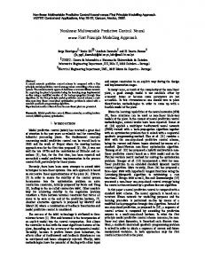
is divided into smaller sub-variation perturbation so that the PA solution can be applied to each one [27, 28]. It has been shown in several applications that a good trade-off between efficient computation and accurate optimization can be achieved [1, 14, 28]. In Chapter II, the detailed IPA-SQP algorithm, including a flow chart illustrates the main steps of the IPA-SQP algorithm [1] and the key equations involved, will be described. A PNE algorithm applicable to simultaneous control trajectory and parameter optimization has also been proposed by Ghaemi et al. [30] (see also Gao et al. [58] for an application to ship path following). In Chapter IV, the detailed derivation is introduced. This dissertation develops solutions within the IPA-SQP framework for AMPC and the PNE approach for minimum-time MPC problems. It also explores several important applications of the IPA-SQP algorithm. To provide a context for the dissertation work, in the following subsections, background and literature review are provided for AMPC, minimum-time MPC, shipboard power management controllers, and MPC for spacecraft relative motion maneuvers.
1.2.4
Adaptive Model Predictive Control
Compared to a substantial amount of research on conventional MPC, progress on adaptive MPC (AMPC) for systems with constraints has been limited. AMPC has been identified as a vital research direction by Morari [59]. There are several challenges in the development of rigorous approaches to AMPC and in associated computations. In particular, the ‘separation principle’ used for most certainty equivalence designs in indirect adaptive control may not hold in general class of nonlinear systems [60, 61]. In addition, the control law does not have a closed-form solution and has to be computed numerically in MPC. Furthermore, since the parameter identification is intertwined with the feedback loop, the closed9
loop performance of AMPC depends on both estimation and optimization, as well as their interactions. Finally, the predictive constraint enforcement based on an adaptive model requires special care. Early developments in AMPC have been in the area of the generalized predictive control (GPC) [62, 63, 64, 65], for which general state and output constraints have not been treated. More recent work on AMPC includes, for example, linear AMPC considered in [66], and AMPC using multiple linear models in [67, 68, 69, 70]. For nonlinear systems, the development of AMPC solutions has generally proceeded in two directions. Several of the approaches rely on the argument of parameter convergence to apply the ‘separation principle’. For example, [71] shows that under appropriate assumptions, there must exist a finite time period when the persistent excitation condition is satisfied (during which period the trajectories are assumed to be bounded) and, therefore, parameter convergence is achieved. In [66], additional constraints are included to ensure persistent excitation for online parameter identification. In [72], a different approach is taken to design an Input-to-State Stable (ISS) control Lyapunov function to provide robust stabilization for the closed-loop system without adaptation, and at the same time to ensure asymptotic stability with parameter adaptation for a class of unconstrained nonlinear systems. Another approach to integrating the adaptation into MPC is by ensuring sufficient ‘robustness’ while the estimation is still in progress. This is the approach taken, for instance, by [60, 73, 74, 75], where a set valued description of parameter uncertainty is adapted, and a robust min-max MPC is implemented for the identified parameter set. While this approach can deal with constraints, the underlying min-max feedback MPC problem can be computationally prohibitive to solve, especially in real-time. The approach pursued in this dissertation is motivated by the need to integrate optimization-based control solutions with online parameter identification algorithms for hybrid propulsion systems arising in aerospace, marine, and automotive domains.
10
These systems involve multiple heterogeneous power plant and load networks, have stringent safety and self sustainability requirements, and are expected to operate in wide range of conditions over their long life cycle. Moreover, they require fast sampling given their fast dynamics, yet they have limited on-board memory and computing power due to cost and space constraints. Consequently, efficient AMPC algorithms are necessary to handle real-time optimization, physical and operational constraints, and online identification and adaptation. An indirect AMPC algorithm based on the IPA-SQP framework is proposed in Chapter III aimed at developing efficient algorithms to integrate adaptation and optimization. Exploring the structure of the neighboring extremal solution, parameter updates are treated, together with updated initial conditions as the states are evolving, as perturbations in the MPC problem formulation. The IPA-SQP framework is used to derive an algorithm for a fast computation/update of the control sequence.
1.2.5
Minimum-time Model Predictive Control
Minimum-time optimal control problems have been well studied, see e.g., [31, 76, 77, 78, 79]. In simple cases, such as for a double integrator with control constraints, a feedback law can be computed explicitly. In more general cases, obtaining a closedform solution for a feedback law is a challenging task and a minimum-time open loop (feed-forward) trajectory is generated numerically by applying either direct methods (such as the direct shooting method, penalty function method, and SQP) or indirect methods (such as the multiple shooting method and collocation method), see e.g., [80, 81]. To provide robustness to unmeasured uncertainties and disturbances, openloop control can be augmented with a feedback stabilizer to the computed open-loop trajectory. References [82, 83] developed another approach to minimum-time control for linear systems in discrete-time based on set theoretic techniques. Applying MPC philosophy to minimum-time control involves recomputing the
11
open-loop state and control trajectory subject to pointwise-in-time state and control constraints, terminal state constraint, and the current state as the initial conditions. The computed control trajectory is applied open-loop till the next time instant when it is recomputed. As in traditional MPC, see [6], by recomputing the minimum-time control based on updated state information, robustness to unmeasured disturbances and uncertainties is improved. Many spacecraft and airplane control problems can be formulated as the minimumtime control problem. Some of them have been solved using MPC. For instance, the low thrust orbital maneuvering and for hypersonic vehicle guidance problems are solved in [84, 85]. The basic MPC strategy solves the minimum-time optimal control problem over a horizon and obtains the optimal control as a function of time as a vehicle progresses along its trajectory. The detailed procedure to formulate a problem for minimum-time MPC is provided in Chapter V. In these applications, minimumtime MPC has been used to improve robustness to unmeasured disturbances and uncertainties. For instance, the ability to perform Earth-to-Mars low thrust orbital transfers despite thrust errors and perturbation forces has been demonstrated in [84]. Additionally, the finite-time convergence of the minimum-time control is advantageous for applications that involve way-point following. In hypersonic vehicle applications, way points have to be reached in minimum time subject to exclusion zone and control input constraints (see [85]). The fact that the minimum-time feedback control possesses finite time stability and robustness properties is easily seen in continuous time. The cost-to-go function, V (x), under appropriate assumptions, satisfies the Bellman equation, V˙ (t) = −1, leading to finite-time convergence of V (x(t)) to 0 and x(t) to xT , where xT denotes the target state (e.g. a way point) for the minimum-time control [84]. If the perturbations do not destroy the property, V˙ (t) ≤ ε < 0, it is shown in [84] that finite-time convergence is maintained despite these perturbations. The minimum-time MPC
12
solutions represent an approximation to the minimum-time feedback control. To generate the minimum-time MPC law, however, a fast nonlinear optimizer is necessary in real-time implementation. In this dissertation, a methodology using the PNE approach for minimum-time MPC is developed.
1.2.6
Real-time Optimization for Shipboard Power Management
Shipboard integrated power systems (IPS) have been investigated as the key enabling technology in ship electrification for applications including warships and high value commercial ships [86, 87]. They provide electrical power for both the propulsion system and service loads, and rely on power management control (PMC) strategies to coordinate the power sources and loads for efficient and safe operation. The goals of PMC strategies are to achieve efficient and robust operation and to meet various dynamic requirements in diverse and sometimes adverse conditions. Moreover, effective PMC strategies are expected to provide improved fuel efficiency, enhanced response speed, and superior reliability in real-time [88]. To accomplish this, PMC must deal effectively with nonlinear system dynamics and stringent constraints to protect and operate the components involved. In addition, PMC must be flexible and easy to tune in order to manage trade-offs and re-balancing performance attributes. Several approaches have been proposed for shipboard PMC with IPS. An automatic rule-based expert system is proposed for the reconfiguration of shipboard IPS to enhance survivability of naval ships in [89]. In [90], an automated self-healing strategy is investigated by solving an optimization problem with constraints using a linear programming algorithm. In [91], a decentralized control approach using an intelligent multi-agent system for shipboard power systems is proposed. A number of research groups have developed shipboard PMC strategies using the real-time optimization framework. For example, a fast reconfiguration algorithm based on zone selection differential protection schemes is reported in [92]; however,
13
[92] provides no evidence that the algorithm can be implemented in real time. In other studies, real-time simulation results are reported. For instance, in [93], using the small population-based particle swarm optimization method, a fast intelligent reconfiguration algorithm is implemented on a real-time simulator. Reference [94] pursues a methodology that exploits time scale separation to achieve real-time optimization of a shipboard IPS. By solving a two-level simplified optimization problem, the realtime computational efficiency is achieved and validated on a real-time simulator. Most studies for PMC strategies in the optimization-based framework demonstrate the real-time feasibility using real-time simulations. To the author’s best knowledge, however, no study has demonstrated optimization-based PMC strategies with test results on a physical platform.
1.2.7
MPC for Spacecraft Relative Motion Maneuvers
Autonomous spacecraft relative motion maneuvers, including rendezvous and docking, are important and difficult parts of modern spacecraft missions.
Examples
of spacecraft relative motion maneuvering problems and solutions can be found in [95, 96, 97] and references therein. For instance, to recover a tumbling/out-of-control satellite that may exhibit complicated motion, a transport vehicle has to approach the International Space Station, and it has to avoid debris/obstacle appearing on the spacecraft path. The rendezvous and docking problems lead to control problems with pointwise-in-time and terminal constraints imposed on both state and control variables. For instance, the approaching spacecraft must maintain its position within a Line-of-Sight (LOS) cone from the docking port on the target platform [98, 99, 100, 101]. In addition, terminal translational velocity of the spacecraft must match the velocity of the docking port to ensure soft-docking [99, 102]. Collisions with debris/obstacle emerging on the spacecraft path must be avoided, and the spacecraft fuel consumption must be minimized
14
in addition to satisfying constraints during the maneuvers. Spacecraft rendezvous and docking problems have received significant attention in the literature, see [99, 101, 103, 104, 105, 106] and references therein. Various approaches have also been proposed for spacecraft rendezvous and docking based on variants of the MPC framework [107]. An MPC strategy with a variable horizon has been developed in [108]. In this strategy, auxiliary integer variables are introduced to represent the state of the mission at a given time (specifically whether a prescribed ‘box’ around the docking port is reached or yet to be reached) and the problem is treated as a mixed integer programming problem where the objective function is the weighted sum of fuel consumption and maneuver time. In [99], the strategy is extended to obtain failure-safe trajectories. In [109], a ‘rubber band’ MPC controller is proposed. In [110], the authors propose an application of MPC to spacecraft navigation in proximity of a space station. For guidance to the neighborhood of the space station, an unconstrained MPC is used while a constrained spacecraft attitude controller maintains the LOS between the space station and the spacecraft. The available spacecraft computing power is restricted in most spacecraft missions, including not only nanosats and cubesats but also high end spacecraft. Therefore, the MPC solutions to spacecraft relative motion control problems must have low computing effort in order to be feasible.
1.3
Contributions
This dissertation deals with methodologies for AMPC and minimum-time MPC that can be developed by exploiting the IPA-SQP and PNE approaches, and with specific applications that require real-time implementation of NMPC using the IPASQP approach. The contributions of this dissertation include both the development of methodological extensions to the IPA-SQP approach to AMPC and minimumtime MPC and the specific applications of MPC using IPA-SQP algorithm. The 15
contributions are summarized as follows: 1) As a methodological extension to the IPA-SQP framework, an indirect AMPC algorithm is developed to effectively integrate adaptation and constrained dynamic optimization. The AMPC algorithm based on IPA-SQP facilitates fast updates of the control sequence when model parameters change [111]. Thus IPA-SQP enables computationally efficient implementation of AMPC. 2) The conditions for the existence of a NE solution have been derived in the parametric optimal control problem to guarantee applicability of PNE in special cases. The obtained conditions provide insight into assumptions that are needed in future analysis of NE solution existence in more general situations. 3) A methodological extension to the PNE approach has been developed for minimumtime nonlinear MPC problems. To achieve this, the minimum-time MPC problem is transformed to make the PNE algorithm applicable. The existing results on PNE cannot be directly applied to the minimum-time MPC since the time horizon does not stay constant over time. A time scaling transformation, therefore, is employed to obtain a fixed end time problem, with the terminal time appearing as a multiplicative parameter in the dynamic equations of the continuous-time model. The model is then converted to discrete-time, and an optimization problem is obtained where both the control sequence and the time horizon, now appearing as a parameter, have to be optimized. A double integrator system is used to evaluate the effectiveness of the minimum-time MPC approach by means of PNE, and to demonstrate the improved robustness in closed-loop control with minimum-time MPC versus executing an open-loop trajectory. The simulation results on a nonlinear system corresponding to a hypersonic glider model show computational advantages of performing control updates using the PNE approach over an application of MATLAB fmincon
16
solver [112]. 4) A novel PMC for a shipboard power system that successfully uses the IPA-SQP approach for NMPC in real-time has been developed, analyzed, and tested on the simulation model, the Opal-RT real-time simulator, and the physical test bed [113]. An optimization-oriented model is derived for MPC design from the transient power management model (TPMM) [114], which is a low-order simulation model of the physical test bed of the shipboard power system. The performance of the IPA-SQP-based MPC controller is analyzed using the TPMM as the virtual test bed through both non-real-time and real-time simulations. The developed controller is implemented on the physical test bed to evaluate its performance in several proposed operational scenarios. This is the first reported result that demonstrates an optimization-based PMC strategy with test results on a physical shipboard platform. 5) Model predictive controllers have been developed and analyzed for spacecraft relative motion maneuvering [107, 115, 116, 117, 118]. A linear quadratic MPC (LQ MPC) coupled with dynamically reconfigurable linear constraints has been developed in this dissertation. This LQ MPC approach is feasible for implementation on-board of the spacecraft as it reduces to an online solution of QP for which effective numerical solvers exist. The LQ MPC, however, does not enable the direct handling of nonlinear constraints such as that on the 2-norm of thrust command relevant to single thruster spacecraft configurations. Hence IPA-SQP MPC approach developed in this dissertation is applied to solve the NMPC problem arising in spacecraft relative motion maneuvers. Simulation results on an example of spacecraft proximity maneuvering demonstrate that the nonlinearities in the problem, such as in the thrust constraints, can be handled effectively using the IPA-SQP algorithm. The results also show the poten-
17
tial for fuel efficiency improves with the IPA-SQP as compared to conventional thrust command saturation strategy augmented to the LQ MPC approach. The computation time with the IPA-SQP is reduced as compared to an application of MATLAB nonlinear programming solver fmincon. The LQ MPC has been applied to other examples, such as docking to a rotating platform and debris collision avoidance, and demonstrated through simulations its capability of efficient maneuvers. Most of the results outlined above have been documented and published or submitted in archived journals and/or referred conference proceedings [107, 111, 112, 113, 115, 116, 117, 118].
1.4
Dissertation Outline
The dissertation is organized as follows: In Chapter II, an overview of the IPA-SQP algorithm is provided. This chapter includes the detailed algorithm description and overview of key equations involved in the algorithm. Chapter III presents an AMPC algorithm that integrates a parameter estimation with the MPC based on the IPA-SQP approach. The AMPC algorithm is derived within the IPA-SQP framework to facilitate fast updates of the control sequence when model parameters change. The detailed algorithm derivation is provided, along with discussions on the performance and implementation. Chapter IV introduces the PNE framework and its derivation. It is shown that the NE solution satisfies the first-order optimality conditions for the auxiliary ‘linearized’ problem. The conditions on existence of an NE solution are derived for PNE in a special case. In Chapter V, a minimum-time MPC problem is considered. By employing a time
18
scaling transformation and cost regularization, it is shown that the problem becomes amenable to the application of the PNE approach. Simulation results for a double integrator system and for a hypersonic vehicle model are demonstrated. In Chapter VI, a PMC for a shipboard power system is developed. The shipboard power system and its control objectives are described, and the simulation model is introduced. Then, the MPC problem with constraints is formulated to design the PMC, considering various operational requirements and constraints. Simulation results with the TPMM on a real-time simulator are reported and analyzed. The experimental results on the physical test bed are presented and analyzed. Chapter VII presents predictive controllers based on LQ MPC and on IPA-SQP for spacecraft relative motion maneuvers. First, the LQ MPC and the IPA-SQP MPC are compared in a spacecraft proximity maneuvering example with nonlinear thrust constraints. It is shown that the IPA-SQP algorithm handles the nonlinear constraints directly while directionality-preserving scaling has to be applied to the output of the LQ MPC controller. Computation time and solution accuracy of the IPA-SQP MPC are compared with the results by fmincon function of MATLAB. The IPA-SQP algorithm has much lower computing time at the same level of accuracy versus fmincon. The results of LQ MPC on spacecraft applications such as rendezvous/docking and debris avoidance maneuvers are also reported. Chapter VIII provides conclusions and discusses future research plans.
19
CHAPTER II
IPA-SQP Algorithm
The IPA-SQP approach, developed for nonlinear MPC in [27, 28, 29], combines the solutions derived using perturbation analysis (PA) and sequential quadratic programming (SQP). This approach updates the solution to the optimization problem at time t by considering it as a perturbation to the solution at time (t − 1) using neighboring optimal control theory extended to discrete-time systems with constraints [31], and then corrects the results using one or more SQP updates. The merged PA and SQP updates exploit the sequential form of predictor and corrector steps, thereby yielding a fast solver for nonlinear MPC problems [14]. In this chapter, an overview of the IPA-SQP algorithm developed by Ghaemi et al. [14, 27, 28, 29, 30, 119] is provided for a self-contained presentation.
2.1
Perturbation Analysis Solution for Discrete-time Optimal Control Problem
The generic optimization problem associated with MPC is formulated over a receding horizon. Specifically, at a sampling instant t, we consider an optimal control
20
problem minimizing a general cost function with x ∈ Rn and u ∈ Rm ,
J(x(·), u(·)) = Φ(x(t + N )) +
t+N X−1
L(x(k), u(k)),
(2.1)
k=t
subject to x(k + 1) = f (x(k), u(k)), f : Rn+m 7→ Rn , x(t) = xt , xt ∈ Rn ,
(2.2)
C(x(k), u(k)) ≤ 0, C : R
n+m
l
7→ R , k = t, . . . , t + N − 1,
¯ C(x(k)) ≤ 0, C¯ : Rn 7→ Rp , k = t, . . . , t + N, where C and C¯ denote the mixed state-input constraints and pure state constraints, respectively, and xt is the state at the sampling instant t. We assume that the functions L, f, Φ, C, and C¯ are twice continuously differentiable with respect to their arguments. Let (x0 (·), u0 (·)) be the optimal solution of the optimization problem by (2.1) (2.2). The solution (x0 (·), u0 (·)) is referred to as the nominal solution in the context of the neighboring extremal (NE) analysis a The Hamiltonian function [120] is defined as H(k) =L(x(k), u(k)) + λT (k + 1)f (x(k), u(k)) (2.3) + µ (k)C (x(k), u(k)) + µ ¯ (k)C¯ a (x(k)), T
a
T
where λ(k) is the sequence of co-states associated with f (x(k), u(k)) (i.e., the dynamics of system), µ(k) and µ ¯(k) are the vectors of Lagrange multipliers, and C a (x(k), u(k)) and C¯ a (x(k)) denote vectors consisting of the active constraints. Before proceeding, we define compact notations for partial derivatives as follows: ∂ ∂ G(k), Gab (k) := Ga (k) := ∂a ∂b
21
�
� ∂ G(k) , ∂a
where the subscript letters a and b denote the variable with respect to which the partial derivative is taken, i.e., Hx and Hu denote the partial derivative of H with respect to x and u, respectively. Since the nominal solution (x0 (·), u0 (·)) is optimal, the following necessary optimality conditions are satisfied [42]: λ(k) = Hx (k), k = t, ..., t + N − 1, Hu (k) = 0, k = t, ..., t + N − 1, λ(t + N ) = Φx (x(t + N )),
(2.4)
µ(k) ≥ 0, k = t, ..., t + N − 1, µ ¯(k) ≥ 0, k = t, ..., t + N. The NE solution [31] approximates the optimal state and control sequences for the perturbed initial state so that the necessary conditions (2.4) for optimality are maintained to the first order. Consider the following optimization problem (see [1, 14, 28]):
¯ min δ 2 J, δx(·),δu(·)
where 1 δ J¯ = δxT (t + N ) 2 t+N −1 1 X δx(k) + 2 k=t δu(k) 2
� � � ∂ ¯ aT Φxx (t + N ) + C (t + N )¯ µ(t + N ) δx(t + N ) ∂x x T Hxx (k) Hxu (k) δx(k) , Hux (k) Huu (k) δu(k)
22
(2.5)
subject to
δx(k + 1) = fx (k)δx(k) + fu (k)δu(k),
(2.6)
δx(t) = δxt ,
(2.7)
Cxa (x(k), u(k))δx(k) + Cua (x(k), u(k))δu(k) = 0,
(2.8)
C¯xa (x(k))δx(k) = 0,
(2.9)
where δxt is defined as δxt := x(t) − x(t − 1). The solution to the problem (2.5) - (2.9) can be proceeded as follows: Before providing the NE solution, we introduce an approach because of the singularity problem when Cua (k) is not full rank at some time instant k (see [29]). To avoid the singularity issue, we propose the constraint back-propagation approach. When Cua (k) has dependent rows, it can be transformed through linear similarity transformation into the following form
˜a Cu (k) , 0
(2.10)
for some C˜ua (k) with independent rows. Hence, (2.8) can be decomposed into C˜xa (x(k), u(k))δx(k) + C˜ua (x(k), u(k))δu(k) = 0,
(2.11)
Cˆxa (x(k))δx(k) = 0,
(2.12)
for appropriately defined C˜xa (x(k), u(k)), C˜xu (x(k), u(k)), and Cˆxa (x(k)). Equation (2.12) can be expressed as
Cˆxa (x(k)) (fx (k − 1)δx(k − 1) + fu (k − 1)δu(k − 1)) = 0,
23
(2.13)
using (2.6). The constraint (2.13) is the results of back-propagating the constraint (2.9) to the sampling time (k − 1). We now define matrix sequences C˜u (·), C˜x (·), Cˆu (·), Cˆx (·), and S(·) using the following backward recursive equations. Define
Cˆxa (t + N ) := C¯xa (x(t + N )), S(t + N ) := Φxx (t + N ) +
(2.14)
� ∂ ¯ aT Cx (x(t + N ))¯ µ(t + N ) , ∂x
(2.15)
and at sampling instant k let Caug (k) :=
Cua (k) Cˆxa (k + 1)fu (k)
,
(2.16)
rk := rank(Caug (k)).
At each sampling instant k, there is a matrix P (k) that transforms matrix Caug (k) into the following form P (k)Caug (k) = P (k)
˜a Cu (k) , = a ˆ 0 Cx (k + 1)fu (k) Cua (k)
(2.17)
where the matrix C˜ua (k) ∈ Rrk ×m has independent rows. By defining
Cxa (k)
P (k) , a ˆ Γ(k) := C (k + 1)f (k) u x C¯xa (k)
(2.18)
and assuming that γk is the number of rows of matrix Γ(k), Γ(k) can be partitioned
24
a ˜ Cx (k) into a block matrix as Γ(k) = . We then obtain Cˆxa (k)
C˜xa (k)
� =
Cˆxa (k) =
�
Γ(k) ∈ Rrk ×m , � (γ −r )×m . I(γk −rk )×(γk −rk ) Γ(k) ∈ R k k
Irk ×rk 0rk ×(γk −rk ) � 0(γk −rk )×rk
By defining Z11 (k) := Hxx (k) + fxT (k)S(k + 1)fx (k), T Z21 (k) := Z12 (k) = Hux (k) + fuT (k)S(k + 1)fx (k),
(2.19)
Z22 (k) := Huu (k) + fuT (k)S(k + 1)fu (k), −1
˜ aT Z22 (k) Cu (k) K0 (k) := 0 C˜ua (k)
,
(2.20)
�
� S(k) := Z11 (k) −
Z12 (k) C˜xaT (k)
Z21 (k) K0 (k) , C˜xa (k)
(2.21)
T (t + N ) := 0, T (k) := fxT (k)T (k + 1)
� −
� Z12 (k) C˜xaT (k)
K0 (k)
fuT (k)T (k 0
(2.22)
+ 1) ,
where Z22 (k) > 0 for k ∈ [t, t + N ]. Hence, T (k) ≡ 0 for k ∈ [t, t + N ], but we keep T (·) in the equations to compare the form of the NE solution with that of the solution by the SQP approach in the next section. Using S(t + N ) and T (t + N ) as the terminal conditions for backward iteration, we calculate the matrix sequences described above. We then obtain the explicit relation between the state and input
25
variations of the perturbed solution as � δu(k) = −
� I 0
T Z21 (k)δx(k) + fu (k)T (k + 1) K0 (k) , a ˜ Cx (k)δx(k)
(2.23)
δx(k + 1) = fx (k)δx(k) + fu (k)δu(k), δx(t) = δxt .
When δxt is large and causes activity status changes in the constraints, δxt is divided into smaller segment and the NE solution is applied to each segment. Details in handling changes in the activity status of constraints are addressed in [14, 27, 28].
2.2
Sequential Quadratic Programming Based on Active Set Method
In this section, the SQP method is formulated for the problem (2.1) - (2.2) before introducing the IPA-SQP approach in the next section. The SQP method presented in this section extends a method in [121] to the cases with inequality constraints. We consider a feasible initial guess of the state x(·), control input u(·), sequence of co-states λ(·), and vectors of Lagrange multipliers µ(·) and µ ¯(·) associated with the inequality constraints in (2.2) and the necessary optimality conditions (2.4). Since the initial guess is not an optimal solution, the optimality condition,
Hu (k) = 0,
(2.24)
may not be satisfied. The inequality constraints at the sampling time k are treated as the equality constraints when they are active during the active set iteration. The corrections δx(k) and δu(k) are obtained as the solution of the following equality
26
constrained quadratic programming (QP) problem for the linearized system [14, 122]
min
t+N X−1
δx(·),δu(·)
HuT (k)δu(k) + δ 2 J¯
(2.25)
k=0
subject to δx(k+1) = fx (k)δx(k)+fu (k)δu(k), δx(t) = 0, (2.26) Cxa (x(k), u(k))δx(k)
+
Cua (x(k), u(k))δu(k)
= 0,
C¯xa (x(k))δx(k) = 0. The solution of the QP subject to the constraints in (2.26) is given by
� δu(k) = −
� I 0
fuT (k)T (k
+ 1) + Hu (k) Z21 (k)δx(k) + K0 (k) , C˜ a (k)δx(k)
(2.27)
x
δx(k + 1) = fx (k)δx(k) + fu (k)δu(k), δx(t) = 0,
where K0 (k), Z22 (k), Z21 (k), Z11 (k), and S(·) are defined in (2.19), (2.20), and (2.21). Moreover, the matrix T (·) is calculated using the following backward recursive equations T (t + N ) := 0, T (k) := fxT (k)T (k + 1) � −
� Z12 (k) C˜xaT (k)
(2.28)
T fu (k)T (k + 1) + Hu (k) K0 (k) . 0
Using the solution of QP in (2.27), the active set method is implemented to deal with constraints (see [42, 123] and reference therein). At a time instant k, we first find the
27
minimum value of α that satisfies C(x(k) + αδx(k), u(k) + αδu(k)) = 0, (2.29) ¯ or C(x(k) + αδx(k)) = 0, where 0 < α ≤ 1, and δx(k), δu(k) are calculated from (2.27). If there exists such α that satisfies (2.29), then the corresponding inactive inequality constraint is added to the set of active constraints (i.e., the working set). At the next iteration the problem (2.25) is solved with the initial solution x(k) + αδx(k) and u(k) + αδu(k). If α does not exist, the signs of Lagrange multipliers µ(k) and µ ¯(k) are examined. If all the Lagrange multipliers are nonnegative, it means the necessary optimality conditions are satisfied. If Z22 (k) > 0, then we have reached a local optimal solution. On the other hand, if there are negative Lagrange multipliers, one inequality constraint with a negative multiplier is deleted from the set of active constraints.
2.3
IPA-SQP Approach
In this section, we review how the perturbation analysis and SQP are unified to achieve fast convergence and to obtain an accurate optimal solution for the perturbed problem, given the nominal optimal solution. The IPA-SQP algorithm [14, 28] combines the computational advantages of the PA approach in predicting the solution and the ability of the SQP to further correct it. Comparing the two optimization problems (2.1) and (2.25), we note that the solution to the problem (2.25) is identical to that of (2.1) if we set Hu (k) = 0 and δx(t) = δxt in (2.27) and (2.28). Based on this observation, the following formulation,
28
which merges the two optimization steps into one, is proposed: � δu(k) = −
� I 0
T Z21 (k)δx(k) + fu (k)T (k + 1) + Hu (k) K0 (k) , a ˜ Cx (k)δx(k)
(2.30)
δx(k + 1) = fx (k)δx(k) + fu (k)δu(k), δx(t) = δxt .
The correction δu(·) calculated using (2.30) compensates for the initial state perturbation δxt , and it corrects the solution to enforce Hu (k) = 0 condition. Through this combination, a more computationally efficient algorithm is obtained as compared to SQP. The flow chart Figure 2.1 illustrates main steps of the IPA-SQP algorithm to obtain the NE solutions and to deal with changes in the activity status of constraints. It is shown in [28] that (2.30) yields local quadratic convergence rates similar to the conventional SQP. At the same time, due to integration of the NE-based prediction, the computing time and effort are typically similar to the NE algorithm. For instance, they tend to increase linearly rather than cubically in the horizon length, N . Examples considered in [28, 119] and references therein confirm that the method is computationally faster than the conventional SQP algorithm for discrete-time optimal control problems. In particular, a comprehensive computational benchmark analysis for a ship steering problem with a rather long prediction horizon (N = 140) was reported in [14], and substantial computation time reduction, without compromising performance, was demonstrated compared to SQP algorithm. Experimental results of IPA-SQP MPC were obtained at the sampling time of 100 µs for a full bridge DC/DC converter in [1].
29
Figure 2.1: Flowchart of the IPA-SQP algorithm [1].
30
CHAPTER III
Adaptive Model Predictive Control
In this chapter, an approach and a specific algorithm to integrate a parameter estimation with the receding horizon model predictive control are proposed. This adaptive MPC algorithm is developed based on the IPA-SQP framework. It is shown that an algorithm can be derived in the IPA-SQP framework to perform MPC updates when model parameters are changed. The detailed algorithm derivation is presented, along with discussions on the performance and implementation. An example based on the nonlinear dynamics of an inverted pendulum on a cart is included to demonstrate the effectiveness of the proposed algorithm.
3.1
Problem Formulation
Consider a typical adaptive control problem where the system state equations and constraints are described by
x(k + 1) = f (x(k), u(k), θ),
(3.1)
C(x(k), u(k), θ) ≤ 0,
(3.2)
and
31
with x ∈ Rn , u ∈ Rm , and θ ∈ Rp being the state, input, and parameter vectors, respectively. The functions f and C are assumed to be twice continuously differentiable with respect to all their arguments. Note that both system dynamics and constraints can depend on the plant parameter, θ, which captures changes and uncertainties in the physical system and in the constraints. If the parameter θ is known, a receding horizon optimization problem can be formulated to minimize a general cost function,
J(x(·), u(·), θ) = Φ(x(t + N )) +
t+N X−1
L(x(k), u(k), θ),
(3.3)
k=t
with respect to the control sequence u(·) over the prediction horizon [t, t+ N ], subject to the dynamic equation (3.1) and the mixed state and input constraints (3.2). When the plant parameters θ are unknown, they are assumed to be estimated with appropriately designed adaptation/online identification algorithms, leading to AMPC.
3.2
Indirect Adaptive MPC in IPA-SQP Framework
We seek to develop computationally fast AMPC algorithms that can effectively integrate adaptation and constrained dynamic optimization. Towards this end, we extend to the adaptive case the computational framework IPA-SQP developed for non-adaptive and nonlinear MPC. The IPA-SQP described in Chapter II provides a general framework for efficient computation of optimal solutions when some of the problem parameters, such as the initial condition, are changed. This problem formulation naturally applies to AMPC where the parameters are updated through an online identification mechanism. In this section, we develop the AMPC algorithm using the IPA-SQP framework, and explore the properties of the resulting AMPC scheme. We consider the indirect AMPC where the adaptive control scheme is designed using the certainty equivalence principle. Namely, the adaptation is performed by
32
combining a separate estimation algorithm that provides an estimate θˆt at time t for θ and then computing the MPC control action by minimizing the cost function
J(xt (·), ut (·), θˆt ) = Φ(xt (t + N )) +
t+N X−1
L(xt (k), ut (k), θˆt ),
(3.4)
k=t
subject to the dynamic equation for the estimated plant model
xt (k + 1) = f (xt (k), ut (k), θˆt ),
(3.5)
C(xt (k), ut (k), θˆt ) ≤ 0,
(3.6)
and estimated constraints
for k ∈ [t, t + N − 1] until the next time when the parameter θˆt and information on states are updated. In (3.4)-(3.6), xt (k) and ut (k) denote the prediction of x(k) and u(k), respectively, using information available at time t, and xt (t) = x(t). 3.2.1
Neighboring Extremal Solution for AMPC
Assume that the adaptive law for updating the parameter vector θˆt takes the form of θˆt = θˆt−1 + ht (x, u, θˆt−1 ),
(3.7)
δ θˆt := θˆt − θˆt−1 = ht (x, u, θˆt−1 ).
(3.8)
or
The AMPC algorithm is based on the following NE solution NE solution for AMPC: The control and state sequences ut (·) and xt (·) can be predicted as: ut (k) = ut−1 (k − 1) + δu(k), xt (k) = xt−1 (k − 1) + δx(k)
33
(3.9)
for k ∈ [t, t + N − 1], where
ut−1 = [ut−1 (t − 1), ut−1 (t) · · · , ut−1 (t + N − 2)], xt−1 = [xt−1 (t − 1), xt−1 (t) · · · , xt−1 (t + N − 2)]
are the control and state sequences resulting from the MPC optimization at the previous sampling time (t − 1). The correction terms δu(k) and δx(k) are calculated as: δu(k) = K1 (k)δx(k) + K2 (k)δ θˆt , δx(k + 1) = fx (k)δx(k) + fu (k)δu(k) + fθˆδ θˆt
(3.10)
where f(·) denotes the partial derivative of the function f with respect to the corresponding variable (·) along the solution xt−1 , ut−1 . The time-varying gains K1 (k) and K2 (k) are defined as:
Z21 (k) K0 (k) ∈ Rm×n , a Cx (k) � � Z23 (k) K2 (k) = − I 0 K0 (k) ∈ Rm×p , a Cθˆ (k) �
K1 (k) = −
�
I 0
where
(3.11)
(3.12)
−1
aT Z22 (k) Cu (k) K0 (k) = Cua (k) 0
,
(3.13)
a and C a denotes the vector of active constraints, and C(·) refers to partial derivative
of the active constraints with respect to the appropriate variable. Z2i , i = 1, 2, 3 are matrices calculated through a backward-in-time iterative procedure, as defined in the next subsection in the derivation of the algorithm. Remark 3.1. It should be noted that the assumptions of Z22 being positive definite and Cua being of full row rank are made for the AMPC algorithm. These assumptions 34
are typically satisfied if local optimum is achieved at the time instant (t − 1) and the constraints involve the control input u explicitly. For state-only constraints where Cua = 0, K0 in (3.11) and (3.12) will be singular and the algorithm cannot be applied directly. The constraint back propagation algorithms presented in [124] and Chapter II can be used to modify the AMPC algorithm and avoid singularity in (3.13), at the expense of additional computational complexity.
3.2.2
Derivation of NE Solution for AMPC
We now formally derive the AMPC algorithm and define the matrices used in (3.11)-(3.13). Consider the ‘certainty equivalence’ optimization problem defined by (3.4)-(3.6). The Hamiltonian for the optimization problem is defined as
H(k) =L(x(k), u(k), θˆt ) + λT (k + 1)f (x(k), u(k), θˆt ) + µT (k)C a (x(k), u(k), θˆt ),
(3.14)
with λ denoting the sequence of co-states and µ denoting the Lagrange multipliers. Let x∗ (·) = xt−1 (·), u∗ (·) = ut−1 (·), λ∗ (·) = λt−1 (·), µ∗ (·) = µt−1 (·) be the optimal solution obtained at (t − 1). Assuming that the Karush-Kuhn-Tucker (KKT) optimality conditions hold, it follows that
λ∗ (k) =
∂ H(x∗ (k), u∗ (k), λ∗ (k + 1), µ∗ (k), θˆt−1 ), ∂x
∂ H(x∗ (k), u∗ (k), λ∗ (k + 1), µ∗ (k), θˆt−1 ) = 0, ∂u
(3.15)
(3.16)
for all k ∈ [t, t + N − 1] and
λ(t + N ) =
∂ Φ(x∗ (t + N )). ∂x
35
(3.17)
Considering the change in the initial condition δxt and the parameter estimate δ θˆt as the perturbations in the optimization problem formulation, we can write (3.15)-(3.17) in the perturbation form:
δλ(k) =Hxx (k)δx(k) + Hxu (k)δu(k) + fxT (k)δλ(k + 1) + CxaT (k)δµ(k) + Hxθˆ(k)δ θˆt ,
(3.18)
Hux (k)δx(k) + Huu (k)δu(k) + fuT (k)δλ(k + 1) + CuaT (k)δµ(k) + Huθˆ(k)δ θˆt = 0, (3.19) for k ∈ [t, t + N − 1] and
δλ(t + N ) = Φxx (t + N )δx(t + N ).
(3.20)
Writing the model equations and constraints in the perturbation form, we have
δx(k + 1) = fx (k)δx(k) + fu (k)δu(k) + fθˆ(k)δ θˆt ,
(3.21)
Cxa (k)δx(k) + Cua (k)δu(k) + Cθˆat (k)δ θˆt = 0.
(3.22)
Assume that δλ(k + 1) takes the form of
δλ(k + 1) = S(k + 1)δx(k + 1) + T (k + 1)δ θˆt ,
(3.23)
we have, from δλ(t + N ) = Φxx (t + N )δx(t + N ), that
S(t + N ) = Φxx (t + N ),
T (t + N ) = 0.
Using (3.23) in (3.18), we have
δλ(k) = Z11 (k)δx + Z12 (k)δu(k) + Z13 (k)δ θˆt + CxaT (k)δµ(k),
36
(3.24)
where
Z11 (k) = Hxx (k) + fxT (k)S(k + 1)fx (k), Z12 (k) = Hxu (k) + fxT (k)S(k + 1)fu (k),
(3.25)
Z13 (k) = Hxθˆ(k) + fxT (k)S(k + 1)fθˆ(k) + fxT (k)T (k + 1), for all k ∈ [t, t + N − 1]. Similarly, we can express (3.19) as
Z21 (k)δx(k) + Z22 (k)δu(k) + Z23 (k)δ θˆt + CuaT (k)δµ(k) = 0,
(3.26)
where
T Z21 (k) = Z12 (k),
Z22 (k) = Huu (k) + fuT (k)S(k + 1)fu (k),
(3.27)
Z23 (k) = Huθˆ(k) + fuT (k)S(k + 1)fθˆ(k) + fuT (k)T (k + 1).
Note that from (3.26) and (3.22)
Z21 (k)δx(k) + Z22 (k)δu(k) + Z23 (k)δ θˆt + CuaT (k)δµ(k) = 0, Cxa (k)δx(k) + Cua (k)δu(k) + Cθˆa (k)δ θˆt = 0.
(3.28)
Assuming Z22 (k) > 0 and Cua (k) is of full row rank, and defining K0 (k) in (3.13), we have
δu(k) Z21 (k) Z23 (k) ˆ = −K0 (k) δx(k) + δ θt . δµ(k) Cxa (k) Cθˆa (k)
37
(3.29)
Using (3.29) in (3.24), we have
Z21 (k) K0 (k) δx(k) a Cx (k) � � Z23 (k) ˆ + Z13 (k) − Z12 (k) CxaT (k) K0 (k) δ θt . Cθˆa (k) �
�
δλ(k) = Z11 (k) −
Z12 (k) CxaT (k)
(3.30)
Therefore, by defining S(k) and T (k) as Z21 (k) K0 (k) Cxa (k) � � Z23 (k) T (k) = Z13 (k) − Z12 (k) CxaT (k) K0 (k) Cθˆa (k) S(k) = Z11 (k) −
�
�
Z12 (k) CxaT (k)
,
(3.31)
,
(3.32)
we can compute all the matrices defined earlier in (3.11)-(3.13) and formulate the gains in the predictor-corrector controller form specified in (3.11) and (3.12). This completes the derivation of the AMPC algorithm described in Section 3.2.1.
3.2.3
AMPC with IPA-SQP
Similar to the non-adaptive case, successive application of the NE solution requires the assumption that Hu = 0 at the previous time step, which cannot be guaranteed with the NE solution alone. The IPA-SQP algorithm thus incorporates additional iterations at each time step. After the first iteration at time t using the extended NE solution, since no new update of θˆt is expected before the next sampling time (t + 1), the same IPA-SQP updates as delineated in Chapter II and [28] can be applied. Remark 3.2. Note that the NE solution is derived under the assumption that active constraint set is not changed by the perturbations. If the perturbations of δxt and δθt are large enough to result in change of active constraint set, these cases can be 38
treated with the same extended algorithm as developed in [119].
3.2.4
Properties of AMPC
As with all other indirect adaptive schemes [125], the behavior and properties of the closed-loop adaptive control system depend on both the control and parameter adaptation algorithms. The certainty equivalence principle based design assumes the adaptation law δ θˆt is ‘well-behaved’ in the sense that the measured observation error is converging and the parameter error is reducing. Examples of such ‘well-behaved’ adaptive algorithms include gradient, projection, and least squares algorithms [126]. For general nonlinear AMPC problems with constraints, since closed-form solutions for the optimization are in general not attainable, closed-loop stability and performance analysis is difficult. This is also the case for the AMPC algorithm derived in Section 3.2. In a special case where the system is linear, the cost is quadratic, and constraints are not imposed, however, we can obtain the closed-loop stability for AMPC: Consider a linear system described by the transfer function
y = Gp (z)u
(3.33)
where Gp (z) =
bn−1 z n−1 + bn−2 z n−2 + · · · + b1 z + b0 z n + an−1 z n−1 + · · · + a1 z + a0
ai , bi , i = 0, · · · , n − 1 are unknown parameters to be estimated. Let Zp (z) = bn−1 z n−1 + bn−2 z n−2 + · · · + b1 z + b0 , (3.34) n
Rp (z) = z + an−1 z
n−1
+ · · · + a1 z + a0 .
39
Then (3.33) can be expressed as
[1 + θa∗ αn−1 (z)] y = θb∗T αn−1 (z)u,
(3.35)
�T � where αi (z) = z −1 , z −2 , . . . , z −(i−1) , z −i , and θa∗ = [an−1 , an−2 , . . . , a0 ]T , θb∗ = [bn−1 , bn−2 , . . . , b0 ]T
are the unknown parameter vectors. Putting (3.35) in the form:
y(t) = θp∗T φ(t),
(3.36)
� �T where θp∗ = θb∗T , θa∗T , and φ(t) = [u(t−1), u(t−2), . . . , u(t−n), −y(t−1), −y(t−2), . . . , −y(t−n)]T .
The adaptive laws for estimating on-line the vector θp∗ can be found. (See [125, 127].) Consider a gradient algorithm for the nth-order plant, we obtain the following adaptive law θˆp (t + 1) = θˆp (t) + Ψ�(t)φ(t), y(t) − θˆpT (t)φ(t) �(t) = , m2 (t)
(3.37)
where Ψ = ΨT > 0 is the adaptive gain matrix and m2 (t) = 1+φT (t)φ(t). In addition, the adaptive law that estimates θ∗ satisfies [125]: 1) θˆp (t) is bounded. 2) �(t), θˆp (t), (θˆp (t) − θˆp (t − 1)) ∈ L∞ . 3) �(t), (θˆp (t) − θˆp (t − 1)) ∈ L2 . 4) �(t) → 0 as t → ∞. 40
5) |θˆp (t) − θˆp (t − 1)| → 0 as t → ∞. Here L∞ norm is defined as ||x||∞ , sup |x(i)|, i≥0
where i ∈ Z+ and we say that x ∈ L∞ when ||x||∞ exists, and the Lp norm is defined as ||x||p ,
∞ X
!1/p |x(i)|p
, 1 ≤ p < ∞.
i=0
We also consider the exponentially weighted L2 norm defined as
||xt ||2β ,
t X
!1/2 β (t−i) xT (i)x(i)
,
i=0
where 0 < β < 1 is a constant. The detailed properties on the L2β norm can be found in [125]. Then we obtain the following result using the adaptive law (3.37) and its properties. For simplicity of the exposition, we consider the simple case of regulation. The results can be extended to the more general case of tracking by following the same procedure in [125] to augment the controller properly. Theorem 3.3. Consider the linear system (3.33). If the AMPC algorithm is used to minimize the quadratic cost function
J = xT (t + N )Sf x(t + N ) +
t+N X−1
� y 2 (k) + γu2 (k) ,
(3.38)
k=t
where Sf = Sf (t) satisfies the discrete-time algebraic Riccati equation for the estiˆt , C) with Q = C T C and R = γ, then, the closed-loop system is mated system (Aˆt , B stable while y(t) → 0 as t → ∞. Here the unknown parameters in the transfer function ˆt , C) is of the linear system (3.33) are estimated using the adaptive law (3.37). (Aˆt , B the observer canonical state-space realization of the transfer function with estimated
41
ˆt ) is assumed to be controllable. parameters at the time instant t and (Aˆt , B Proof Consider an infinite-horizon LQ problem minimizing a cost function
J1 =
∞ X
xˆT (k)Qˆ x(k) + uT (k)Ru(k),
(3.39)
k=t
where Q = C T C, R = γ, and the estimated system is ˆt u(k), xˆ(k + 1) = Aˆt xˆ(k) + B (3.40) yˆ(k) = C xˆ(k), k ∈ [t, ∞). For existence of the LQ solution, we assume that the system is stabilizable and (Aˆt , C) is observable where Q = C T C (see [128]). The discrete-time algebraic Riccati equation for the problem by (3.39)-(3.40) is
ˆ ˆT ˆ ˆ T ˆ −1 ˆ T ˆ Pt = AˆT t Pt At − (At Pt Bt )(R + Bt Pt Bt ) (Bt Pt At ) + Q,
(3.41)
and Pt is a unique positive definite matrix [128]. The optimal solution of the infinite-horizon LQ problem is
u1 (k) = Ft xˆ(k), k ∈ [t, ∞),
(3.42)
ˆtT Pt B ˆt )−1 B ˆtT Pt Aˆt . Ft = −(R + B
(3.43)
where
Let Sf = Pt , then the finite-horizon LQ problem, which minimizes
T
J2 = xˆ (t + N )Sf xˆ(t + N ) +
t+N X−1
� xˆT (k)Qˆ x(k) + uT (k)Ru(k) ,
k=t
42
(3.44)
has the optimal control
u2 (k) = Fˆ (k)ˆ x(k), k = t, . . . , t + N − 1,
(3.45)
where ˆ T P (k + 1)B ˆt )−1 B ˆ T P (k + 1)Aˆt , Fˆ (k) = −(R + B t t
(3.46)
ˆ ˆ ˆ ˆT P (k + 1) = AˆT t P (k)At + At P (k)Bt F (k) + Q, P (N ) = Sf . Since P (t + N ) = Sf = Pt , P (t + N − 1) = P (t + N − 2) = . . . = P (t) = Pt and the optimal solution is the same as that of the infinite-horizon LQ problem by (3.39)-(3.40). ˆt ) is controllable, (Aˆt , C) is observable, and Sf is It can be shown that, if (Aˆt , B ˆt Fˆ (t) is the solution of the discrete-time algebraic Riccati equation (3.41), then Aˆt + B ˆt Fˆ (t))ˆ asymptotically stable [129]. Hence, the closed-loop system xˆ(t+1) = (Aˆt +B x(t) of the finite-horizon LQ problem is asymptotically stable and yˆ(t) → 0 as t → ∞ for frozen parameters, i.e., stability of the estimated plant is guaranteed. We now show that the output y(t) → 0 as t → ∞. To do that, we follow 4 steps as in [125]. Step 1. Develop state error equations. Assume that the state space form (A, B, C) of the linear system at time instant t is x(t + 1) = Ax(t) + Bu(t), (3.47) y(t) = Cx(t). The state observer at time instant t is
ˆt u(t) − L ˆ t (C eˆ(t) − y(t)), eˆ(t + 1) = Aˆt eˆ(t) + B
(3.48)
ˆ t can be chosen so that Aˆt − L ˆ t C = Ao where Ao is a constant stable matrix. where L
43
ˆt , C) is the observer canonical form, this can be easily achieved [125]. Since (Aˆt , B Let eo , x − eˆ be the observation error, then ˆ t C)eo (t) + θ˜a y − θ˜b u(t), eo (t + 1) = (Aˆt − L
(3.49)
y(t) = Ceo (t) + C eˆ(t).
(3.50)
and
We consider the control input in (3.45)
u(t) = Fˆ (t)ˆ e(t).
(3.51)
Hence, the developed state error equations are as follows: ˆ t Ceo (t), eˆ(t + 1) = Ac (t)ˆ e(t) + L e0 (t + 1) = Ao eo (t) + θ˜a y(t) − θ˜b u(t), (3.52) y(t) = Ceo (t) + C eˆ(t), u(t) = Fˆ (t)ˆ e(t), ˆt Fˆ (t) is asymptotically stable at each time instant t, θ˜a , where Ac (t) = Aˆt + B h iT T ˜ ∗ ∗ ˆ ˆ ˜ ˜ ˜ θa − θa = [˜ an−1 , a ˜n−2 , . . . , a ˜0 ] , θb , θb − θb = bn−1 , bn−2 , . . . , b0 . Step 2. Establish exponential stability for the homogeneous part of (3.52). ˆt ) is controllable, we have Fˆ (t) ∈ L∞ since the From the assumption that (Aˆt , B solution of the discrete Riccati equation, Pt = PtT > 0, exists and Pt ∈ L∞ . Hence, � � � � ˆ ˆ ˆ ˆ Ac (t) ∈ L∞ . Using θa (t) − θa (t − 1) , θb (t) − θb (t − 1) ∈ L2 guaranteed by the properties of the adaptive law, we have (Fˆ (t) − Fˆ (t − 1)), (Ac (t) − Ac (t − 1)) ∈ L2 . Therefore, we have that Ac (t) is a uniformly asymptotically stable matrix. Since Ao is a constant stable matrix, the exponential stability of the homogeneous part of (3.52) follows. 44
Step 3. Use the properties of the L2β norm and the Bellman-Gronwall (B-G) Lemma (see [125]) to establish signal boundedness. For simplicity, we denote ||(·)t ||2β for some 0 < β < 1 with || · ||. Applying Lemma 3.3.2 and 3.3.3 in [125] to (3.52), we obtain ||ˆ x|| ≤ c||Ceo ||, ||y|| ≤ c||Ceo || + c||ˆ x|| + c,
(3.53)
||u|| ≤ c||ˆ x|| + c||y|| + c, where c ≥ 0 denotes any finite constant, then ||y|| ≤ c||Ceo || + c, (3.54) ||u|| ≤ c||Ceo || + c. We now relate the term Ceo with the estimation error � by using the equation in (3.52) to express as Ceo =C(zI − Ao )−1 (θ˜a y − θ˜b u) =
[z n−1 z n−2 · · · z 1] ˜ (θa y − θ˜b u). det(zI − Ao )
45
(3.55)
Here we take Ao such that det(zI − Ao ) = z n . Then Ceo =˜ a0 (t−1)y(t−1) − ˜b0 (t−1)u(t−1) +a ˜1 (t−2)y(t−2) − ˜b1 (t−2)u(t−2) +a ˜2 (t−3)y(t−3) − ˜b2 (t−3)u(t−3) .. . +a ˜n−1 (t−n)y(t−n) − ˜bn−1 (t−n)u(t−n) =a ˜0 (t)y(t−1) − ˜b0 (t)u(t−1) � � + (˜ a0 (t−1) − a ˜0 (t))y(t−1) − ˜b0 (t−1) − ˜b0 (t) u(t−1)
(3.56)
+a ˜1 (t)y(t−2) − ˜b1 (t)u(t−2) � � ˜ ˜ + (˜ a1 (t−2) − a ˜1 (t)) y(t−2) − b1 (t−2) − b1 (t) u(t−2) .. . +a ˜n−1 (t)y(t−n) − ˜bn−1 (t)u(t−n) � � + (˜ an−1 (t−n) − a ˜n−1 (t)) y(t−n) − ˜bn−1 (t−n) − ˜bn−1 (t) u(t−n) = − θ˜pT (t)φ(t) + r1 , where � � r1 = (˜ a0 (t − 1) − a ˜0 (t)) y(t − 1) − ˜b0 (t − 1) − ˜b0 (t) u(t − 1) � � ˜ ˜ + (˜ a1 (t − 2) − a ˜1 (t)) y(t − 2) − b1 (t − 2) − b1 (t) u(t − 2) .. . � � + (˜ an−1 (t − n) − a ˜n−1 (t)) y(t − n) − ˜bn−1 (t − n) − ˜bn−1 (t) u(t − n).
In the adaptive law in (3.37), the normalized estimation error satisfies the equation
�m2 = θ˜pT (t)φ(t),
46
that can be used in (3.56), Ceo = −�m2 + r1 ,
(3.57)
From the definition of m2f , 1 + ||u||2 + ||y||2 , we can show that mf is a normalizing signal in the sense that φ/mf , m/mf ∈ L∞ for some 0 < β < 1. From the expression of r1 , and the normalizing properties of mf , we obtain ||Ceo (t)|| ≤ c||�(t)m(t)mf (t)|| + c||(θˆp (t) − θˆp (t − 1))mf ||.
(3.58)
Using (3.54) and (3.58) and in the definition of mf , we have the following inequality, m2f (t) ≤ c||�(t)m(t)mf (t)|| + ||(θˆp (t) − θˆp (t − 1))mf || + c,
or m2f (t) ≤ c||g(t)mf (t)|| + c, where g 2 (t) , �2 (t)m2 (t) + |θˆp (t) − θˆp (t − 1)|2 and g ∈ L2 . We can show mf ∈ L∞ using B-G Lemma. We can also establish boundedness for the rest of the signals using the properties of the L2β norm. Step 4. Convergence of the tracking error to zero. Since all signals are bounded as shown in Step 3, we can establish that |Ceo (t)| ∈ L2 and |Ceo (t)| → 0 as t → ∞ using the same procedure in page 523 of [125]. In (3.52), we also have ˆ t Ceo (t). eˆ(t + 1) = Ac (t)ˆ e(t) + L Then, eˆ(t) → 0 as t → ∞ since Ac (t) is uniformly asymptotically stable and |Ceo (t)| → 0 as t → ∞. Finally, from y(t) = Ceo (t) + C eˆ(t), we conclude that y(t) → 0 as t → ∞. Remark 3.4. In general cases that the reference signal is yr whose internal model
47
Qr (z), i.e., Qr (z)yr = 0, we consider the tracking error e1 (t) = y(t) − yr at time instant t. Using
e1 =
Zp (z) Zp (z)Q1 (z) u − yr = u¯, Rp (z) Rp (z)Qr (z)
where Q1 (z) is an arbitrary monic Hurwitz polynomial of degree q and u =
Q1 (z) u¯, Qr (z)
we can also show the closed-loop stability. (See [125] for the detailed proof.) Note that Theorem 3.3 implies that Sf is time-varying and needs to be recomputed online from the discrete Riccati equation for the estimated system to preserve stability. We also note that the preceding stability result does not require parameter convergence. On the other hand, it does not address constraints. In fact, the algorithm proposed in Section 3.2.1 enforces constraints in the certainty equivalence sense, and the effects of uncertainties and parameter errors on the constraints, namely, the possibility of loss of feasibility during adaptation, are not considered. Such extensions will be pursued in future work.
3.3
AMPC for an Inverted Pendulum on a Cart
An example, based on the nonlinear dynamic model of the inverted pendulum on the cart in Figure 3.1, is now considered. The state of the dynamic model is x = [x1 , x2 , x3 , x4 ]T , where x1 and x2 are the position and velocity of the cart, and x3 and x4 are the angle and angular velocity of the pendulum, respectively, with
48
Figure 3.1: An inverted pendulum on a cart. respect to the vertical direction. Based on the model given in [130], we have:
x˙ 1 = x2 , x˙ 2 =
gθ sin x3 cos x3 − lθx24 sin x3 + u , (M + θ) − θ cos2 x3
x˙ 3 = x4 , x˙ 4 =
(3.59) lθx24
g(M + θ) sin x3 − sin x3 cos x3 + u cos x3 , l(M + θ) − lθ cos2 x3
where u denotes the control force produced by an actuator in the horizontal direction. θ represents the mass of the pendulum ball, l is the length of the massless rod, and M is the mass of the cart. The discrete-time model of the system is obtained by sampling (3.59) at 10 Hz with T = 0.1 sec. We consider a stabilization problem where the objective is to control the angle and angular velocity of the pendulum with the unknown mass θ to zero subject to control constraints on the actuator. In the simulations, the values of θ = 0.05 kg (unknown to the controller), M = 2 kg, and l = 0.5 m are used. The control force is constrained so that −1.2 ≤ u(t) ≤ 1.2.
49
(3.60)
0.03
0.2
angular vel. (rad/s)
0.02
angle (rad)
0.01 0 −0.01 −0.02 −0.03
0.15
0.1
0.05
0
−0.04 −0.05 0
5
10
−0.05 0
15
5
time (sec) 1.5
15
0.355
0.35
1
0.345
0.5
θˆ
force (N)
10
time (sec)
0.34
0 0.335
−0.5
−1 0
0.33
5
10
0.325
15
time (sec)
0
5
10
15
time (sec)
Figure 3.2: Simulation result of the AMPC applied to the inverted pendulum dynamics. The incremental and terminal cost functions are defined as
L = xT Qx + uT Ru,
Φ = xT Sf x,
where we choose Q = diag(1, 1, 1, 1), R = 10, and Sf = 500 × Q. The prediction horizon is chosen as 10 steps in this example. ˆ = 0.35. As these plots The closed-loop response is shown in Figure 3.2 with θ(0) demonstrate, AMPC is able to drive the angle and angular velocity of the inverted pendulum to the desired equilibrium, while the parameter estimate θˆ converges. The control constraints are satisfied. Figure 3.3 compares the responses of three closedloop systems: (i) MPC applied to the plant model with θ = 0.05 when the parameter estimate θˆ = θ = 0.05 is accurate (Case A); (ii) MPC applied to the plant model with θ = 0.05 when the parameter estimate θˆ = 0.35 is inaccurate (Case B); and
50
1.5
0.04 Case A Case B Case C
u (N)
0.5 0 −0.5
0
−0.02
−0.04
−1 −1.5 0
Case A Case B Case C
0.02
angle (rad)
1
5
10
−0.06 0
15
5
time (sec)
15
0.5 Case A Case B Case C
0.2
Case A Case B Case C
0.4
velocity (m/s)
angular velocity (rad/sec)
0.25
0.15 0.1 0.05 0 −0.05 −0.1 0
10
time (sec)
0.3 0.2 0.1 0 −0.1
5
10
−0.2 0
15
time (sec)
5
10
15
time (sec)
Figure 3.3: Simulations compare three different responses: Case A: with perfect information of θ, Case B: with wrong initial estimate and without adaptation of θ, Case C: with wrong initial estimate and with adaptation of θ. ˆ = 0.35 (Case C). The (iii) AMPC applied with the initial parameter estimate of θ(0) weight matrices and other parameters are the same between these three controllers. In all three cases, the control constraints are satisfied. The response is improved with AMPC and it approaches to that of the MPC with known θ even though the parameter is not converging due to the lack of persistent excitation.
51
CHAPTER IV
Parametric Neighboring Extremal Algorithm
In this chapter, an overview of the PNE algorithm developed by Ghaemi et al. [30] for the MPC problem with adjustable parameters is provided. In addition, new theoretical aspects of the PNE are explored on the NE solution of the MPC problem with parameters (Theorem 4.1) and conditions for existence of the NE solution (Theorem 4.4).
4.1
Overview of the Parametric Neighboring Extremal Algorithm
4.1.1
Problem Formulation
The receding horizon optimization problem with adjustable parameters, at a sampling instant t, minimizes a general cost function,
J(x(·), u(·), p) = Φ(x(t + N ), p) +
t+N X−1 k=t
52
L((x(k), u(k), p),
(4.1)
subject to x(k + 1) = f (x(k), u(k), p), f : Rn+m+r 7→ Rn , x(t) = xt , xt ∈ Rn ,
(4.2)
C(x(k), u(k), p) ≤ 0, C : R
n+m+r
l
7→ R , k = t, . . . , t + N − 1,
¯ C(x(k), p) ≤ 0, C¯ : Rn+r 7→ Rq , k = t, . . . , t + N, where x(·), u(·), and p are state sequence, control sequence, and an adjustable parameter vector, respectively. The parameter vector, p, are included as optimization variables, which differentiates this problem from the one treated in the previous chapter where parameters where not adjustable. Let x0 (·), u0 (·), and p0 be the nominal optimal solution of the problem by (4.1)(4.2). To simple expositions, let ¯ ¯ C(k) := C(x(k), u(k), p), C(k) = C(x(k), p), Φ(t + N ) := Φ(x(t + N ), p), L(k) := L(x(k), u(k), p), f (k) := f (x(k), u(k), p). The Lagrangian function is defined as L(x(·), u(·), p, λ(·), µ(·), µ ¯(·)) = Φ(t + N ) +
t+N X−1
L(k)
k=t T
+ λ(t) (xt − x(t)) + +
t+N X−1 k=t
t+N X−1
µ(k)T C a (k) +
k=t t+N X k=t
53
λ(k + 1)T (f (k) − x(k + 1))
µ ¯(k)T C¯ a (k).
We also define the Hamiltonian function as follows: H(x(k), u(k), p, λ(k + 1), µ(k), µ ¯(k)) = L(k) + λ(k + 1)T f (k) + µT (k)C a (k) + µ ¯T (k)C¯ a (k). Then, using the Hamiltonian function H(x(k), u(k), p, λ(k + 1), µ(k), µ ¯(k)) the Lagrangian function is expressed as
L(x(·), u(·), p, λ(·), µ(·), µ ¯(·)) = Φ(t + N ) + λ(t)T xt − λ(t + N )T x(t + N ) + µ ¯(t + N )T C¯ a (t + N ) +
t+N X−1
� H(k) − λ(k)T x(k) .
(4.3)
k=t
The nominal solution (xo (·), uo (·), po ) is optimal and is assumed to satisfy the following first order necessary optimality conditions implied by the KKT theorem [42],
Lx(k) (x(·), p, λ(·)) = 0, k = t, . . . , t + N,
(4.4)
Lu(k) (x(·), p, λ(·)) = 0, k = t, . . . , t + N − 1,
(4.5)
Lp (x(·), p, λ(·)) = 0.
(4.6)
Then the following equations are derived
λ(k) = Hx (k), k = t, · · · , t + N − 1,
(4.7)
λ(t + N ) = Φx (t + N ) + µ ¯(t + N )T C¯xa (t + N ),
(4.8)
Hu (k) = 0, k = t, · · · , t + N − 1,
(4.9)
Φp (t + N ) + µ ¯(t + N ) C¯pa (t + N ) + T
t+N X−1 k=t
54
Hp (k) = 0,
(4.10)
where (4.7) and (4.8) are derived from (4.4), (4.9) is derived from (4.5), and (4.10) is derived from (4.6). The NE solution [31] is the first-order correction that approximates the optimal state and control sequences for the perturbed initial state, that is it maintains necessary conditions satisfied up to the first-order terms. We now demonstrate that the NE solution can be computed from necessary conditions for a ‘linearized’ problem, where the second-order variation of the Hamiltonian function of (4.1) is minimized subject to the linearized dynamic equations and constraints:
min
¯ δ 2 J,
(4.11)
δx(·), δu(·), δp
where,
T
1 δx(t + N ) Φ11 (t + N ) Φ12 (t + N ) δx(t + N ) 2 δp Φ21 (t + N ) Φ22 (t + N ) δp T δx(k) Hxx (k) Hxu (k) Hxp (k) δx(k) t+N −1 1 X δu(k) H (k) H (k) H (k) δu(k) , (4.12) + ux uu up 2 k=t δp Hpx (k) Hpu (k) Hpp (k) δp
δ 2 J¯ =
subject to
δx(k + 1) = fx (k)δx(k) + fu (k)δu(k) + fp (k)δp,
(4.13)
δx(t) = δxt ,
(4.14)
Cxa (k)δx(k) + Cua (k)δu(k) + Cpa (k)δp = 0,
(4.15)
C¯xa (k)δx(k) + C¯pa (k)δp = 0,
(4.16)
55
where ∂ ∂x ∂ Φ12 (t + N ) = Φxp (t + N ) + ∂p ∂ Φ21 (t + N ) = Φpx (t + N ) + ∂x ∂ Φ22 (t + N ) = Φpp (t + N ) + ∂p Φ11 (t + N ) = Φxx (t + N ) +
� µ ¯(t + N )T C¯x (t + N ) ,
(4.17)
� µ ¯(t + N )T C¯x (t + N ) ,
(4.18)
� µ ¯(t + N )T C¯p (t + N ) ,
(4.19)
� µ ¯(t + N )T C¯p (t + N ) ,
(4.20)
and all the partial derivatives are computed at the nominal solution. Theorem 4.1. The NE solution of Problem (4.1) satisfies the first-order optimality conditions in the problem of minimizing the second-order variation (4.11) subject to linearized constraints (4.13)-(4.16). Proof : We assume that the point (x(·), u(·), p, λ(·), µ(·), µ ¯(·)) is a regular KKT point of Problem (4.1) which satisfies the linear independence constraint qualification (LICQ) condition [42]. Consider perturbations:
x(·) + δx(·), u(·) + δu(·), p + δp, λ(·) + δλ(·), µ(·) + δµ(·), µ ¯(·) + δ µ ¯(·). Assume that t = 0 to simplify the presentation without loss of generality. By using
56
the first order approximation, (4.7)-(4.10) are expressed as
λ(k)+δλ(k) = Hx (k) + Hxx (k)δx(k) + Hxu (k)δu(k) + Hxp (k)δp + Hxλ δλ(k + 1) + Hxµ δµ(k) + Hx¯µ δ µ ¯(k), k = 0, . . . , N −1,
(4.21)
λ(N )+δλ(N ) = Φx (N )+Φxx (N )δx(N )+Φxp (N )δp+Φxλ (N )δλ(N )+Φx¯µ δ µ ¯(N ) � ∂ +µ ¯(N )T C¯xa (N ) + µ ¯(N )T C¯xa (N ) δx(N ) ∂x � � ∂ ∂ ¯(N ), (4.22) + µ ¯(N )T C¯xa (N ) δp + µ ¯(N )T C¯xa (N ) δ µ ∂p ∂µ ¯ Hu (k) + Hux (k)δx(k) + Huu (k)δu(k) + Hup (k)δp + Huλ δλ(k + 1) + Huµ δµ(k) + Hu¯µ δ µ ¯(k) = 0, k = 0, . . . , N −1,
(4.23)
Φp (N ) + Φpx (N )δx(N ) + Φpp (N )δp + Φpλ (N )δλ(N ) � ∂ µ ¯(N )T C¯pa (N ) δx(N ) +µ ¯(N )T C¯pa (N ) + ∂x � � ∂ ∂ + µ ¯(N )T C¯pa (N ) δp + µ ¯(N )T C¯pa (N ) δ µ ¯(N ) ∂p ∂µ ¯ N −1 X + [Hp (k) + Hpx (k)δx(k) + Hpu (k)δu(k) + Hpp (k)δp k=0
+ Hpλ δλ(k + 1) + Hpµ δµ(k) + Hp¯µ δ µ ¯(k)] = 0,
(4.24)
x(k + 1) + δx(k + 1) = f (k) + fx (k)δx(k) + fu (k)δu(k) + fp (k)δp, k = 0, ..., N − 1, x(0) + δx(0) = x0 + δx0 .
(4.25) (4.26)
57
Hence, the NE solution satisfies the following equations:
δλ(k) = Hxx (k)δx(k) + Hxu (k)δu(k) + Hxp (k)δp + fxT (k)δλ(k + 1) + Cxa (k)T δµ(k) + C¯xa (k)T δ µ ¯(k), k = 0, . . . , N −1, � � � ∂ T ¯a δλ(N ) = Φxx (N ) + µ ¯(N ) Cx (N ) δx(k) ∂x � � � ∂ T ¯a ¯(N ), µ ¯(N ) Cx (N ) δp + C¯xa (N )T δ µ + Φxp (N ) + ∂p
(4.27)
(4.28)
Hux (k)δx(k) + Huu (k)δu(k) + Hup (k)δp + fuT (k)δλ(k + 1) + Cua (k)δµ(k) = 0, k = 0, . . . , N −1, � � � ∂ T ¯a Φpx (N ) + µ ¯(N ) Cp (N ) δx(N ) ∂x � � � ∂ T ¯a + Φpp (N ) + µ ¯(N ) Cp (N ) δp ∂p N −1 X [Hpx (k)δx(k) + Hpu (k)δu(k) + Hpp (k)δp + fuT (k)δλ(k + 1) +
(4.29)
k=0
+ Cpa (k)T δµ(k) + C¯pa (k)T δ µ ¯(k)] = 0,
(4.30)
δx(k + 1) = fx (k)δx(k) + fu (k)δu(k) + fp (k)δp, k = 0, . . . , N − 1,
(4.31)
δx(0) = δx0 .
(4.32)
We now consider the minimization problem (4.12) subject to linearized constraints (4.13)-(4.16) where t = 0. The Lagrangian function of (4.12) is defined as
¯ L(δx(·), δu(·), δp, δλ(·), δµ(·), δ µ ¯(·)) = δ 2 J¯ + δλ(0)T (δx0 − δx(0)) +
+
N −1 X k=0 N −1 X k=0
δλ(k + 1)T (fx (k)δx + fu (k)δu(k) + fp (k)δp − δx(k + 1)) T
a
δµ(k) C (k) +
N X
δµ ¯(k)T C¯ a (k).
k=0
58
(4.33)
The Hamiltonian function is
¯ H(δx(k), δu(k), δp, δλ(k + 1), δµ(k), δ µ ¯(k)) T δx(k) Hxx (k) Hxu (k) Hxp (k) N−1 1 X δu(k) H (k) H (k) H (k) = uu up ux 2 k=0 δp Hpx (k) Hpu (k) Hpp (k)
δx(k) δu(k) δp
+ δλ(k + 1)T (fx (k)δx(k) + fu (k)δu(k) + fp (k)δp) + δµ(k)T C a (k) + δ µ ¯(k)T C¯ a (k).
(4.34)
Then, the Lagrangian function (4.33) is expressed using the Hamiltonian function (4.34),
¯ L(δx(·), δu(·), δp, δλ(·), δµ(·), δ µ ¯(·)) T 1 δx(N ) Φ11 (N ) Φ12 (N ) δx(N ) = 2 δp Φ21 (N ) Φ22 (N ) δp + δλ(0) δx0 − δλ(N ) δx(N ) + δ µ ¯(N ) C¯ a (N ) + T
T
T
N −1 X
¯ (H(k) − δλ(k)T δx(k)).
k=0
(4.35) The first order necessary optimality conditions from KKT conditions are, ∂ ¯ L(δx(·), δu(·), δp, δλ(·), δµ(·), δ µ ¯(·)) = 0, ∂(δx) ∂ ¯ L(δx(·), δu(·), δp, δλ(·), δµ(·), δ µ ¯(·)) = 0, ∂(δu) ∂ ¯ L(δx(·), δu(·), δp, δλ(·), δµ(·), δ µ ¯(·)) = 0, ∂(δp)
(4.36) (4.37) (4.38)
δx(k + 1) = fx (k)δx(k) + fu (k)δu(k) + fp (k)δp, k = 0, ..., N − 1,
(4.39)
δx(0) = δx0 .
(4.40)
59
Then, the following equations are obtained
δλ(k) = Hxx (k)δx(k) + Hxu (k)δu(k) + Hxp (k)δp + fxT (k)δλ(k + 1) + Cxa (k)T δµ(k) + C¯xa (k)T δ µ ¯(k), k = 0, . . . , N −1, � � � ∂ T ¯a δλ(N ) = Φxx (N ) + µ ¯(N ) Cx (N ) δx(k) ∂x � � � ∂ T ¯a ¯(N ), µ ¯(N ) Cx (N ) δp + C¯xa (N )T δ µ + Φxp (N ) + ∂p
(4.41)
(4.42)
Hux (k)δx(k) + Huu (k)δu(k) + Hup (k)δp + fuT (k)δλ(k + 1) + Cua (k)δµ(k) = 0, k = 0, . . . , N −1, � � � ∂ T ¯a Φpx (N ) + µ ¯(N ) Cp (N ) δx(N ) ∂x � � � ∂ T ¯a + Φpp (N ) + µ ¯(N ) Cp (N ) δp ∂p N −1 X [Hpx (k)δx(k) + Hpu (k)δu(k) + Hpp (k)δp + fuT (k)δλ(k + 1) +
(4.43)
k=0
+ Cpa (k)T δµ(k) + C¯pa (k)T δ µ ¯(k)] = 0,
(4.44)
δx(k + 1) = fx (k)δx(k) + fu (k)δu(k) + fp (k)δp, k = 0, . . . , N − 1,
(4.45)
δx(0) = δx0 .
(4.46)
Equations (4.27)−(4.32) and (4.41)−(4.46) are the same.
4.1.2
Computation of the NE Solution
As we decomposed the linearized constraints in Chapter II (see (2.11)-(2.13)), the constraints (4.15) and (4.16) can be expressed
C˜xa (k)δx(k) + C˜ua (k)δu(k) + C˜up (k)δp = 0,
(4.47)
Cˆxa (k)δx(k) + Cˆpa (k)δp = 0,
(4.48)
where C˜ua (k) is of full row rank. 60
Assume t = 0 and let δ µ ˆ(N ) := δ µ ¯(N ) and Cˆxa (N ) := C¯xa (N ). Define � ∂ µ ¯(N )T C¯xa (N ) , ∂x � ∂ T12 (N ) := Φxp (N ) + µ ¯(N )T C¯xa (N ) . ∂p
S11 (N ) := Φxx (N ) +
Note that the NE solution satisfies (4.41)−(4.46). Equation (4.42) can be written as
δλ(N ) = S11 (N )δx(N ) + T12 (N )δp + Cˆxa (N )T δ µ ˆ(N ).
(4.49)
Assume that δλ(k + 1) at the sampling time (k + 1) is represented as
δλ(k + 1) = S11 (k + 1)δx(k + 1) + T12 (k + 1)δp + Cˆxa (k + 1)T δ µ ˆ(k + 1).
(4.50)
Equation (4.41) can be written as
δλ(k) =Hxx (k)δx(k) + Hxu (k)δu(k) + Hxp (k)δp + fxT (k)λ(k + 1) + Cxa (k)T δµ(k) + C¯xa (k)T δ µ ¯(k) =Hxx (k)δx(k) + Hxu (k)δu(k) + Hxp (k)δp + Cxa (k)T δµ(k) + C¯xa (k)T δ µ ¯(k) + fxT (k)[S11 (k + 1)(fx (k)δx(k) + fu (k)δu(k) + fp (k)δp) + T12 (k + 1)δp + Cˆxa (k + 1)T δ µ ˆ(k + 1)].
(4.51)
Define
Z11 (k) := Hxx (k) + fxT (k)Z11 (k + 1)fx (k), Z12 (k) := Hxp (k) + fxT (k)Z11 (k + 1)fp (k), Z13 (k) := Hxu (k) + fxT (k)Z11 (k + 1)fu (k), (4.52)
61
and
Cxa (k)
P (k) a ˜ Cx (k) = a ˆ Γ(k) := , (k + 1)f (k) C u x Cˆxa (k) C¯xa (k) Cpa (k) P (k) = Λ(k) := Cˆxa (k + 1)fp (k) + Cˆpa (k + 1) a ¯ Cp (k)
(4.53)
C˜pa (k) . a ˆ Cp (k)
(4.54)
Then, we obtain
δλ(k) =Z11 (k)δx(k) + Z13 (k)δu(k) + [Z12 (k) + fxT (k)T12 (k + 1)]δp + C˜xa (k)T δ µ ˜(k) + Cˆxa (k)δ µ ˆ(k).
(4.55)
Equation (4.43) is expressed
[Hux (k) + fu (k)T S11 (k + 1)fx (k)]δx(k) + [Huu (k) + fu (k)T S11 (k + 1)fu (k)]δu(k) + [Hup (k) + fu (k)T S11 (k + 1)fp (k) + fu (k)T T12 (k + 1)]δp + fu (k)T Cˆxa (k + 1)δ µ ˆ(k + 1) + Cua (k)δµ(k) = 0.
Define
Z31 (k) := Z13 (k)T , Z33 (k) := Huu (k) + fuT (k)S11 (k + 1)fu (k), Z32 (k) := Hup (k) + fuT (k)S11 (k + 1)fp (k).
62
(4.56)
Then, we obtain
˜(k) = −Z31 (k)δx(k) − [Z32 (k) + fu (k)T T12 (k + 1)]δp. Z33 (k)δu(k) + C˜xa (k)T δ µ (4.57) From the constraint (4.47)
C˜ua (k)δu(k) = −C˜xa (k)δx(k) − C˜up (k)δp.
(4.58)
Using (4.57) and (4.58), T a ˜ Z33 (k) Cu (k) δu(k) 0 δµ ˜(k) C˜ua (k) T Z32 (k) + fu (k) T12 (k + 1) Z31 (k) = − δp. δx(k) − C˜pa (k) C˜xa (k)
Let
(4.59)
−1 a T ˜ Z33 (k) Cu (k) K0 (k) := . C˜ua (k) 0
(4.60)
δu(k) = K1 (k)δx(k) + K2 (k)δp,
(4.61)
Hence
where
Z31 (k) K0 (k) , a ˜ Cx (k) � � T Z32 (k) + fu (k)T12 (k + 1) K2 (k) = − I 0 K0 (k) . C˜pa (k) �
K1 (k) = −
�
I 0
63
We now simplify (4.44). Let
� S12 (k) := Z12 −
Z31 (k) K0 (k) C˜xa (k) � Z32 (k) C˜xa (k)T K0 (k) C˜pa (k)
Z13 C˜xa (k)T
S11 (k) := Z11 −
�
�
Z13
, ,
S21 (N ) := T12 (N )T , S21 (k) := S12 (k)T , � � T fu (k) T12 (k) := fx (k)T − Z13 C˜xa (k)T K0 (k) T12 (k + 1) + S12 (k), 0 T22 (N ) := Φpp (N ) +
� ∂ µ ¯(N )T C¯pa (N ) , ∂p
W22 (N ) := T22 (N ), Cˆp (N ) := C¯p (N ), µ ˆ(N ) := µ ¯(N ), Z21 (k) := Hpx (k) + fpT (k)S11 (k + 1)fx (k), Z22 (k) := Hpp (k) + fpT (k)S11 (k + 1)fp (k), Z23 (k) := Hpu (k) + fpT (k)S11 (k + 1)fu (k).
Then, (4.44) is expressed as
S21 (N )δx(N ) + W22 (N )δp + Cˆp (N )T µ ˆ(N ) +
N −1 X
[Z21 (k)δx(k) + Z23 (k)δu(k) + Z22 (k)δp + fpT (k)δλ(k + 1)
k=0
+ Cp (k)T δµ(k) + C¯p (k)T δ µ ¯(k)] = 0.
64
(4.62)
Using (4.54) and (4.59), (4.62) can be written as
S21 (N )δx(N ) + W22 (N )δp +
N −1 X
[Z21 (k)δx(k) + Z23 (k)δu(k) + Z22 (k)δp + fpT (k)δλ(k + 1) + C˜p (k)T δ µ ˜(k)]
k=0
= S21 (N )δx(N ) + W22 (N )δp +
N −1 X
(S21 (k)δx(k) + T22 (k)δp) = 0.
(4.63)
k=0
Define
W21 (N ) := T21 (N ), W21 (k) := S21 (k) + W21 (k + 1)(fx (k) + fu (k)K1 (k)), W22 (k) := T22 (k) + W22 (k + 1) + W21 (k + 1)(fp (k) + fu (k)K2 (k)).
We then can simplify (4.63) to
W21 (0)δx(0) + W22 (0)δp = 0.
(4.64)
Finally, we obtain the closed-form solution of (4.12)-(4.16) for the initial state perturbation δx0 . If Cˆx (0) is empty, Z33 (k) > 0 for k ∈ [0, N − 1], C˜ua (k) is of full rack, and W22 (0) is invertible (compare with Theorem 3 in [30]), δu(k) = K1 (k)δx(0) + K2 (k)δp, (4.65) δp =
−1 −W22 (0)W21 (0)δx0 .
Remark 4.2. The above derivation of NE solution assumed that the activity status of the constraints does not change. When the initial state change δxt is large and causes activity status changes in constraints, we decompose δxt into a sequence of smaller changes and apply the NE solution to each change. The details are analogous
65
to [27, 119]. Remark 4.3. The parametric IPA-SQP algorithm could be obtained by augmenting the predictor update (4.65) of the PNE algorithm with SQP updates similarly to [14, 28, 119].
4.2
NE Solution Existence for a Special Case
In this section, conditions for existence of NE solution, i.e., the conditions under which one can write the solution in the form (4.65), are studied for a quadratic cost functional and a linear discrete-time system. We consider the simplest case without inequality constraints on state, control input, and parameters. Consider a linear discrete-time system,
x(k + 1) = Ax(k) + B1 u(k) + B2 p,
(4.66)
where both the control sequence u(k) and the parameter p are adjustable, and where A ∈ Rn×n , B1 ∈ Rn×m , and B2 ∈ Rn×l . The cost functional at the time instant t = 0 is given by N −1 � 1 1X 1 J(x0 , u, p) = x(N )Qx(N ) + pT M p + x(k)T Qx(k) + u(k)T Ru(k) , (4.67) 2 2 2 k=0
where R = RT > 0, Q = QT ≥ 0 and M = M T ≥ 0. The optimization problem takes the form, min J(x0 , u, p). u,p
(4.68)
In this case, given a nominal solution of the problem (4.68), the necessary optimality conditions in Section 4.1 are also the sufficient optimality conditions. The NE solution then minimizes the second-order variation of the Hamiltonian function of the
66
problem min δ 2 J(δx0 , δu, δp),
δu,δp
(4.69)
where δ 2 J(δx0 , δu, δp) N −1 � 1 T 1X 1 δx(k)T Qδx(k) + δu(k)T Rδu(k) , = δx(N )Qδx(N ) + δp M δp + 2 2 2 k=0 (4.70)
subject to,
δx(k + 1) = Aδx(k) + B1 δu(k) + B2 δp,
(4.71)
δx(0) = δx0 .
(4.72)
To solve the problem (4.69), we decompose it into a two-stage optimization problem where in the inner stage δp is treated as a fixed parameter and the optimization is performed with respect to δu while in the outer stage the optimization is performed with respect to δp. Thus we exploit the following relation, � � min J(δx0 , δu, δp) = min min J(δx0 , δu, δp) .
δu,δp
δp
δu
(4.73)
The inner-loop optimization problem is a conventional LQ problem. To see this, we augment δp as another state with constant dynamics to (4.66), i.e.,
δx(k + 1) = Aδx(k) + B1 δu(k) + B2 δp(k), (4.74) δp(k + 1) = δp(k). Defining
δx(k) δX(k) = , δp(k)
67
(4.75)
we can re-write (4.74) as
˜ ˜ δX(k + 1) = AδX(k) + Bδu(k),
where
A B2 A˜ = , 0 I
˜= B
(4.76)
B1 . 0
For system (4.76), the cost (4.67) is re-written as N −1 � 1 X� 1 T˜ T ˜ δX(k) QδX(k) + δu(k) Rδu(k) , J(δx0 , δu, δp) = δX(N ) QδX(N ) + 2 2 k=0 (4.77)
where
Q ˜= Q 0
0 M N +1
.
Let J ∗ (δx0 , δp) denote the optimal cost value in the problem of minimizing (4.77) with respect to δu subject to (4.76). Since this is a standard LQ problem on a finite time interval with R > 0, the solution exists, is unique and yields, 1 J ∗ (δx0 , δp) = δX0T P0 δX0 , 2
(4.78)
where
˜ + A˜T P (k)A˜ + A˜T P (k)BF ˜ (k − 1), P (k − 1) = Q
˜ P (N ) = Q,
˜ T P (k)B) ˜ −1 B ˜ T P (k)A, ˜ F (k − 1) = −(R + B
(4.79)
(4.80)
and where the optimal control is given by
δu∗ (k) = F (k)δX(k),
68
k = 0, · · · , N − 1.
(4.81)
If we decompose the positive semi-definite symmetric matrix P0 into sub-blocks according to the dimensions of δx and δp,
P11 P12 P0 = , P21 P22
(4.82)
T , the outer loop optimization problem of minimizing J ∗ (δx0 , δp) with where P12 = P21
respect to δp becomes min J ∗ (δx0 , δp),
(4.83)
1 T 1 T J ∗ (δx0 , δp) = δxT 0 P11 δx0 + δx0 P12 δp + δp P22 δp. 2 2
(4.84)
δp
where
This problem of minimizing a quadratic function is explicitly solvable if
P22 > 0.
(4.85)
The solution of the outer loop optimization problem (note in the form dependent explicitly on the initial state) is given by
δp∗ = −(P22 )−1 P21 δx0 .
(4.86)
If the condition (4.85) is violated, then the minimizer (non-unique) exists if P21 x0 ∈ Range(P22 ). Thus the procedure to solve the parametric LQ problem under the assumption P22 > 0 is as follows: • Step 1: Calculate P0 using (4.79) and (4.80). • Step 2: Determine optimal parameter δp∗ according to (4.86). ∗T T • Step 3: Form the vector, δX0 = [δxT 0 δp ] .
69
• Step 4: Compute the control sequence δu∗ (k) based on (4.81) and (4.76). It remains to establish the conditions when (4.85) holds. Note that these conditions imply the existence of a neighboring extremal solution (4.86). The conditions for (4.85) to hold are linked to observability properties of δp in the cost (4.77) or (4.67). Since our model is discrete-time, we have to be careful since observability properties may change with the horizon length, N . ˜ ≥ 0 is decomposed as Suppose the matrix Q
˜ = C˜ T C. ˜ Q
Definition 1: A state δX0 6= 0 is called observable in the cost over a horizon N if ∃k, 0 ≤ k ≤ N, such that C˜ A˜k δX0 6= 0. [131] Note that this observability property is defined for the open-loop system (4.76), i.e., with δu(k) = 0. Definition 2: The parameter is observable in the cost over the horizon N if any state of the form δX0 = [0, δpT ]T with δp 6= 0 is observable in the cost over the horizon N . Theorem 4.4. Suppose the parameter is observable in the cost over the horizon N . Then (4.85) holds. Proof : By contradiction, assume (4.85) does not hold. Then there exists δp such that P22 δp = 0. Let δX0 = [0, δpT ]T . From (4.77) and (4.83), 1 0 =J ∗ (δx0 , δp) = δpT P22 δp 2 N −1 � 1 ∗T 1 X � ∗T T˜ ∗ ˜ ˜ ∗ (k) + δu∗T (k)Rδu∗ (k) . = δX (N )C CδX (N ) + δX (k)C˜ T CδX 2 2 k=0 (4.87)
70
Here δX ∗ (k) is the solution of (4.76) corresponding to the optimal control δu∗ (k) of the inner loop optimization problem (4.81). Given that all terms are non-negative, the sum can be zero only if all terms are zero, and
˜ ∗ (k) = 0, k = 0, · · · , N, CδX
δu∗ (k) = 0, k = 0, · · · , N − 1.
Since δu∗ (k) = 0, δX ∗ (k) = A˜k δX0 and thus C˜ A˜k δX0 = 0, k = 0, · · · , N.
This contradicts our assumption of observability. Remark 4.5. It is easy to give sufficient conditions when the result of Theorem 4.4 ˜ A) ˜ satisfies the standard rank observability test holds. For instance, if the pair (C, ˜ Another condition is simply M > 0, and the horizon is sufficiently long (N > dim X). i.e., the cost includes strictly positive definite penalty on the parameter. Then, for ˜ 0 6= 0 if δp 6= 0. δX0 = [0, δpT ]T , CX Here, we obtained the conditions for the existence of NE solution in a parametric optimal control problem without considering inequality constraints or nonlinear dynamics. Obtaining conditions that imply the existence of NE solution is a challenging task for parametric optimal control problems with inequality constraints. It will be pursued as future work.
71
CHAPTER V
Minimum-time Model Predictive Control
An interesting application of the PNE algorithm to a minimum-time MPC problem is considered in this chapter. Minimum-time MPC problems have been studied in [84, 85, 132]. They are of interest for certain applications and have favorable robustness and disturbance rejection properties. Applying MPC philosophy to minimumtime control involves recomputing the open-loop state and control trajectory subject to constraints. The existing results on PNE cannot be directly applied to the minimum-time MPC problem since the time horizon does not stay constant over time. We therefore employ a time scaling transformation to obtain a fixed-end time problem, with the terminal time appearing as a multiplicative parameter in the dynamic equations of the continuous-time model. We then convert the model to discrete-time and formulate an optimization problem where both the control sequence and the time horizon, now appearing as a parameter, have to be optimized. The PNE algorithm introduced in [30, 58] and elaborated in Chapter IV is applicable to simultaneous control trajectory and parameter optimization. The reformulated variant of the problem fits nicely into the PNE algorithm. Since appropriate regularity properties need to be satisfied to be able to apply the PNE algorithm, the cost functional is regularized. To illustrate the proposed approach, two examples are considered. The first example is for a double integrator with a control constraint for which the optimal solution
72
can be computed using other numerical methods to validate the result of PNE. The second example is based on a two-dimensional model of a hypersonic vehicle whose minimum-time control problem cannot be easily solved and numerical optimization has to be adopted.
5.1
Problem Formulation and Transformation
The minimum-time MPC solves a minimum-time optimal control problem for steering the system from the current state x0 at the current time t0 to the origin at the terminal time tf : min J = tf ,
(5.1)
subject to x(t) ˙ = f (x(t), u(t)), x(t0 ) = xt , (5.2) x(tf ) = 0, C(x(t), u(t)) ≤ 0,
t0 ≤ t ≤ tf ,
where x ∈ Rn and u ∈ Rm are state and control input, respectively. Here, C defines constraints. To be able to apply the PNE framework, the cost function is regularized by augmenting a control penalty. The cost is modified to Ztf min J = tf + �
u(t)T u(t)dt,
(5.3)
t0
where � is a small positive scalar, i.e., � ∈ R+ . This cost must be minimized subject to (5.2). A time scaling transformation is now employed to convert the free-terminal-time
73
problem to a fixed-terminal-time problem,
τ=
t − t0 . tf − t0
(5.4)
Since t0 ≤ t ≤ tf , it follows that 0 ≤ τ ≤ 1.
(5.5)
The dynamics of the system is then expressed as
x0 ,
dx dx dt = = (tf − t0 )f (x(k), u(k)). dτ dt dτ
(5.6)
The transformed model (5.6) is converted to discrete-time,
x(k + 1) = x(k) + ∆τ (tf − t0 )f (x(k), u(k)),
(5.7)
where ∆τ = 1/N , and N is the number of control nodes employed in discretizing the trajectory. The cost functional in (5.3) is then converted to
Jd = tf + �
N −1 X
∆τ (tf − t0 )u(k)T u(k).
(5.8)
k=0
The adjustable variables are the control time sequence, {u(0), u(1), · · · , u(N − 1)} and the parameter p = tf − t0 that need to be simultaneously optimized. As a final step of reformulating the problem, we replace the hard terminal constraint, x(tf ) = 0, by a penalty added to the cost (5.8) so that the cost being minimized becomes J¯d = ρx(N )T x(N ) + p + �
N −1 X
∆τ pu(k)T u(k),
(5.9)
k=0
where ρ > 0 is the penalty weighting factor. This change is not essential but simplifies subsequent numerical implementation and mitigates potential terminal constraint
74
infeasibility. To summarize, the problem to which PNE framework will be applied has the following form, min J¯d ,
(5.10)
u(·),p
subject to x(k + 1) = x(k) + p∆τ f (x(k), u(k)), (5.11)
x(t0 ) = x0 , C(x(k), u(k), p) ≤ 0.
The minimum-time MPC is a feedback law uM P C (x0 ) defined based on the solution of the above optimization problem with t0 as the current time and xt as the current state. The number of control nodes, N , is maintained constant, and, consequently, the control corrections become finer as the state gets closer to the origin. To avoid control time subinterval becoming infinitesimally small after the convergence within a prescribed tolerance of the origin is achieved, the control is no longer recomputed, and an open-loop trajectory is simply followed to steer the state to the origin.
5.2
Simulations of a Double Integrator System
To evaluate the effectiveness of the PNE approach, we consider a double integrator system with control input constraints. The minimum-time MPC problem for transferring a nonzero initial state to the origin for the double integrator system has the form, min J¯d = ρx(N )T x(N ) + p + p∆τ �
u(·),p
N −1 X k=0
75
u(k)T u(k),
(5.12)
2
x2
1
0
−1
−2 0
1
2 x
3
4
1
1
0.5
u
0
−0.5
−1 0.2
0.4 0.6 scaled time τ
0.8
1
Figure 5.1: Open-loop control by fmincon. Top: Phase plot of the state. Bottom: Control input history. subject to x(k + 1) = x(k) + p∆τ (Ax(k) + Bu(k)), (5.13)
x(t0 ) = xt , |u(k)| ≤ 1, where
x1 0 1 0 x= , A = , and B = . 0 0 1 x2 We chose the number of control nodes as N = 50, ρ = 106 , and � = 0.1. The initial state is x0 = (2, 2)T . 76
closed−loop by PNE open−loop by fmincon
2.5 2 1.5 1
x2
0.5 0 −0.5 −1 −1.5 −2 −2.5
0
1
2
x
3
4
1
Figure 5.2: Phase plots of the states. 5.2.1
Open-loop Control
Before implementing the PNE approach, we obtain the nominal optimal solution of (5.12)-(5.13) at the initial time using MATLAB nonlinear programming solver fmincon. Figure 5.1 shows the phase plot of the open-loop state and control input sequences. The minimum-time of the maneuver is p0 = 6.083 sec.
5.2.2
Closed-loop Control
Let (x0 , u0 , p0 ) denote the solution from Section 5.2.1 approximated as a piecewise constant function in time with nodes at time instants t00 , t01 , · · · , t0N . Then, the time interval between t00 and t01 is p0 /N = 6.083/50 = 0.122 sec. Considering the initial state perturbation δx00 = x0 (t01 ) − x0 (t00 ) where x0 denotes the measured state, the optimal control sequence and minimum-time are obtained for the next control cycle using the PNE approach,
u1 = u0 + δu0 , p1 = p0 + δp0 .
77
x1
6 PNE fmincon
4 2 0
0
20
40
60
80
100
120
0
20
40
60
80
100
120
0
20
40
60
80
100
120
0
20
40
60
80
100
120
x2
2 0 −2
u
1 0
time−to−target (s)
−1 10 5 0
control cycle
Figure 5.3: Closed-loop control of the minimum-time MPC. From top to bottom: Trajectories of x1 , x2 , control input, and minimum-time. The nodes of u1 at the next control cycle are t10 , t11 , · · · , t1N . The first element of the computed optimal control sequence u1 is applied to the system between the time instant t10 and t11 . By repeating this computing procedure with the fixed number of control nodes, the optimal trajectory is obtained as shown in Figure 5.2. In this simulation, the threshold time to terminate the algorithm for recomputing is 0.5 sec; this avoids infinitesimally spaced control nodes. Thus, if the minimum-time computed at a certain control cycle reaches the threshold time, the optimal control sequence obtained in the control cycle is applied in the open-loop without further recalculation. In Figure 5.2, the phase plot of the state of the open-loop control by fmincon and that of the closed-loop control by the PNE are compared. There are slight differences between these two trajectories.
78
The time of the PNE solution is computed as:
t∗f = (tsN − ts0 ) +
s−1 X (tk1 − tk0 ),
(5.14)
k=0
where s is the first control cycle whose minimum-time is less than the threshold time. The maneuver time is 5.814 sec. It is less than the time for the open-loop minimumtime trajectory due to the control trajectory refinements effects. Specifically, PNE exploits the same number of nodes in each control cycle, thus the effective time between control changes decreases with time. In Figure 5.3, the trajectories by the minimum-time MPC based on PNE is presented as the solid line and the results of the minimum-time MPC based on fmincon are illustrated by the dot line. Figure 5.3 shows that the solutions by the PNE and fmincon in closed-loop control are quite similar in performance. The total computation time of the PNE, however, is 265.4 sec while the computation time of fmincon is 472.8 sec. Thus, the PNE improved computational efficiency. The total computation time is measured by CPU time usage. The simulations are performed by the controller codes implemented in MATLAB on a computer with R Intel CPU @ 2.10 GHz.
5.2.3
Compensation of Disturbances
We now consider the effects of an unmeasured disturbance that is additive to the control input with a constant amplitude of 0.1 × umax , where umax = 1, at every time instant. The phase plot of the open-loop response with the disturbance is shown in Figure 5.4, where the target at (0, 0) is missed. The closed-loop trajectory is then simulated with the unmeasured disturbance, also shown in Figure 5.4, where the PNE recomputes the control input at every control cycle using the current state as the initial condition. We observed that the minimum-time MPC based on the PNE
79
closed−loop by PNE open−loop
2.5 2 1.5 1
x2
0.5 0 −0.5 −1 −1.5 −2
0
1
2
3
4
x1
1
u
0.5
0
−0.5
−1 0
50
100 control cycle
150
Figure 5.4: Trajectories subject to the unmeasured disturbances. Top: Phase plots of states, Bottom: Control input history of closed-loop control on the disturbances. algorithm can compensate for the disturbances. The error is 0.1724 in the norm of the state.
5.3
Hypersonic Vehicle Flight Model
In this section, the PNE is applied to a two-dimensional flight model [133] for a hypersonic glider. The equations of motion of the two-dimensional hypersonic glider
80
0
y
−0.5
closed−loop by PNE open−loop by fmincon Target position
−1
−1.5 Initial position −2
0
0.5
1
1.5
2
x
1
u
0.5
0
−0.5
−1 5
10
15 20 control cycle
25
30
Figure 5.5: Trajectories of the hypersonic vehicle model. Top: Phase plot of the state, Bottom: Control input history by PNE. model are given in [133, 134],
x˙ = V cos(β), y˙ = V sin(β), tan(αmax ) β˙ = u, V V˙ = a,
(5.15)
where x and y denote the glider position in x and y direction, β is the glider heading angle, V is the velocity of the vehicle, a is the acceleration, αmax is the maximum
81
0.5
0
y
−0.5
−1
−1.5
−2 0
0.5
1
1.5 x
2
2.5
3
Figure 5.6: Trajectories from various initial positions with the same heading angle. bank angle, and u, which is constrained as −1 ≤ u ≤ 1, is the normalized bank angle control signal. Note that the variables in this flight model are scaled: yu xu , y = , β = βu , r0 r0 Vu au tu V =√ , a= , t= p , g0 r0 g0 r0 /g0 x=
(5.16)
where r0 is the radius of the Earth, g0 is the gravitational acceleration of the Earth. xu , yu , βu , Vu , au , and tu are the x-coordinate (km), the y-coordinate (km), heading angle (rad), velocity (km/s), acceleration (km/s2 ) and time (s) in physical unit. We consider a minimum-time problem to maneuver the glider to the origin subject to the control constraint. The values a = 0 and αmax = 10 deg were used. Fig. 5.5 illustrates the simulation results for the initial position of (2, −2), the velocity of 0.3 and the initial heading angle β = 30 deg. The number of the control nodes is chosen as N = 20. The minimum-time t∗ is 11.656, translating to 9398 sec in unscaled time. Fig. 5.6 illustrates the trajectories on the x − y plane starting from various initial positions with the same heading angle of 30 deg, and approaching the same terminal position (0, 0) in minimum time. 82
CHAPTER VI
Real-time Optimization for Shipboard Power Management Using the IPA-SQP Approach
Shipboard integrated power systems (IPS), the key enablers of ship electrification, call for effective PMC to achieve optimal and reliable operation in dynamic environments under hardware limitations and operational constraints. The design of the PMC can be treated naturally in an MPC framework where a cost function is minimized over a prediction horizon subject to constraints. The real-time implementation of MPC-based PMC, however, is challenging due to computational complexity of the numerical optimization. In this chapter, an MPC-based PMC for a shipboard power system is developed and its real-time implementation is investigated. To meet the requirements for real-time computation, an IPA-SQP algorithm is applied to solve a constrained MPC optimization problem. Several operational scenarios are considered to evaluate the performance of the proposed PMC solution. Simulations and experiments show that real-time optimization, constraint enforcement, and fast load-following can be achieved with the IPA-SQP algorithm. Different performance attributes and their trade-offs can be coordinated through proper tuning of the design parameters.
83
Table 6.1: Subsystems of the test bed. Subsystems GS-1 GS-2 SPS SWPPL
6.1 6.1.1
Description Prime mover 1 Wound rotor synchronous machine Prime mover 2 Permanent magnet synchronous machine Propulsion drive Induction machine High power buck converter
Key operational parameters 1800 rpm max. elec. power 59 kW 3600 rpm max. elec. power 11 kW 1800 rpm max. mech. power 37 kW peak elec. power 8 kW average elec. power 4 kW
System Description and MPC Formulation System Description
The notional power system considered in this chapter represents a down-scaled version of real shipboard power systems. It consists of two power generation systems, a ship propulsion motor and a square wave pulse power load (SWPPL). The system was developed at Purdue University as a sponsored project by the Office of Naval Research (ONR) [114], and has been used for several sponsored research projects [114, 135]. The schematic of the system is shown in Figure 6.1, and the physical appearance of the test bed is shown in Figure 6.2. Generation system 1 (GS-1) is the main shipboard power source and represents a gas turbine generator. Generation system 2 (GS-2) represents a smaller ship power generation source, which can be a diesel generator. The ship propulsion system (SPS) is the primary load on the power system. The SWPPL represents the load of an electromagnetic rail gun. The power sources and loads are connected in parallel to a 750 V DC bus. The key components and their operational parameters are listed in Table 6.1.
84
Figure 6.1: Schematic of the shipboard power system.
Figure 6.2: Purdue test bed.
85
6.1.2
Operational Requirements and Control Objectives
For the investigation reported in this dissertation, we make the following assumptions: 1) The desired ship velocity, the SPS induction machine (IM) power and desired speed, and the target bus voltage are constant. 2) The GS-2 operates in the generation mode, has its best efficiency at 5 kW , and has a constant rotor speed. 3) The pulsed power load consists of square wave pulses with 8 kW amplitude and 1 second duration. (See Figure 6.3.) 4) The PMC has no prior knowledge of the SWPPL, i.e., the SWPPL is an unknown disturbance. 5) The line losses are negligible. Note that the assumptions listed above are made to simplify the exposition of the algorithm or to reflect the hardware limitations (such as assumption 3). They can be removed without changing the nature of the problem and the proposed solution. The control objectives of the PMC are to coordinate the power generation sources to meet the load demand and to achieve the following performance attributes: 1) Tracking the set points of bus voltage, GS-2 electrical power, SPS electrical power, and SPS rotor speed. 2) Protecting and extending the life span of the machines GS-1, GS-2, and SPS. 3) Maintaining power quality of the micro-grid and minimizing bus voltage variation.
86
Square Wave Pulse Power (kW)
0 −1 −2 −3 −4 −5 −6 −7 −8 0
2
4
6
8
10
12
14
Time (s)
Figure 6.3: Square wave pulse power load on the TPMM. The pulse starts at 0.5 sec with 8 kW amplitude and 1 sec duration. The period is 2 sec. It should be noted that the GS-1 is expected to provide most of the power for SWPPL which may cause extreme ramping in GS-1 power output if the set point tracking objective of GS-2 electrical power is emphasized and, consequently, have negative impact on the gas turbine and generator life span. Therefore, some of the control objectives are competing with each other and need to be balanced by the PMC system.
6.1.3
Optimization-oriented Design Model and Operational Constraints
The dynamic behavior of the system has been represented in a transient power management model (TPMM) [114], which is a low-order simulation model established at Purdue University. Even though the TPMM is already simplified to enable fast simulation, it is still complex to be used for model-based optimization and for the IPA-SQP algorithm implementation which requires analytic derivations. The optimization-oriented design model required to support analytic derivations for the IPA-SQP algorithm implementation is developed by simplifying the TPMM
87
model.
x1 (k + 1) = f1 (x(k), u(k)) = x1 (k) +
Ts x3 (k + 1) z(k), x3 (k + 1) + c1 u1 (k)
1 (x2 (k) + Ts c2 (c3 ωd + c4 u3 (k))) , 1 + Ts c2 c3 � � q 1 2 x3 (k + 1) = f3 (x(k), u(k)) = x3 (k) + Ts c6 x3 (k) + c7 Ps (k) , 1 + Ts c5
x2 (k + 1) = f2 (x(k), u(k)) =
(6.1) (6.2) (6.3)
where
x(k) = (x1 (k) x2 (k) x3 (k))T , u(k) = (u1 (k) u2 (k) u3 (k))T , � �� � q u1 (k)x1 (k) 2 z(k) = c1 −1 −c5 x3 (k + 1) + c6 x3 (k) + c7 Ps (k) x23 (k + 1) c8 u1 (k)x1 (k) + c8 (Vb − x3 (k)) − , x3 (k + 1) P2 (k) = c9 u22 (k) + c10 u2 (k), P3 (k) = (c11 + c12 x2 (k)) u3 (k), Ps (k) = x1 (k) + P2 (k) + P3 (k) + P4 (k).
The equations (6.1), (6.2), and (6.3) are derived from the TPMM model [114] by approximation and model order reduction, and discretized using the backward Euler method to represent the dynamics of the physical test bed system in the discrete-time format. Table 6.2 summarizes the state variables, the control inputs, and parameters in the equations (6.1), (6.2), and (6.3). The droop gain u1 of the voltage controller in the GS-1 is a control input. The GS-1 droop gain impacts the DC bus voltage. It is used to indirectly control the output power of the GS-1. The GS-2 and SPS receive the GS-2 and SPS mechanical power commands from the PMC, respectively. Then their inner loop controllers convert the power commands to torque commands and current commands so that tracking using hysteresis control can be accomplished
88
Table 6.2: State variables, control inputs, and parameters in the optimizationoriented design model. Variable Symbol Description x1 GS-1 electrical power (kW ) State variables x2 IM rotor speed in the SPS (rad/s) x3 DC bus voltage (V ) u1 GS-1 droop gain Control inputs u2 GS-2 mechanical power command (kW ) u3 SPS mechanical power command (kW ) Ts Sampling time interval (s) Parameters ωd Desired rotor speed of the IM (rpm) Vb Desired bus voltage (V ) [114]. P2 (k), P3 (k) are the GS-2 and SPS electrical power, respectively, and P4 (k) is square wave pulse power at a sampling instant k. Ps (k) is the sum of the GS-1, GS-2, SPS electrical power, and the SWPPL power at the sampling instant k. These values are required to estimate GS-2 electrical power, SPS electrical power, the SWPPL power, and the sum of the electrical power with the state variables and control inputs at the sampling instant k. ci , i = 1, . . . , 12, are constants used in the equations [114]. Positive sign is used for electrical power generated, and negative sign is used for electrical power consumed. The system has several constraints that represent hardware limitations and operational requirements. The GS-1, GS-2 and SPS have operational limitations of 59 kW , 11 kW , and 37 kW , respectively, as given in Table 6.1. The GS-1 droop gain takes values in the interval [−1, 1]. The constraints are mathematically expressed as:
0 ≤ x1 (k) ≤ 59,
(6.4)
−1 ≤ u1 (k) ≤ 1,
(6.5)
−11 ≤ u2 (k) ≤ 0,
(6.6)
0 ≤ u3 (k) ≤ 37.
(6.7)
Note that the system is nonlinear with constraints that include a pure state constraint
89
(6.4) and pure control constraints (6.5), (6.6), and (6.7). Hence the NMPC is pursued.
6.1.4
MPC Problem Formulation
The MPC problem is formulated by considering the control objectives and operational assumptions: min J(x(·), u(·)),
(6.8)
x(·),u(·)
where J(x(·), u(·)) = Φ(x(t + N )) +
t+N X−1
L(x(k), u(k)),
(6.9)
k=t
and
L(x(k), u(k)) =k1 (x3 (k) − Vb )2 + k2 (P2 (k) − P2d )2 + k3 (P3 (k) − P3d )2 + k4 (x2 (k) − ωd )2 + k5 (u1 (k) − u1 (k − 1))2 + k6 (x1 (k) − x1 (k − 1))2 + k7 (P2 (k) − P2 (k − 1))2 + k8 (P3 (k) − P3 (k − 1))2 , Φ(x(t + N )) =φ1 (x2 (t + N ) − ωd )2 + φ2 (x3 (t + N ) − Vb )2 ,
for all k ∈ [t, t + N − 1], subject to the model of equations (6.1)-(6.3) and constraints (6.4)-(6.7). Here, P2d and P3d are the desired GS-2 electrical power and the desired SPS electrical power, respectively. xt is the state at sampling instant t. f1 , f2 , and f3 are defined in (6.1), (6.2), and (6.3), respectively. kj , j = 1, . . . , 8, denote weighting factors on different terms in the cost function. Each weighting factor kj assigns a relative priority to a performance aspect. The first term in L(x(k), u(k)), the error between the measured bus voltage and the desired bus voltage, is related to bus voltage tracking. Minimizing this error helps to assure power quality on the micro-grid. The second term is for GS-2 to operate at the most efficient point. The other terms reflect
90
Table 6.3: Weighting factors in the cost function on the test bed. Physical variable
Weight
DC bus voltage deviation GS-2 power deviation SPS power deviation SPS induction machine speed deviation Ramp rate of GS-1 droop gain Ramp rate of GS-1 power Ramp rate of GS-2 power Ramp rate of SPS power SPS induction machine speed deviation DC bus voltage deviation
k1 k2 k3 k4 k5 k6 k7 k8 φ1 φ2
Test A (Baseline) 1 15 15 1 13 1 0.1 0.1 100 100
Test B (Increase k6 ) 1 15 15 1 13 10 0.1 0.1 100 100
Test C (Increase k3 ) 1 15 25 1 13 10 0.1 0.1 100 100
SPS electrical power tracking for the desired value, SPS rotor speed tracking for maintaining the desired ship velocity, droop gain ramp rate, GS-1 electrical power ramp rate, GS-2 electrical power ramp rate, and SPS electrical power ramp rate. Component wear is reduced by penalizing power ramp rate. Φ(x(t + N )) is the terminal cost function to penalize the deviation of x2 (t + N ) and x3 (t + N ) from their desired values with weighting factors of φ1 and φ2 , respectively. The GS-1 is treated as a slack generator and provides the power necessary to balance the generating power and consumed power. Hence, x1 (k) is not penalized. The values of the weighting factors used for the cost function are listed in Table 6.3. Solving the MPC problem (6.8) subject to the constraints in real-time requires effective optimization algorithms. The IPA-SQP algorithm, which has been shown to have advantages in computational efficiency for nonlinear MPC [14], is used to solve the MPC problem (6.8).
6.2
Simulation and Experimental Results
The power management strategy using MPC, where the optimization of (6.8) subject to the constraints (6.4)-(6.7) is solved using the IPA-SQP algorithm at each sampling time, is implemented in Simulink. The algorithm realization is a combi-
91
Figure 6.4: Design and implementation procedure of the IPA-SQP based MPC approach. nation of a MATLAB script function and some Simulink blocks from the standard Simulink library. It should be noted that after initial design and simulation analysis, high sensitivity of control performance to uncertainty in SWPPL delivery timing was identified, i.e., when the SWPPL is treated as a known disturbance the performance of the PMC varied if the actual ‘on’ and ‘off’ time for SWPPL is quite different from the assumed value. It was decided that the SWPPL will be treated as an unknown disturbance. The design and implementation of MPC using the IPA-SQP approach is performed first in the simulation environment with the TPMM as the plant for algorithm validation and performance evaluation before testing on the physical test bed. The online computational ability and real-time performance are then evaluated through simuR lations on an Opal-RT real-time simulator, and finally the IPA-SQP algorithm is
implemented on the Purdue physical test bed. The procedure of design and implementation of the IPA-SQP based MPC approach is shown in Figure 6.4. Given the hardware limitations of the test bed, we consider the SWPPL waveform
92
shown in Figure 6.3, which sinks up to 8 kW for 1 second intervals for 7 consecutive cycles. The reference set points for tracking are P2d = 5 kW , P3d = −10 kW , and Vb = 750 V for GS-2 electrical power, SPS electrical power, and bus voltage, respectively, in simulations and experiments. The prediction horizon is chosen as 5 sample intervals, and the sampling time interval is considered as 20 ms to balance the algorithm execution time with the prediction horizon duration. Hence, the PMC is able to look ahead 0.1 sec. The PMC metrics are developed to evaluate and quantify the performance of the PMC using the IPA-SQP based MPC. The metrics reflect: 1) load-following performance measured by maximum and average deviation of SPS power from its set point; 2) fuel efficiency in terms of deviation of GS-2 from its optimal setting; 3) power quality represented by bus voltage deviation from 750 V , and 4) gas turbine machinery protection in terms of the maximum and average absolute ramp rate of GS-1 and operating time interval when the ramp rate exceeds a certain threshold. The value of absolute GS-1 ramp rate threshold is chosen to reflect the tolerance of GS-1 for machine protection. It is chosen to be 90 kW/s in simulations and 35 kW/s in experiments to measure the duration that the absolute GS-1 ramp rate exceeds the threshold.
6.2.1
Case Study Scenarios
The effectiveness of the optimization-based PMC strategy is examined with emphasis being placed on different ship performance attributes, such as protecting the main generator GS-1 and extending its life span through reduced GS-1 ramp rate, and improving SPS tracking performance. Among many available paths, several scenarios are designed to test the PMC algorithm and to evaluate the performance as well as the sensitivity to key design parameters and tunability of the controller: 1) Test A provides the baseline performance. After closing the control loop between 93
the PMC and the test bed, the weighting factors are tuned to meet different objectives by running many simulations. The weighting factors for the baseline were selected as shown in Table 6.3. 2) Test B reflects the performance of the PMC algorithm when protecting the GS1 is emphasized, where the penalty k6 on the ramp rate of GS-1 is increased (from 1 to 10). 3) Test C examines how the SPS tracking performance can be improved after the SPS response is compromised in Test B as a consequence of relaxed control authority in GS-1. The new GS-1 ramp rate of Test B is maintained and the penalty k3 on the SPS induction machine power is increased (from 15 to 25). The weighting factors for each scenario are reported in Table 6.3.
6.2.2
Numerical Simulation Results
Simulations are performed for the three scenarios using the TPMM as the plant model. The results are illustrated in Figure 6.5. Plots present only one pulse period to avoid repetition since the results for other pulses are identical. Figure 6.6 summarizes the performance metrics obtained from TPMM simulations. Note that in Figure 6.5 all set point tracking objectives are achieved with a high accuracy (within 1% for GS2 electrical power, 2% for SPS electrical power, and 0.05% for bus voltage in average root-mean-square (RMS) deviation from the desired values). The square wave load demand is also met with fast response time in all three scenarios. The maximum absolute GS-1 ramp rate is essentially unchanged from Test A to Test B as shown in Figure 6.6, while the average value of GS-1 ramp rate reduces 4.5% as the penalty on GS-1 ramp rate increases as summarized in Table 6.4. Given that the SWPPL is treated as an unknown disturbance, the maximum ramp rate always occurs when the pulse rise. As side effects, SPS and GS-2 electrical power tracking
94
GS−1 Electrical Power Test A Test B Test C
16 14
5.05
12 10 8
5 4.95 4.9
6
4.85
4
4.8
2 0
Test A Test B Test C Target
5.1
Power (kW)
Power (kW)
GS−2 Electrical Power 5.15
0.5
1
1.5
4.75 0
2
0.5
SPS Electrical Power
Voltage (V)
Power (kW)
755
−10 −10.5 −11
750
Test A Test B Test C Target
745
−11.5 −12 0
0.5
1
1.5
2
760
Test A Test B Test C Target
−9.5
1.5
DC Bus Voltage
−8.5 −9
1
740 0
2
0.5
1
1.5
2
Time (s)
Figure 6.5: Responses on the TPMM. From top to bottom and left to right: GS-1 electrical power, GS-2 electrical power, SPS electrical power, and DC bus voltage. errors increase, namely, SPS and GS-2 electrical power tracking performances are sacrificed in Test B. To mitigate some of these effects, the penalty on SPS tracking error is increased from Test B to C. There are several consequences in increasing k4 . First, SPS tracking error is decreased. Second, the average value of GS-1 ramp rate is increased slightly (but still less than that in Test A). Finally, GS-2 electrical power tracking error is increased in Test C from Test B while SPS tracking is improved. The bus voltage tracking behavior correlates to the change in the average value of GS-1 ramp rate. Table 6.4 also reports the time intervals when GS-1 ramp rate exceeds the threshold of 90 kW/s. GS-1 ramp rate that exceeds 90 kW/s occurs less frequently in the simulation for 14 sec in Test B and C. The simulation results show that the IPA-SQP algorithm can be effective for 95
Maximum GS−1 Ramp Rate
GS−1 Ramp Rate Threshold Exeed Time
150
0.4
(s)
(kW/s)
100 0.2
50 0
A
B
0
C
Maximum SPS Deviation
10
C
A
B
1
0
C
Maximum GS−2 Deviation
A
B
C
Average GS−2 Deviation
6
1
4
(%)
(%)
B
2 (%)
(%)
20
0
A
Average SPS Deviation
0.5
2 0
A
B
0
C
Maximum Bus Voltage Deviation 1.5
B
C
0.04
1
(%)
(%)
A
Average Bus Voltage Deviation
0.02
0.5 0
A
B
0
C
A
B
C
Figure 6.6: Performance analysis on the TPMM. power management to balance different objectives. They also illustrate that, through adjustment of different weighting factors in the cost function, one can emphasize different aspects of the performance attributes and achieve the desired tuning of the controller performance. The MPC and simulation tools provide a cost-effective approach to evaluate and balance the trade-off among competing performance goals.
6.2.3
Real-time Simulation Results
Before implementing the IPA-SQP algorithm on the physical test bed, we run real-time simulations to validate the online computational ability and real-time performance of the IPA-SQP algorithm. This simulation verifies the feasibility of real-
96
Table 6.4: PMC simulation metrics on the TPMM. Average GS-1 GS-1 ramp rate Test ramp rate threshold exceed time (kW/s) out of 14 seconds (s) A 9.05 0.28 B 8.64 0.14 C 8.84 0.14 time implementation of the MPC-based algorithm, and identifies other computational issues associated with the algorithm. R The RT-LAB system is used to implement real-time simulations. The realR time simulation setup is shown in Figure 6.7. The RT-LAB system includes a R host personal computer (PC) and an Opal-RT simulator as a PC cluster-based
platform. The simulator has two CPUs which can exchange information through the shared memory. The host PC and the simulator can communicate via the Ethernet R connection with 1 Gb/s speed. Through real-time simulations on the Opal-RT
simulator, we check for overruns and the effect of computational delay of the IPASQP algorithm. The waveform responses, tracking performance, and execution time are evaluated to assess the real-time behavior of the proposed IPA-SQP solution. The same SWPPL power profile in Figure 6.3 and the same test scenarios are considered. The TPMM model is used as the virtual plant and simulated with the PMC.
Figure 6.7: Real-time simulation system. (a) System configuration. (b) RT-LAB system.
97
GS−1 Electrical Power
GS−2 Electrical Power
16
5.05 Real−time simulation Non real−time simulation
14
Real−time simulation Non real−time simulation 5
Power (kW)
Power (kW)
12 10 8 6
4.95
4.9
4 2 0
0.5
1
1.5
4.85 0
2
0.5
SPS Electrical Power
2
765
Real−time simulation Non real−time simulation
Real−time simulation Non real−time simulation 760
Voltage(V)
−9.5
Power (kW)
1.5
DC Bus Voltage
−9
−10
−10.5
−11 0
1
755
750
745
0.5
1
1.5
740 0
2
0.5
1
1.5
2
Time (s)
Figure 6.8: Responses of real-time simulation and non real-time simulation. From top to bottom and left to right: GS-1 electrical power, GS-2 electrical power, SPS electrical power, and DC bus voltage. Figure 6.8 illustrates the waveform responses in real-time simulation, and compares them to non real-time simulation of one square wave period for Test A. Both cases have the identical responses. Table 6.5 summarizes the computation time on the real-time simulator. As one can see from Table 6.5, the computation time is approximately linear with respect to the prediction horizon, as theoretically predicted in [14]. The IPA-SQP algorithm is shown to be sufficiently fast for online optimization and real-time implementation in this application. Even for the prediction horizon of 50 steps with sampling time of 20 ms (which corresponds to 1 sec prediction window),
Table 6.5: Computation time on the Opal-RT simulator. Prediction horizon 5 (0.1 sec) 25 (0.5 sec) 50 (1 sec) Computation time ∼ 1.5 ms ∼ 6 ms ∼ 12 ms
98
it takes less than 12 ms to perform the optimization and no over-runs have been observed. Test A Test B Test C
Square Wave Pulse Power (kW)
1 0 −1 −2 −3 −4 −5 −6 −7 −8 0
5
10
15
Time (s)
Figure 6.9: Square wave pulse power load on the Purdue test bed.
Test A Test B Test C
Droop Gain 0.02 0
Power (kW)
−0.02 0
0.5 1 1.5 2 Controller GS−2 Mechanical Power Command
−5.2 −5.4 −5.6
Power (kW)
0
0.5 1 1.5 2 Controller SPS Mechanical Power Command
10 8 0
0.5
1 Time (s)
1.5
2
Figure 6.10: Control inputs of PMC using IPA-SQP based MPC on the test bed.
6.2.4
Experimental Results on the Purdue Physical Test Bed
In this section, we analyze the experimental results obtained when the algorithm is implemented on the Purdue physical test bed. The SWPPL is shown in Figure 6.9, 99
GS−1 Electrical Power
GS−2 Electrical Power 6 Test A Test B Test C
18
5.5
14
Power (kW)
Power (kW)
16
Test A Test B Test C Target
12 10 8
5
4.5
6 4 0
0.5
1
1.5
4 0
2
0.5
SPS Electrical Power
2
DC Bus Voltage Test A Test B Test C Target
770 765
−5
Voltage (V)
Power (kW)
1.5
775
Test A Test B Test C Target
0
1
−10
760 755 750 745
−15
740 735
−20 0
0.5
1
1.5
0
2
0.5
1
1.5
2
Time (s)
Figure 6.11: Responses on the Purdue test bed. From top to bottom and left to right: GS-1 electrical power, GS-2 electrical power, SPS electrical power, and DC bus voltage. and the same testing scenarios A, B, and C, and the same reference set points for tracking used in the simulations are used in the experiments. Figure 6.10 presents the control inputs, while Figure 6.11 shows the waveform responses (only one pulse period) in Tests A, B and C. Figure 6.12 reports the metrics for the measured values on the physical test bed. Since the SWPPL is assumed to be unknown, the maximum absolute GS-1 ramp rate occurs when the pulse first rise, and the maximum values are similar in the test cases as shown in Figure 6.12. Table 6.6 shows that the average value of GS-1 ramp rate reduces from Test A to Test B as the penalty on GS-1 ramp rate increases, confirming the simulations. As observed in the simulation, SPS and GS-2 power tracking performances are sacrificed, reflected by the increased in the tracking errors for Test B. From Test B to C, the 100
GS−1 Ramp Rate Threshold Exeed Time 1.5
40
1 (s)
(kW/s)
Maximum GS−1 Ramp Rate 60
20 0
0.5 A
B
0
C
150
30
100
20
50 0
A
B
0
C
(%)
(%)
A
B
C
10
10
A
B
5
0
C
Maximum Bus Voltage Deviation
A
B
C
Average Bus Voltage Deviation 1 (%)
2 (%)
C
Average GS−2 Deviation
20
1
0
B
10
Maximum GS−2 Deviation
0
A
Average SPS Deviation
(%)
(%)
Maximum SPS Deviation
A
B
0.5
0
C
A
B
C
Figure 6.12: Performance analysis on the physical test bed. penalty on SPS tracking error is increased to mitigate some of the effects. Similar to the results obtained in the simulations, SPS tracking error is decreased as shown in Figure 6.12, while GS-2 power tracking performance is sacrificed to accommodate SPS power tracking in Test C from Test B. Table 6.6 reports the maximum GS-1 ramp rate and the time intervals when GS-1 ramp rate exceeds the threshold of 35 kW/s. The maximum ramp rate of GS-1 is over
Table 6.6: Performance analysis of GS-1 ramp rate on the Purdue test bed. Average GS-1 GS-1 ramp rate Test ramp rate threshold exceed time (kW/s) out of 14 seconds (s) A 9.07 1.26 B 8.88 1.08 C 8.45 0.76
101
40 kW/s for all tests. The time intervals when GS-1 ramp rate exceeds the threshold decreases from Test A to Test B and C, namely, the duration that larger GS-1 ramp rate occurs is less. The experimental results on the physical test bed are qualitatively correlated to the simulation results, and the feasibility and performance of the IPASQP based PMC are demonstrated experimentally. The differences in the numerical values are attributed to unmodeled physical entities, such as power converters, line losses, as well as unmodeled dynamics of the motors and generators.
102
CHAPTER VII
Predictive Controllers for Spacecraft Relative Motion Maneuvers
In this chapter, predictive controllers based on LQ MPC and IPA-SQP MPC are applied to spacecraft relative motion maneuvers. IPA-SQP MPC is designed, and compared to the results by the LQ MPC approach to evaluate the effectiveness of the IPA-SQP MPC. It is shown that the IPA-SQP algorithm can directly handle nonlinear constraints on thrust magnitude without resorting to saturation or polyhedral norm approximations. Spacecraft fuel consumption related metrics are examined for performance evaluation and comparison. Although LQ MPC cannot directly handle nonlinear constraints, it is demonstrated that various constraints arising in the maneuvers can be effectively handled with the LQ MPC approach. The two cases of a non-rotating and a rotating (tumbling) platform are treated separately, and trajectories are evaluated in terms of maneuver time and fuel consumption. The LQ MPC is applied to debris/obstacle avoidance maneuvers with the debris/obstacle in the spacecraft rendezvous path.
103
7.1
MPC Approach for Spacecraft Relative Motion Control
The requirements in rendezvous and docking problems lead to control problems with imposed pointwise-in-time and terminal constraints on both state and control variables. For instance, the approaching spacecraft must maintain its position within a Line-of-Sight (LOS) cone from the docking port on the target platform. In addition, terminal velocity of the spacecraft should match the velocity of the docking port to ensure soft-docking. The docking port may exhibit complicated motion if, for instance, the target spacecraft is out-of-control and is tumbling. The collision with debris/obstacle emerging on the spacecraft path must be avoided. The spacecraft fuel consumption must be minimized during the maneuvers. The above requirements and constraints can be systematically treated using MPC framework. The LQ MPC approach for spacecraft relative motion control problems has been developed to improve fuel efficiency, maneuvering speed, safety and robustness through feedback control [107, 115, 116, 117]. The approach is based on utilizing LQ MPC coupled with dynamically reconfigurable linear constraints. The LQ MPC approach is feasible for implementation on-board of the spacecraft since the LQ MPC reduces to an online solution of a QP for which effective numerical solvers exist. It was also demonstrated that MPC based control is robust to unmeasured disturbances. While the spacecraft relative motion dynamics can be approximated as linear, several of constraints, such as the constraint on the 2−norm thrust magnitude relevant to single thruster spacecraft configuration, are nonlinear. Other constraints, such as the requirement ‘within LOS approach’ in three dimensional maneuvers [136], are nonlinear. In Section 7.2, we investigate solutions to the problem using nonlinear MPC that enables to handle nonlinear constraints directly and is based on the IPA-SQP algorithm since this is an online nonlinear MPC approach, it can also be applied to relative motion control on elliptic orbits where the linearized dynamics are time-varying. We 104
apply the IPA-SQP MPC to spacecraft relative motion control problems with thrust magnitude constraints. To evaluate the effectiveness of the IPA-SQP approach, the simulation results of the IPA-SQP MPC are compared with the results of the LQ MPC. The fuel consumption is also evaluated for both approaches. In addition, we present the simulation results of the IPA-SQP algorithm handling a nonlinear thrust magnitude constraint.
Figure 7.1: Spacecraft and the reference frame.
7.2
Spacecraft Proximity Maneuvering
We consider a class of relative motion control problems in which a spacecraft is controlled to a target position when the target position is located on a circular orbit around the Earth as shown in Figure 7.1. The spacecraft is represented by a point mass, and it has to approach the target position. The motion of the target and of the spacecraft are confined to the orbital x − y plane, where y corresponds to the orbital track direction and x corresponds to the radial direction along the radius-vector from the center of the Earth to the target platform. The disturbances due to air drag, solar pressure and non-spherical gravity perturbation (J2 ) effects [137] are neglected 105
in the model formulation as the effects of these disturbances during the short time period of the maneuver can be compensated by the MPC feedback. The treatment of planar spacecraft motion is consistent with requirements of typical rendezvous and docking maneuvers [101]. The out-of-plane relative dynamics are decoupled from the planar dynamics and are stable, and hence are neglected, here. The spacecraft translational motion is actuated by thrusters. We assume that thrusters can be operated to generate prescribed propulsive forces in x and y directions and that the thrust magnitude is limited. The prescribed thrust forces can be physically realized by control allocation to appropriate thruster on-off times, see [101, 110]. For a single main thruster spacecraft configuration, we assume that the spacecraft orientation is changed appropriately by the attitude control system to realize the prescribed thrust vector. The MPC feedback can be relied upon to compensate for thrust vector direction and magnitude errors, as it will be shown later in simulations.
7.2.1
Equations of Motion
To express the motion of the spacecraft relative to the target platform, we use the Clohessy-Wiltshire-Hill (CWH) equations [103, 137]. Since the target platform is q in a circular orbit around the Earth of radius R0 (m), the orbital rate is n = Rµ3 0
3
2
(rad/s), where µ (m /s ) is the gravitational parameter of the Earth. The reference Hill’s frame is located at the target platform center of mass; hence it rotates with orbital rate n with respect to the inertial reference frame which is located at the center of the Earth. The position vector to the target’s center of mass from the center of ~ 0 = R0ˆı. The relative position vector of the spacecraft the Earth is expressed as R with respect to the platform is expressed as δ~r = δxˆı + δyˆ , where δx, δy (m) are the components of the position vector of the spacecraft relative to the platform center. The position vector of the spacecraft with respect to the center of the Earth is thus
106
~ =R ~ 0 + δ~r = (R0 + δx)ˆı + δyˆ given by R . The equations of motion for the spacecraft are nonlinear and can be expressed in vector form as ~ ~¨ = −µ R + 1 F~ , R R3 mc
(7.1)
where F~ denotes the vector of forces applied to the spacecraft, and mc (kg) is the p mass of the spacecraft. Given that R = (R0 + δx)2 + δy 2 (m), we obtain ~¨ = (δ¨ R x − 2nδ y˙ − n2 (R0 + δx))ˆı + (δ y¨ + 2nδ x˙ − n2 δy)ˆ .
For δr u2max occurs for some k, we modify the computed ux (k) and uy (k) by directionality preserving scaling [101], ux (k) umax , ux (k)2 + uy (k)2 uy (k) u0y (k) = p umax . ux (k)2 + uy (k)2
u0x (k) = p
(7.9)
Remark 7.1. The approach mentioned above can be generalized to enforcing constraints −¯ γ umax ≤ ux (k) ≤ γ¯ umax , (7.10) −¯ γ umax ≤ uy (k) ≤ γ¯ umax , √ where γ¯ ∈ [1/ 2, 1] is a parameter, chosen offline, that trades-off conservativeness of the constraints and reliability of the trajectory prediction. In fact, for γ¯ = √ 1/ 2, (7.10) reduces to (7.7), which is more conservative than (7.8), hence, limiting the performance, but it ensures that the acceleration for the planned trajectory can always be achieved. Instead for γ¯ = 1, (7.10) reduces to (7.9), which is less conservative, yet it may occasionally, happen that the acceleration for the planned √ trajectory cannot be actually achieved. For γ¯ ∈ (1/ 2, 1), the intermediate trade-offs
109
are obtained. In Section 7.2.4, we discuss the simulation results of the IPA-SQP MPC and the LQ MPC with the linear constraints (7.8) modified according to (7.9). We will also present the results of a simulated maneuver with the nonlinear constraint (7.6) enforced directly using the IPA-SQP MPC.
7.2.3
Model Predictive Controller Design
We design the MPC controller with the dynamic model (7.4) and thrust magnitude constraint (7.6) or (7.8) using the IPA-SQP as the optimization algorithm. To define the cost function for the MPC controller, we first compute the value function of the infinite horizon unconstrained LQ problem for stabilizing the relative position and velocity of the spacecraft to the origin, i.e.,
min J = U(·)
∞ X
X(k)T QX(k) + U (k)T RU (k),
(7.11)
k=0
where
0 0 Q11 0 0 Q22 0 0 Q= 0 0 Q33 0 0 0 0 Q44
Q1 02×2 R11 R12 = , R = , 02×2 Q2 R21 R22
U(·) = {U (0), U (1), · · · } and 0n×m denotes an n × m zero matrix. In (7.11), Q is a positive-definite state weighting matrix, and R is a positive-definite control weighting matrix. Let P denote the solution of the Riccati equation for solving problem (7.11), i.e., T T −1 T P = AT d P Ad − Ad P Bd (Bd P Bd + R) Bd P Ad + Q,
110
(7.12)
and K the corresponding LQR feedback gain,
P13 P14 P23 P24 P1 P2 K11 K12 K13 K14 = , K = , P33 P34 P P K K K K 3 4 21 22 23 24 P43 P44
P11 P12 P21 P22 P = P 31 P32 P41 P42
so that the value function is ν(X(0)) = X(0)T P X(0) for the LQ problem. We use P in the terminal cost of the MPC problem, consistently with the classical MPC theory (see [7, 32]), as a stability enforcing mechanism. Then the MPC optimization problem with the infinity norm thrust constraint (7.8) is expressed as min J = X T (k + N |k)P X(k + N |k) U(k)
+
k+N X−1
X T (j|k)QX(j|k) + U T (j|k)RU (j|k)
j=k
subject to
(7.13) X(j + 1|k) = Ad X(j|k) + Bd U (j|k), X(k|k) = X(k), |U (j|k)|∞ ≤ umax .
where j : k ≤ j ≤ k + N . The notation a(j|k) indicates predicted value of a at time j using information available at time k. Further U(k) = {U (k|k), . . . U (k + N − 1|k)}, and N denotes the prediction horizon. For the MPC optimization problem with the nonlinear constraint (7.6), the constraint |U (j|k)|∞ ≤ umax in (7.13) is changed to the nonlinear thrust constraint (7.6).
111
200
δx δy
position [m]
150
100
50
0
−50 0
50
100
150
time [s] ux
0.2
u
input [m/s2]
y
0.1
0
−0.1
−0.2 0
50
100
150
time [s]
uy [m/s2]
0.2 0.1 0 −0.1 −0.2 −0.3
−0.2
−0.1
0
0.1
0.2
0.3
ux [m/s2]
Figure 7.2: Radial approach with the LQ MPC controller and with the infinity norm input constraint. From top to bottom: Positions, control accelerations, and phase plot of control inputs.
112
200
δx δy
position [m]
150
100
50
0
−50 0
50
100
150
time [s] ux
0.2
input [m/s2]
uy 0.1
0
−0.1
−0.2 0
50
100
150
time [s]
uy [m/s2]
0.2 0.1 0 −0.1 −0.2 −0.3
−0.2
−0.1
0
0.1
0.2
0.3
ux [m/s2]
Figure 7.3: Radial approach with the IPA-SQP MPC controller and with the infinity norm input constraint. From top to bottom: Positions, control accelerations, and phase plot of control inputs.
113
7.2.4
Simulated Maneuvers
For a nominal 500 km altitude circular orbit, we have the mean motion n = 1.107 × 10⁻³ rad/s. Assuming close proximity maneuvering, the sampling period Ts is 0.5 sec and the simulation time is 150 sec. The prediction horizon N , the constraint horizon, and the control horizon are all set to be 20 in the simulations. The weighting matrices in (7.13) were selected as
1 0 0 1 Q= 0 0 0 0
0 0 4 0 0 0 10 , R = . 4 1 0 0 10 0 1
The value of umax was chosen as 0.2 m/s2 . In order to evaluate simulation results of the IPA-SQP versus the LQ MPC, we consider a radial approach maneuver. In our simulations the initial relative position of the spacecraft with respect to the target point is (δx0 , δy0 ) = (200, −20) (m) and the relative velocity is assumed to be zero.
7.2.5
Linear Thrust Constraints
Figures 7.2 and 7.3 illustrate the maneuvers of spacecraft with the infinity norm thrust constraint (7.8) for the LQ MPC and the IPA-SQP MPC, respectively. The phase plots of control inputs of both controllers, together with the infinity norm constraint, are shown in Figures 7.2 and 7.3 indicating that the constraint is satisfied in both cases. The spacecraft trajectories are similar in both cases. Figure 7.4 presents the simulation results by imposing (7.9) on the output of each controller to a posteriori enforce a tighter 2−norm constraint for the IPA-SQP MPC. From the initial time to 40 sec the control is scaled based on (7.9). The ux − uy phase plot of control inputs in Figure 7.4 illustrates the directionality preserving scaling 114
effect. The results of the LQ MPC by directionality preserving scaling are similar with the results in Figure 7.4.
7.2.6
Nonlinear Thrust Constraint
Figure 7.5 illustrates the results of the simulated maneuver with the nonlinear 2−norm constraint being enforced by the IPA-SQP MPC. Note that the control accelerations in Figure 7.5 have different initial values from those of the cases with the infinity norm constraint in Figure 7.4. In addition, the trajectory of control inputs in Figure 7.5 converges to the origin along the path that is different from the cases with the infinity norm constraint. In the next section we compare fuel consumption of the maneuvers.
7.2.7
Fuel Consumption Analysis
We consider three fuel consumption-related metrics
J1 = J2 =
Td X
|ux (k)| + |uy (k)|,
k=0 Td X
(ux (k))2 + (uy (k))2 ,
(7.14)
k=0 Td q X (ux (k))2 + (uy (k))2 , J3 = k=0
where Td = ceil(td /Ts ), ceil is the rounding to the closest larger integer, and td is the ‘time to dock’ in seconds, i.e., the time it takes from the initial condition to the target position or achieve docking. The metric J1 is relevant to the fuel consumption of the spacecraft which has sets of orthogonal thrusters that can be simultaneously fired. The metric J2 represents a quadratic penalty on the control effort and is closely related to the control cost in the MPC cost function, but not directly to the fuel consumption. Finally, the
115
200
δx δy
position [m]
150
100
50
0
−50 0
50
100
150
time [s] u,x
0.2
,
input [m/s2]
uy 0.1
0
−0.1
−0.2 0
50
100
150
time [s]
u,y [m/s2]
0.2 0.1 0 −0.1 −0.2 −0.3
−0.2
−0.1
0
0.1
0.2
0.3
u,x [m/s2]
Figure 7.4: Radial approach with the IPA-SQP MPC controller and with the infinity norm input constraint modified by directionality preserving scaling. From top to bottom: Positions, control accelerations, and phase plot of control inputs.
116
200
δx δy
position [m]
150
100
50
0
−50 0
50
100
150
time [s] ux
0.2
u
input [m/s2]
y
0.1
0
−0.1
−0.2 0
50
100
150
time [s]
uy [m/s2]
0.2 0.1 0 −0.1 −0.2 −0.3
−0.2
−0.1
0
0.1
0.2
0.3
ux [m/s2]
Figure 7.5: Radial approach with the IPA-SQP MPC controller and with the 2−norm input constraint. From top to bottom: Positions, control accelerations, and phase plot of control inputs.
117
metric J3 is relevant to the spacecraft with a single thruster which is re-oriented (e.g., by controlling the spacecraft attitude) as necessary to realize the desired propulsive force. In what follows, we highlight the relationship between these metrics for the MPC maneuvers on the basis of the results of our simulations. Table 7.1 gives the results of fuel-related costs of the IPA-SQP MPC and the LQ MPC where Td = 150 sec is the terminal time of simulations. LQ MPC 1 and IPASQP 1 are the cases with only the infinity norm thrust magnitude constraint, and LQ MPC 2 and IPA-SQP 2 are the cases with directional preserving scaling used to enforce the 2−norm thrust constraint. IPA-SQP 3 shows the case with the 2−norm thrust constraint. LQ MPC 1 and IPA-SQP 1 have quite similar fuel related costs. IPA-SQP 3 has lowest fuel costs. Note that in IPA-SQP 3 the constraints are enforced in the design while the thrust magnitude constraints are enforced a posteriori in IPA-SQP 2. Table 7.1: Fuel-related costs of the MPC controllers. J1 J2 J3 LQ MPC 1 32.48 5.38 28.99 IPA-SQP 1 32.13 5.32 28.74 LQ MPC 2 32.32 5.25 28.87 IPA-SQP 2 32.04 5.21 28.67 IPA-SQP 3 31.59 5.21 28.63
7.2.8
Optimality Condition and Computation Time
We illustrate the trade-off between efficient computation and accuracy of the optimization by the IPA-SQP algorithm. In the IPA-SQP algorithm, we use the termination threshold Hut for checking the optimality condition, Hu = 0. In implementing simulations, we terminate the algorithm when Hu < Hut is satisfied for small value Hut . Using the same simulation of the IPA-SQP MPC with the nonlinear thrust constraint, we compare cumulative computation time and fuel consumption-related costs
118
with different termination thresholds. Table 7.2 demonstrates that fuel-related costs are improved slightly with Hut = 10−2 compared with the results of Hut = 10−1 . The value of Hut = 10−4 gives slight improvement in the fuel-related costs over Hut = 10−2 although it requires longer computation time. Figure 7.6 illustrates the cumulative computation time of the IPA-SQP MPC with different Hut . We measure computation time by CPU time usage. The simulations are performed on a computer with Intel(R) CPU @ 2.10 GHz and the controller code is implemented in MATLAB. The total computation time is 34.99 sec when Hut = 10−1 . For the case of Hut = 10−2 and Hut = 10−4 , the computing time is 40.96 sec and 45.67 sec, respectively.
cumulative computational time [s]
Table 7.2: Fuel-related costs with different Hut . J1 J2 J3 Hut 10−1 31.59 5.21 28.63 10−2 31.46 5.19 28.50 10−4 31.38 5.16 28.42
50
40
30
20 Ht =1e−1 u
Htu=1e−2
10
Htu=1e−4 0 0
50
100
150
simulation time [s]
Figure 7.6: Cumulative computation time of the IPA-SQP MPC with different Hut . We now compare computation time of the IPA-SQP approach with another method of solving the nonlinear MPC problem with the 2−norm constraint using fmincon function of MATLAB. We assume all simulation conditions are the same as the previous example. The threshold Hut is selected as 10−1 . In Figure 7.7 the trajectories resulting from the nonlinear MPC with the IPA-SQP algorithm are illustrated by the 119
solid line and the results using fmincon is shown by the dot line when the same nonlinear MPC problem is solved. The two solutions are almost identical in performance while the total computational time of the IPA-SQP is 34.99 sec and that of fmincon is 1424.30 sec. The IPA-SQP reduces total computational time for the closed-loop simulation by about 97.5 %. The costs J1 and J3 are slightly less in the IPA-SQP
200 IPA−SQP fmincon
100 0 −100 0
δy position [m]
δx position [m]
MPC as reported in Table 7.3.
50
100
150
100
150
10 0 −10 −20 0
50
time [s] Figure 7.7: Trajectories of the nonlinear MPC with 2−norm constraint using the IPA-SQP and using fmincon.
Table 7.3: Fuel-related costs of IPA-SQP 3 and fmincon. J1 J2 J3 IPA-SQP 3 31.59 5.21 28.63 fmincon 31.61 5.21 28.64
7.2.9
In-track Approach
For completeness we include simulation results in the case of in-track approach where the spacecraft approaches the target point in the direction along the orbital track. The initial relative position of the spacecraft with respect to the target point is chosen as (δx0 , δy0 ) = (−20, 200) (m) to simulate the in-track approach. The relative 120
200
δx δy
position [m]
150
100
50
0
−50 0
50
100
150
time [s] ux
0.2
u
input [m/s2]
y
0.1
0
−0.1
−0.2 0
50
100
150
time [s]
uy [m/s2]
0.2 0.1 0 −0.1 −0.2 −0.3
−0.2
−0.1
0
0.1
0.2
0.3
ux [m/s2]
Figure 7.8: In-track approach with the IPA-SQP MPC controller and with the 2−norm input constraint. From top to bottom: Positions, control accelerations, and phase plot of control inputs.
121
velocity is assumed to be zero. The other simulation conditions such as the sampling time Ts , the prediction horizon N , the constraint horizon, the control horizon, the weighting matrices, and the maximum thrust magnitude umax are the same as the previous example. Figure 7.8 illustrates the results of the simulated maneuver of the in-track approach with the IPA-SQP controller handling the nonlinear 2−norm constraint.
7.3
Spacecraft Rendezvous and Docking Maneuvering
In this section, spacecraft rendezvous and docking problem in orbital plane is treated using a traditional LQ MPC formulation, where the cost penalizes the control effort and distance to the port. Several constraints including LOS constraints and soft-docking constraints are imposed. The soft-docking constraints can be enforced by replacing them by appropriately defined, convex, pointwise-in-time constraints. Prediction of the platform and docking port motion, in the case of a rotating platform, is demonstrated. The prediction is beneficial in terms of being able to satisfactorily complete a larger variety of maneuvers and in terms of reducing fuel consumption.
7.3.1
Equations of Motion
We consider autonomous rendezvous and docking maneuvers between a spacecraft and a target platform. The platform is assumed to have a disk shape of radius rp (m). If the platform does not have disk shape to begin with or for fly-over maneuvers, the platform can be over-bounded by a disk of a sufficiently large radius, see Figure 7.9. The center of mass of the platform is on a circular orbit around the Earth, and the orbital radius is R0 (m). A docking port is located on the platform surface. The platform rotates at a constant angular velocity ωp ≥ 0 (rad/s) around its center of mass. The spacecraft is represented by a point mass, and it has to approach the target platform for docking to the port. Other assumptions such as planar motion, 122
Figure 7.9: Schematics of the spacecraft and target platform with an LOS cone. x and y directions, and negligible disturbances are the same to the ones in Section 7.2.1. The coordinates of the docking port in Hill’s frame at time instant k are associated to the state variables rx (k), ry (k) (m) and have dynamics rx (k + 1) = cos(ωp Ts )rx (k) − sin(ωp Ts )ry (k), (7.15) ry (k + 1) = sin(ωp Ts )rx (k) + cos(ωp Ts )ry (k), where ωp (rad/s) is the angular velocity of the platform about its center of mass. If the target platform is not rotating, then ωp = 0 and rx (k + 1) = rx (k), ry (k + 1) = ry (k). In the rotating platform case, (7.15) enables to use MPC for docking to a moving port. The relative coordinates of the spacecraft with respect to the docking port are defined as σx (k + 1) = δx(k) − rx (k), (7.16) σy (k + 1) = δy(k) − ry (k). The state vector, augmented (7.4) with the position of the docking port and the
123
relative coordinates from (7.16), has the following form
¯= X
�T
� δx δy δ x˙ δ y˙ rx ry σx σy
.
From (7.4), (7.15), and (7.16), we can represent the system model as,
¯ + 1) = A¯X(k) ¯ ¯ U¯ (k), X(k +B
(7.17)
¯ B ¯ and U¯ = [U T s]T , where s is an auxiliary slack with appropriately defined A, variable used in the definition of the constraints, as explained next.
7.3.2
Constraints Modeling and Dynamic Reconfiguration
For computational efficiency reasons, we base our approach to spacecraft rendezvous and proximity operations (RPO) maneuvering on the application of an LQ MPC with linear inequality constraints. Various constraints in the RPO control problem and the procedure to handle them by dynamically reconfigurable linear constraints are now discussed.
7.3.2.1
Line-of-Sight constraints
The LOS constraints confine the spacecraft to the intersection of the LOS cone, with vertex moved slightly inside the platform and a half-plane. See lines a, b, and c in Figure 7.10. Let γ denote the half of the LOS cone angle, and let rtol (m) denote the distance by which the vertex of LOS cone is moved inside the platform. The value rtol > 0, which is chosen offline, slightly relaxes the LOS constraints to mitigate ill-conditioning of the problem caused by the LOS constraints, corresponding to a and b, becoming borderline feasible as the spacecraft approaches the docking port. The constraint corresponding to the half-plane c, defined by a tangent line to the platform at the position of the docking port, ensures that collisions of the spacecraft
124
Figure 7.10: Geometric representation of the LOS constraints. with the target platform are avoided with the relaxed cone constraints. The LOS constraints are mathematically defined by a:
sin(ϕ(k)+γ) δx(k) (rp −rtol ) sin γ
−
cos(ϕ(k)+γ) δy(k) (rp −rtol ) sin γ
≥ 1,
b: − (rsin(ϕ(k)−γ) δx(k) + (rcos(ϕ(k)−γ) δy(k) ≥ 1, p −rtol ) sin γ p −rtol ) sin γ c: cos ϕ(k) δx(k) + sin ϕ(k) δy(k) ≥ 1, rp sin γ rp sin γ
(7.18)
where ϕ(k) is the angle between the platform docking port and the x-axis at the time instant k. For the case where the platform is not rotating and ϕ(k) is constant, i.e., ϕ(k) = ϕ, the LOS constraints are linear inequalities in δx(k) and δy(k). For the case where the platform rotates, i.e., ϕ(k) changes in time, we will consider and compare two approaches for the treatment of LOS constraints (7.18) over the prediction horizon of the MPC problem. In the first approach, ϕ(k) is assumed to remain constant over the prediction horizon, and the constraints remain frozen. In the second approach (see Section 7.3.3.2), we will approximately predict the changes in the LOS constraint because of the platform rotation.
125
7.3.2.2
Soft-docking constraint
The soft-docking constraint ensures that the relative velocity of the spacecraft, once it approaches the docking port, is close to the docking port velocity. This ensures that the spacecraft can follow the port and avoid excessive mechanical shock when docking occurs. Because the soft-docking constraint is a terminal constraint, to handle it by using the conventional MPC formulation, we consider a related pointwise-in-time constraint, requiring that the 1-norm of the spacecraft velocity relative to the docking port is bounded by an affine function of the 1-norm of the distance of the spacecraft relative to the docking port. A similar approach was used in [139] to handle the soft-landing constraints for an electromagnetic actuator. Let σx (j|k), σy (j|k) be the predicted values of the spacecraft position in x and y directions relative to the docking port j steps ahead, given that k is the current time instant at which the computations are performed. Similarly, let the predicted relative velocities be denoted by δ x(j|k) ˙ and δ y(j|k) ˙ (m/s). The docking port velocities can be predicted by vpx (j|k) = −ωp ry (j|k) and vpy (j|k) = ωp rx (j|k) to enforce over the MPC prediction horizon the constraint
|σx (j|k)|+|σy (j|k)| ≥ η{|δ x(j|k)−v ˙ ˙ px (j|k)|+|δ y(j|k)−v py (j|k)|−s(j|k)}−β. (7.19)
Here, η > 0 and β > 0 are constant parameters that define the shape of the feasible set in the position-velocity space. The variable s(j|k) is a slack variable that was introduced as a component of U¯ in (7.17), which is introduced to avoid infeasibility of the constraint (7.19). To handle the constraint (7.19), which is pointwise-in-time but still ‘mildly’ nonlinear, we replace it by a related linear constraint based on the assumption that over the prediction horizon the signs of σx (j|k), σy (j|k), δ x(j|k)−v ˙ ˙ px (j|k) and δ y(j|k)−v py (j|k)
126
do not change. This leads to a dynamically reconfigurable constraint of the form, sgn(δx(k))(σx (j|k)) + sgn(δy(k))(σy (j|k)) ≥ η{sgn(δ x(k) ˙ − vpx (k))(δ x(j|k) ˙ − vpx (j|k)) + sgn(δ y(k) ˙ − vpy (k))(δ y(j|k) ˙ − vpy (j|k)) − s(j|k)} − β, (7.20) where sgn(·) indicates the well-known sign function. The mismatch between the predicted trajectory based on this simplifying assumption and the actual spacecraft trajectory is compensated due to MPC recomputing the solution at every time instant and updating the constraint representation in real-time. With a limited loss of performance, constraint (7.20) can be further simplified to ζ(k) ≥ η{sgn(δ x(k) ˙ − vpx (k))(δ x(j|k) ˙ − vpx (j|k))
(7.21)
˙ − vpy (j|k)) − s(j|k)} − β, + sgn(δ y(k) ˙ − vpy (k))(δ y(j|k) where ∆
ζ(k) = |δx(k) − rx (k)| + |δy(k) − ry (k)| (7.22) = |σx (k)| + |σy (k)|. The approach taken here to approximately handle the soft-docking constraint (and related approach for debris/obstacle avoidance in Section 7.4) simplifies the optimization problem to a level which enables its treatment by computationally effective, conventional MPC techniques based on linear models with linear constraints. The subsequent simulation results indicate that this approach does not compromise the response properties and enforces satisfactorily the constraints.
7.3.3
Model Predictive Controller Design
With the dynamical model and constraints defined in Section 7.2.2 and Section 7.3.2, we design the MPC controller for the cases of non-rotating and rotating platforms.
127
7.3.3.1
MPC controller without prediction of platform motion
For the case of an MPC controller that does not use the prediction of the platform motion over the horizon, the prediction model is based on (7.17) and (7.18) with ωp = 0 and ϕ(k) = ϕ. We can express the prediction model in the form ¯ + 1|k) = A¯X(j|k) ¯ ¯ U¯ (j|k), X(j +B
(7.23a)
¯ ¯ U¯ (j|k), Y¯ (j|k) = C¯ X(j|k) +D
(7.23b)
where (7.23b) represents the constrained output because of (7.17) and (7.19). These output constraints are imposed as
Y¯ (j|k) ≥ Y¯min (k), where Y¯min (k) =
�T
� 1 1 1 −β − ζ(k)
(7.24)
¯ B, ¯ C¯ and D ¯ in (7.23) . The matrices A,
are expressed as
Ad 04×4 A¯ = 02×2 02×2 Ω 02×2 I 02×2 −I 02×2
Bd 04×1 ¯= , B , 04×2 04×1
¯ ¯ 0 0 0 C11 C12 0 C¯21 C¯22 0 0 0 0 C¯ = C¯ 0 0 0 31 C¯32 0 0 0 C¯43 C¯44 C¯45 C¯46
03×2 03×1 ¯ = D , 01×2 η
128
0 0 0 0 , 0 0 0 0
(7.25)
where
cos(ωp Ts ) − sin(ωp Ts ) 1 0 Ω= , I = , sin(ωp Ts ) cos(ωp Ts ) 0 1 and by assuming ϕ(j|k) = ϕ(k) = ϕ, sin(ϕ + γ) , (rp − rtol ) sin γ cos(ϕ − γ) , = (rp − rtol ) sin γ
C¯11 = C¯22
cos(ϕ + γ) sin(ϕ − γ) C¯12 = − , C¯21 = − , (rp − rtol ) sin γ (rp − rtol ) sin γ cos ϕ ¯ sin ϕ C¯31 = , C32 = . rp sin γ rp sin γ
Here, C¯11 , C¯12 , C¯21 , C¯22 , C¯31 and C¯32 are used to represent the LOS constraints (7.18). The elements C¯43 , C¯44 , C¯45 and C¯46 of C¯ are used to model (7.21), which approximates the soft-docking constraint (7.19). Note that if δ x(k) ˙ − vpx (k) ≥ 0, then C¯43 = −η, C¯46 = ηωp ; otherwise, C¯43 = η, C¯46 = −ηωp . If δ y(k) ˙ − vpy (k) ≥ 0, then C¯44 = −η, C¯45 = −ηωp ; otherwise, C¯44 = η, C¯45 = ηωp . At every time instant k, the MPC controller determines the control action on the basis of the solution of the following optimization problem N J −1 X
¯ J |k)TP¯ X(N ¯ J |k)+ min X(N ¯ U(k)
T¯ ¯ T¯¯ ¯ ¯ X(j|k) QX(j|k)+ U(j|k) RU(j|k), (7.26a)
j=0
¯ + 1|k) = A¯X(j|k) ¯ ¯ U¯ (j|k), s.t. X(j +B
(7.26b)
¯ ¯ U¯ (j|k), Y¯ (j|k) = C¯ X(j|k) +D
(7.26c)
¯ ¯ X(0|k) = X(k),
(7.26d)
¯ X(j|k), ¯ U¯ (j|k) = K j = NU + 1, . . . , NJ − 1,
(7.26e)
Y¯ (j|k) ≥ Y¯min (k), j = 0, . . . , NC ,
(7.26f)
U¯ (j|k) ≥ U¯min , j = 0, . . . , NU ,
(7.26g)
U¯ (j|k) ≤ U¯max , j = 0, . . . , NU ,
(7.26h)
¯ where U(k) = {U¯ (0|k), · · · , U¯ (NU |k)}, NJ denotes the prediction horizon, NU denotes the control horizon, and NC denotes the constraint horizon. Smaller values of 129
NU , and Nc tend to reduce the complexity of the optimal control problem (7.26), and hence computational requirement of the platform where the MPC controller is ¯ executed. The input constraints in (7.26) are defined by (7.8). The matrices P¯ , Q, ¯ and K ¯ are constructed from Q and R in (7.11) and the solution, P , of the Riccati R, ¯ for (7.11) as equation and the LQR gain K
02×2 02×2 02×2 02×2
02×2 P4 02×2 P3 P¯ = 02×2 02×2 02×2 02×2 02×2 P2 02×2 P1
02×2 02×2 02×2 02×2
¯ 02×2 Q2 02×2 02×2 , Q = 02×2 02×2 02×2 02×2 02×2 02×2 02×2 Q1
,
02×2 K13 K14 02×2 K11 K12 R 02×1 ¯ = ¯= R . , K 02×2 K23 K24 02×2 K21 K22 01×2 ρ In (7.26), ρ > 0 is a large weight on the slack variable causing this variable to be zero whenever feasible. ¯ At every control cycle, from the measured/estimated state X(k), the MPC con¯ troller solves (7.26) with respect to the finite sequence of control actions, U(k), and ¯ ∗ (k) to the plant, U¯ (k) = U¯ ∗ (0|k). applies the first element of the optimal sequence U The MPC feedback law is defined implicitly as the solution of the constrained optimization problem (7.26); however, because of to the structure of (7.26), this feedback ¯ law is a static (nonlinear) function of the current state, U¯ (k) = U¯M P C (X(k)). 7.3.3.2
MPC controller with prediction of platform motion
Even if the constraints in (7.26) change with time, as the initial state of the ¯ changes, the bounds are assumed constant finite horizon optimal control problem X in prediction. In this section, we propose a method to incorporate a prediction of the LOS constraints (7.18) changes because of the rotation of the docking port for the MPC optimization problem. To continue exploiting an LQ MPC framework, we
130
employ the approximations based on the Taylor series expansion
ϕ(j|k) ' ϕ(k) + ϕ(k)jT ˙ ¯ k, Ts ), s = ϕ(k) + ϕ(j,
(7.27)
sin(ϕ(j|k) + γ) ' sin(ϕ(k) + γ) + cos(ϕ(k) + γ)ϕ(j, ¯ k, Ts ), (7.28) cos(ϕ(j|k) + γ) ' cos(ϕ(k) + γ) − sin(ϕ(k) + γ)ϕ(j, ¯ k, Ts ), where k denotes the current time instant and j ∈ Z0+ is a future time instant with respect to k. By substituting (7.27) and (7.28) into the LOS constraints (7.18), we can obtain the following LOS constraints for prediction of the platform motion: a0 : L1 δx(j|k) − L2 δy(j|k) + {L2 δx(k) + L1 δy(k)}(ϕ(j|k) − ϕ(k)) ≥ 1, b0 : −L3 δx(j|k) + L4 δy(j|k) − {L4 δx(k) + L3 δy(k)}(ϕ(j|k) − ϕ(k)) ≥ 1, (7.29) c0 : L5 δx(j|k) + L6 δy(j|k) − {L6 δx(k) + L5 δy(k)}(ϕ(j|k) − ϕ(k)) ≥ 1, where
L1 =
cos(ϕ(k) + γ) sin(ϕ(k) − γ) sin(ϕ(k) + γ) , L2 = , L3 = , (rp − rtol ) sin γ (rp − rtol ) sin γ (rp − rtol ) sin γ L4 =
cos(ϕ(k) − γ) cos(ϕ(k)) sin(ϕ(k)) , L5 = , L6 = . (rp − rtol ) sin γ rp sin γ rp sin γ
In addition, to predict the future position of the LOS cone we introduce the auxiliary state vector,
z1 ϕ(j + 1|k) ϕ(j|k) + ωp Ts Z(j|k) = = = , z2 ϕ(j|k) ϕ(j|k)
131
(7.30)
with dynamics defined by
2 −1 Z(j + 1|k) = Z(j|k) = ΘZ(j|k). 1 0
(7.31)
Considering (7.17), (7.29), and (7.31), the augmented prediction model has state vector ˜= X
�T
� δx δy δ x˙ δ y˙ rx ry σx σy z1 z2
,
(7.32)
and dynamics formulated as a linear system subject to time-varying constraints
where
˜ + 1|k) = A˜X(j|k) ˜ ˜ U˜ (j|k), X(j +B
(7.33a)
˜ ˜ U˜ (j|k), Y˜ (j|k) = C˜ X(j|k) +D
(7.33b)
¯ ¯ A 08×2 ˜ B ˜ ¯ U˜ = U¯ , A˜ = , B = , D = D, 02×8 Θ 02×3
¯ ¯ 0 0 0 C11 C12 0 C¯21 C¯22 0 0 0 0 ˜ C= C¯ 0 0 0 31 C¯32 0 0 0 C¯43 C¯44 C¯45 C¯46
0 0 0 C˜LOS1 0 0 0 C˜LOS2 , 0 0 0 C˜LOS3 0 0 0 0
C˜LOS1 = L2 δx(k) + L1 δy(k), C˜LOS2 = −L4 δx(k) − L3 δy(k), C˜LOS3 = −L6 δx(k) − L5 δy(k), so that we have the auxiliary state vector and terms for the LOS constraints in the new model.
132
The output constraints (cf. (7.24)) are
Y˜ (j|k) ≥ Y˜min (k), Y˜min (k) = Y¯min (k).
(7.34)
Thus, for the case where prediction of the port motion is performed, the MPC optimal control problem is formulated from (7.32)–(7.34) as N J −1 X
˜ J |k)TP˜ X(N ˜ J |k) + min X(N ˜ U(k)
T˜ ˜ ˜ ˜ U˜ (j|k),(7.35a) X(j|k) QX(j|k)+ U˜ (j|k)T R
j=0
˜ + 1|k) = A˜X(j|k) ˜ ˜ U˜ (j|k), s.t. X(j +B
(7.35b)
˜ ˜ U˜ (j|k), Y˜ (j|k) = C˜ X(j|k) +D
(7.35c)
˜ ˜ X(0|k) = X(k),
(7.35d)
˜ X(j|k), ˜ U˜ (j|k) = K j = NU + 1, . . . , NJ − 1,
(7.35e)
Y˜ (j|k) ≥ Y˜min (k), j = 0, . . . , NC ,
(7.35f)
U˜ (j|k) ≥ U˜min , j = 0, . . . , NU ,
(7.35g)
U˜ (j|k) ≤ U˜max , j = 0, . . . , NU ,
(7.35h)
˜ where U(k) = {U˜ (0|k), · · · , U˜ (NU |k)}, P˜ =
P¯ 02×8
� � ¯ 08×2 Q 08×2 ˜ ˜ ¯ ˜ ¯ 02×2 , , R = R, K = K , Q = 02×2 02×8 02×2
and the input constraints in (7.35) are defined by (7.8).
7.3.4
Simulated Approach of a Non-Rotating Platform
In the simulations, we have used the following parameters representative of spacecraft maneuvering in close proximity of a non-rotating target platform: the radius of the target rp is 2.5 m, the half angle of the LOS cone γ is 10 deg, the tolerance rtol
133
is 0.5 m, and the orbital rate n is 1.107 × 10⁻³ rad/s (corresponding to the orbit of 500 km above the Earth). The controller sampling period is Ts = 0.5 s. The total maneuver simulation time is 100 sec. In (7.19), η = 1 and β = 0.25. The slack variable weight is set as ρ = 1010 . The weighting matrices are chosen in the form
2 10 I 02×2 2 Q = 3 × 10³ , R = 10 I, 02×2 I
The value of R was subsequently modified to study the sensitivity of fuel consumption and time-to-dock. In the simulations, we use umax = 0.2 m/s2 for the input constraints. For all simulations, the prediction horizon of the MPC problem was set as NJ = 40, the constraint horizon for both input and output constraints was set as NC = 5, and the control horizon was set as NU = 5. These values were determined by tuning closed-loop response using simulations.
7.3.4.1
Radial approach
In the radial approach, the spacecraft approaches the platform along the radial line from the center of the Earth to the center of the target. To simulate the radial approach, we choose the initial location for the spacecraft as (δx0 , δy0 ) = (100, −10) (m), which is in the range of admissible initial conditions for RPO maneuvers, and the initial position of the docking port as (rx0 , ry 0 ) = (2.5, 0) (m). The closed-loop responses are shown in Figure 7.11. In this and other plots of spacecraft trajectory on the x-y plane, the LOS constraints are shown by red dashed lines. The soft-docking, the LOS cone and thrust magnitude constraints are enforced by the MPC controller, and the spacecraft successfully completes the maneuver.
134
40
0.25
30
0.2
20
0.15
u,x u,y
input [m/s2]
y−axis [m]
0.1
10 0 −10
0.05 0 −0.05 −0.1
−20
−0.15
−30 −0.2
−40
0
20
40
60
80
−0.25 0
100
20
40
x−axis [m] 100
80
100
0.25 Trajectory Constraints boundary
90
0.2 0.15
80
0.1
70
uy [m/s ]
2
60 50
0.05 0
,
|δ vx| + |δ vy| [m/s]
60
time [s]
40
−0.05 −0.1
30
−0.15
20
−0.2 10
−0.25 0 0
20
40
60
ζ [m]
80
100
120
−0.3
−0.2
−0.1
0
0.1
0.2
0.3
u, [m/s2] x
Figure 7.11: Radial approach to a non-rotating platform with the MPC controller. Top row: Trajectory on the x-y plane (left), control accelerations u0x and u0y (right). Bottom row: Relative velocity 1−norm versus relative position 1−norm (left), and the plot of u0y versus u0x with magnitude saturation (right). 7.3.4.2
In-track approach
In the in-track approach, the spacecraft approaches the platform in the direction along the orbital track. To simulate the in-track approach, the initial location of the spacecraft is chosen as (δx0 , δy0 ) = (−10, 100) (m) and the initial position of the docking port as (rx0 , ry 0 ) = (0, 2.5) (m). The closed-loop responses are shown in Figure 7.12.
7.3.4.3
Trajectories from different initial locations
The initial location of the spacecraft is now varied within the LOS cone. The starting points consist of points on the boundaries of the LOS cone and points in the interior of LOS cone. The results are shown in Figure 7.13 for the radial approach
135
100
0.25
90
0.2
80
u,y
0.15
70
0.1
60
input [m/s2]
y−axis [m]
u,x
50 40
0.05 0 −0.05
30 −0.1
20 −0.15
10 −0.2
0 −60
−40
−20
0
20
40
−0.25 0
60
20
40
x−axis [m] 100
80
100
0.25 Trajectory Constraints boundary
90
0.2 0.15
80
0.1
70
uy [m/s ]
2
60 50
0.05 0
,
|δ vx| + |δ vy| [m/s]
60
time [s]
40
−0.05 −0.1
30
−0.15
20
−0.2 10
−0.25 0 0
20
40
60
ζ [m]
80
100
120
−0.3
−0.2
−0.1
0
0.1
0.2
0.3
u, [m/s2] x
Figure 7.12: In-track approach to a non-rotating platform with the MPC controller. Top row: Trajectory on the x-y plane (left), control accelerations u0x and u0y (right). Bottom row: Relative velocity 1−norm versus relative position 1−norm (left), and the plot of u0y versus u0x with magnitude saturation (right).
136
40
100 90
30
80
20
y−axis [m]
y−axis [m]
70 10 0 −10
60 50 40 30
−20
20
−30
10 0
−40
0
20
40
60
80
100
−60
−40
−20
0
20
40
60
x−axis [m]
x−axis [m]
Figure 7.13: Trajectories from different initial spacecraft locations for a non-rotating platform for radial approach (left), and for in-track approach (right). Table 7.4: Metrics in radial approach when α varies between 102 and 107 . α 102 103 104 105 106 107 J1 20.43 20.44 20.43 20.34 20.63 20.63 J2 3.37 3.37 3.37 3.35 3.36 3.31 J3 17.72 17.72 17.74 17.62 17.70 17.76 td 53.00 53.00 53.00 52.50 52.50 54.00 and for the in-track approach. The trajectories near both boundaries have similar curvature in the both cases.
7.3.4.4
Analysis of fuel consumption-related metrics
Tables 7.4, 7.5 and 7.6 summarize the results of fuel-related costs in the radial approach for different values of the matrix R scaled by a parameter α, which is varied between 102 and 109 , that is, R = αI.
(7.36)
Note that when α ranges between 102 and 107 , J1 , J2 , J3 and td are essentially
Table 7.5: Metrics in radial approach when α varies α 107 2.5 × 10⁷ 5 × 10⁷ 7.5 × 10⁷ J1 20.63 20.59 20.17 20.13 J2 3.31 3.34 3.27 3.31 J3 17.76 17.91 17.67 17.76 td 54.00 57.50 63.50 67.00
137
between 107 and 2.5 × 10⁸ . 108 2.5 × 10⁸ 19.96 19.53 3.28 3.22 17.66 17.39 69.50 74.50
Table 7.6: Metrics in radial approach when α varies between 2.5 × 10⁸ and 109 . α 2.5 × 10⁸ 5 × 10⁸ 7.5 × 10⁸ 109 J1 19.53 19.19 18.94 18.77 J2 3.22 3.14 3.08 3.03 J3 17.39 17.12 16.91 16.77 td 74.50 74.50 71.50 65.50 constant. The Ji , i = 1, 2, 3, all decrease and td increases for 107 ≤ α ≤ 2.5 × 10⁸ . For α ≥ 2.5 × 10⁸ the trajectories start to behave differently. They are faster in the initial phase, approach the platform a bit higher on the y-axis than the docking port and then proceed (‘slide’) to the docking port. The Ji , i = 1, 2, 3, continue to decrease as α increases; however, td also decreases (from 74.50 sec at α = 2 × 10⁸ to 65.50 sec at α = 109 ). Overall, the three different metrics, J1 , J2 , and J3 , appear to exhibit similar trends which are opposite to that of td , except for very large values of α, when, however, the controller tends to be scarcely robust to external disturbances. These results indicate that the quadratic type MPC cost function that does not directly account for the fuel consumption yet allows to formulate the controller as an LQ MPC has a direct influence on the final attributes (fuel consumption and time to dock). The cost function weights can be used as tuning knobs to adjust the fuel consumption versus the time-to-dock performance of the spacecraft. Figure 7.14 illustrates the influence of α on the spacecraft trajectory during radial approach as α varies as in Table 7.4, 7.5 and 7.6.
7.3.4.5
Compensation of the disturbances
As opposed to robust MPC (see e.g., [140, 141, 142] and the references therein), the MPC design that is proposed here, does not provide an analytically quantifiable robustness. It, however, possesses the intrinsic robustness of feedback control, while resulting in a simpler algorithm that does not need information on the ranges and type of disturbances, which, for the application at hand, may be difficult to obtain. 138
40 30
y−axis [m]
20 10 0 −10 −20 −30 −40
0
20
40
60
80
100
x−axis [m]
Figure 7.14: Trajectories when α varies between 102 and 109 . In this section, we demonstrate the intrinsic robustness of the MPC controller to unmeasured disturbances. In orbit, the disturbances can occur due to thrust errors, air drag in Low Earth Orbit (LEO) or solar pressure in Geostationary Orbit (GEO). The simulations are performed here for a non-rotating target platform. The air drag can be represented by a constant in-track disturbance acceleration [101] with magnitude, ρ Fy = − n2 R02 w= mc 2
�
1 1 − Bc Bp
� ,
where Bc is the ballistic coefficient of the spacecraft, Bp is the ballistic coefficient of the platform and ρ is average air density at spacecraft altitude. The equations (7.3) with the disturbance acceleration added take the following form,
0 0 ¯ + 1) = A¯X(k) ¯ ¯ U¯ (k) + X(k +B w. 0 Ts
(7.37)
Motivated by this air drag model, we assume an aggressive scenario when the disturbance is acting along the orbital track and had large constant magnitude of 10 139
80
0.25 Ux
70
0.2
60
0.15 0.1
input [m/s2]
y−axis [m]
50
Uy
40 30 20
0.05 0 −0.05
10
−0.1
0
−0.15 −0.2
−10 0
20
40
60
80
−0.25 0
100
20
40
x−axis [m]
60
80
100
time [s]
40
0.25 Ux
30
0.2
20
0.15
Uy
input [m/s2]
y−axis [m]
0.1
10 0 −10
0.05 0 −0.05 −0.1
−20
−0.15
−30 −0.2
−40
0
20
40
60
80
100
x−axis [m]
−0.25 0
20
40
60
80
100
time [s]
Figure 7.15: Radial approach subject to disturbances. Top row: Open-loop trajectory (left), open-loop control accelerations (right). Bottom row: Closed-loop trajectory (left), closed-loop control accelerations (right). percent of thrust, i.e., w = 0.1 × umax . We first simulate the open-loop spacecraft motion with the control inputs specified as functions of time and under the effects of the disturbance. These control inputs are the same as in Figure 7.11 and 7.12 and successfully complete the maneuver without a disturbance. The closed-loop trajectories are also simulated, where the control input is recomputed by the MPC at every step using the current state as an initial condition and without knowledge of the disturbance. The results of the open-loop and closed-loop maneuvers for radial and in-track approach by the spacecraft affected by the disturbance are shown in Figure 7.15 and 7.16. With the open-loop control, the spacecraft fails to complete the maneuver due to the disturbances. On the other hand, the MPC controller is able to successfully guide the spacecraft despite these disturbances: The final error is about 1.2 cm for both radial and in-track maneuvers.
140
100
0.25
90
0.2
Ux
80 70
0.1
60
input [m/s2]
y−axis [m]
Uy
0.15
50 40
0.05 0 −0.05
30 −0.1
20 −0.15
10 −0.2
0 −60
−40
−20
0
20
40
−0.25 0
60
20
40
x−axis [m] 100
0.25
90
0.2
80
100
Ux
80
Uy
0.15
70
0.1
60
input [m/s2]
y−axis [m]
60
time [s]
50 40
0.05 0 −0.05
30 −0.1
20 −0.15
10 −0.2
0 −60
−40
−20
0
20
40
−0.25 0
60
20
x−axis [m]
40
60
80
100
time [s]
Figure 7.16: In-track approach subject to disturbances. Top row: Open-loop trajectory (left), open-loop control accelerations (right). Bottom row: Closedloop trajectory (left), closed-loop control accelerations (right). Figures 7.17 and 7.18 illustrate additional responses to disturbances for the radial and in-track approaches, respectively. We consider the cases of: (i) constant disturbance vector with components of magnitude (0.1 × umax ) on both x and y axis; (ii) random disturbance in acceleration actuation amplitude and direction. In the second case, the disturbance simulates errors in thrust direction, for instance due to some error in the attitude control, and amplitude, for instance due to quantization of the thrust pulses. In this case, the actuated spacecraft acceleration is
ur (k) = satu2 max (Rθ(k) U ∗ (0|k)) u(k) = satu2 max ((1 + ud (k))ur (k)) where satu2 max denotes the saturation in 2-norm by directionality preserving scal-
141
40
0.25 Ux
30
0.2
20
0.15
Uy
input [m/s2]
y−axis [m]
0.1
10 0 −10
0.05 0 −0.05 −0.1
−20
−0.15
−30 −0.2
−40
0
20
40
60
80
−0.25 0
100
20
40
x−axis [m]
60
80
100
time [s]
40
0.25 Ux
30
0.2
20
0.15
Uy Uactx Uacty
input [m/s2]
y−axis [m]
0.1
10 0 −10
0.05 0 −0.05 −0.1
−20
−0.15
−30 −0.2
−40
0
20
40
60
80
100
−0.25 0
20
x−axis [m]
40
60
80
100
time [s]
Figure 7.17: Radial approach subject to disturbances. Top row: Constant disturbance in x-y direction. Closed-loop trajectory (left), closed-loop control accelerations (right). Bottom row: Random magnitude disturbance in in x-y direction. Closed-loop trajectory (left), closed-loop control accelerations, solid, and actuated accelerations, dash, (right).
cos(θ) − sin(θ) ing (7.9), Rθ = is the matrix producing a rotation of angle sin(θ) − cos(θ) θ, and θ(k) ∈ [− π6 , π6 ], ud (k) ∈ [−0.15, 0.15] are independent, uniformly distributed discrete-time random variables whose values change every 5s. In radial and in-track approaches, the MPC controller is able to successfully compensate the effect of these disturbances. The trajectories obtained for 10 simulations with random disturbances on both radial and in-track approaches are shown in Figure 7.19. Finally, in the simulations, actuation disturbances of up to ±25% magnitude and ±45deg direction appear to be tolerable for the proposed control strategy.
142
100
0.25
90
0.2
Ux
80 70
0.1
60
input [m/s2]
y−axis [m]
Uy
0.15
50 40
0.05 0 −0.05
30 −0.1
20 −0.15
10 −0.2
0 −60
−40
−20
0
20
40
−0.25 0
60
20
40
x−axis [m] 100
0.25
90
0.2
80
100
Ux
80
Uy Uactx
0.15
Uacty
70
0.1
60
input [m/s2]
y−axis [m]
60
time [s]
50 40
0.05 0 −0.05
30 −0.1
20 −0.15
10 −0.2
0 −60
−40
−20
0
20
40
−0.25 0
60
20
40
x−axis [m]
60
80
100
time [s]
Figure 7.18: In-track approach subject to disturbances. Top row: Constant disturbance in x-y direction. Closed-loop trajectory (left), closed-loop control accelerations (right). Bottom row: Random magnitude disturbance in x-y direction. Closed-loop trajectory (left), closed-loop control accelerations, solid, and actuated accelerations, dash, (right).
40
100
30
90 80
20
y−axis [m]
y−axis [m]
70 10 0 −10
60 50 40 30
−20
20
−30
10 0
−40
0
20
40
60
80
100
x−axis [m]
−60
−40
−20
0
20
40
60
x−axis [m]
Figure 7.19: Repeated simulations with random disturbances on thrust actuation. Closed-loop radial approach trajectories (left). Closed-loop in-track approach trajectories (right).
143
7.3.5
Simulated Approach of a Rotating Platform
The same parameters as in Section 7.3.4 were used to simulate the approach to a rotating platform. In (7.19), β =
2.5+ωp 10
was made dependent on ωp to relax the
constraint in the case of a faster rotating platform. In this section, we consider the case when the spacecraft approaches the platform rotating in the counter-clockwise direction. We examine two cases. In the first case while the platform rotates, the changes in LOS cone constraints due to rotation are not accounted for in prediction. In other words, the MPC controller assumes that the constraints remain frozen as they are at the current time instant. In the second case, the evolution of LOS constraints due to platform rotation is (approximately) predicted, as described in Section 7.3.3.2. The initial position of the docking port is (rx0 , ry 0 ) = (2.5, 0) (m) and the spacecraft starts from a representative initial condition (δx0 , δy0 ) = (50, 5) (m) in the interior of the initial LOS cone. Such an initial condition and LOS cone position correspond to a radial approach if the platform were not rotating. We simulate the maneuvers for a lower platform angular rate of ωp = 0.6 deg/s and a higher platform angular rate of ωp = 2.25 deg/s. For ωp = 0.6 deg/s, Figure 7.20 and 7.21 show that maneuvers can be successfully completed regardless of whether the prediction of platform motion and of the LOS cone is performed or not. Table 7.7 compares the fuel consumption metrics and the docking time for the maneuvers with and without platform motion prediction as the control weighting α varies. For lower control weighting values, prediction reduces fuel consumption (about 15 percent for α = 102 ). The time-to-dock is approximately the same for the two controllers. The fuel consumption difference is eroded as control weighting increase and both controllers start to strongly emphasize small control effort and low fuel consumption. We have also found that this difference is also dependent on the initial position of the spacecraft within LOS cone, and may be eroded when the
144
5
20
4
15
3
10
2
y−axis [m]
y−axis [m]
25
5 0 −5
1 0 −1
−10
−2
−15
−3
−20
−4
−25
0
10
20
30
40
−5 −6
50
−4
−2
2
4
6
0.25
0.25 u,x
0.2
0.2
u,y
0.15
0.15
0.1
2
uy [m/s ]
0.1 0.05 0
0.05 0
,
input [m/s2]
0
x−axis [m]
x−axis [m]
−0.05
−0.05 −0.1
−0.1
−0.15 −0.15
−0.2 −0.2
−0.25 −0.25 0
20
40
60
80
−0.3
−0.2
100
time [s]
−0.1
0
0.1
0.2
0.3
u, [m/s2] x
Figure 7.20: Radial approach to a platform rotating at ωp = 0.6 deg/s without prediction of platform motion. Top row: Trajectory on the x-y plane(left), zoomed-in trajectory (right). Bottom row: Control accelerations u0x and u0y (left), the plot of u0y versus u0x with magnitude saturation (right). Initial position of the LOS cone is designated by black dashed lines and final position by the red dashed lines. spacecraft is close to ‘active’ constraint boundary. Qualitatively, similar conclusions about the fuel consumption benefit of predicting the platform motion are obtained at angular rates lower and slightly higher than 0.6 deg/s. Figure 7.22 compares the spacecraft trajectories when prediction of the platform motion is employed versus when it is not employed for higher ωp = 2.25 deg/s, α = 102 and (δx0 , δy0 ) = (50, 5) (m). The spacecraft is able to successfully perform the maneuver with the prediction of platform motion but it is not able to keep up and eventually violates the constraints (e.g., collides with the platform at time 62 sec) when such prediction is not employed. Note that the control inputs remain saturated at the limits in the case of no prediction, as the controller attempts to keep up with
145
5
20
4
15
3
10
2
y−axis [m]
y−axis [m]
25
5 0 −5
1 0 −1
−10
−2
−15
−3
−20
−4
−25
0
10
20
30
40
−5 −6
50
−4
−2
2
4
6
0.25
0.25 u,x
0.2
0.2
u,y
0.15
0.15
0.1
2
uy [m/s ]
0.1 0.05 0
0.05 0
,
input [m/s2]
0
x−axis [m]
x−axis [m]
−0.05
−0.05 −0.1
−0.1
−0.15 −0.15
−0.2 −0.2
−0.25 −0.25 0
20
40
60
80
100
time [s]
−0.3
−0.2
−0.1
0
0.1
0.2
0.3
u, [m/s2] x
Figure 7.21: Radial approach platform rotating at ωp = 0.6 deg/s with prediction of platform motion. Top row: Trajectory on the x-y plane(left), zoomed-in trajectory (right). Bottom row: Control accelerations u0x and u0y (left), the plot of u0y versus u0x with magnitude saturation (right). Initial position of the LOS cone is designated by black dashed lines and final position by the red dashed lines. the constraints. Figure 7.23 illustrates the responses for the case of the radial approach and the in-track approach with ωp = 0.6, and ωp = 2.25 while α = 1 × 10² when the initial conditions of the spacecraft vary. The spacecraft is able to successfully complete the maneuvers with the platform motion prediction for both lower and higher angular rates. Note that for ωp > 2.25 deg the spacecraft mail fail to complete the maneuvers even with the platform motion prediction as actuator authority may be insufficient to keep up with a rapidly rotating platform in this case. To summarize, our simulation results here and in [116, 117] suggest that incorporating the prediction of the platform motion and changes in LOS cone can result in more fuel efficient maneuvers and in
146
Table 7.7: ωp = 0.6 deg/s non-predicted constraints predicted constraints
Fuel consumption related metrics and docking time versus α. α J1 J2 J3 td (s) J1 J2 J3 td (s)
102 17.44 2.36 13.33 40.50 14.35 1.93 11.57 40.50
103 18.16 2.50 13.94 40.50 14.34 1.93 11.57 40.50
104 15.61 2.14 12.18 40.50 14.28 1.92 11.54 40.50
40
105 17.74 2.41 13.59 40.50 14.38 1.93 11.58 40.50
106 15.66 2.15 12.29 40.50 14.04 1.87 11.41 41.00
107 14.28 1.88 11.51 42.00 13.65 1.76 11.17 42.00
5 × 10⁷ 13.49 1.79 11.20 51.00 13.12 1.72 11.00 51.50
108 13.16 1.76 11.10 57.50 12.94 1.70 10.91 57.50
5 × 10⁸ 12.55 1.63 10.64 63.50 12.13 1.54 10.27 63.50
0.25 u,x
0.2
30
u,
y
0.15
20
input [m/s2]
y−axis [m]
0.1
10 0 −10
0.05 0 −0.05 −0.1
−20 −0.15
−30
−0.2
−40 −20
0
20
40
−0.25 0
60
10
20
30
x−axis [m]
40
50
60
time [s]
40 0.25
30
0.2
20
0.15
u,x u,y
input [m/s2]
y−axis [m]
0.1
10 0 −10
0.05 0 −0.05 −0.1
−20
−0.15
−30 −40 −20
−0.2
0
20
40
60
−0.25 0
x−axis [m]
20
40
60
80
100
time [s]
Figure 7.22: Radial approach to a platform rotating at with ωp = 2.25 deg/s. Top row: Plots without prediction of platform motion. Trajectory on the x-y plane (left), control accelerations u0x and u0y (right). Bottom row: Plots with prediction of platform motion. Trajectory (left) and control accelerations (right). Initial position of the LOS cone is designated by black dashed lines and final position by the red dashed lines.
147
25 20
50
15
40
y−axis [m]
y−axis [m]
10 5 0 −5
30
20
−10
10 −15 −20 −25
0 0
10
20
30
40
−40
50
−30
−20
60
50
50
40
40
30
30
y−axis [m]
y−axis [m]
60
20 10
−10
−10
20
10
20
30
40
10 0
0
0
20
0
−20 −20
−10
x−axis [m]
x−axis [m]
40
60
x−axis [m]
−20 −60
−40
−20
0
20
x−axis [m]
Figure 7.23: Trajectory on the x-y plane starting from various initial positions in a rotating platform with prediction of platform motion. Top row: ωp = 0.6 deg/s. Radial approach (left), in-track approach (right). Bottom row: ωp = 2.25 deg/s. Radial approach (left), in-track approach (right). Initial position of the LOS cone is designated by black dashed lines and final position by the red dashed lines. being able to complete the maneuvers for higher rotational rate of the platform. These benefits are more pronounced for medium range of ωp and are eroded for very low values of ωp , and as ωp increases to larger values, which exceed the actuators capabilities.
7.4
Debris/Obstacle Avoidance Maneuvers
In this section, we consider the additional objective of avoiding debris or an obstacle on the spacecraft rendezvous path in the LQ MPC framework. There are more than 22,000 debris of 10 centimeter and longer orbiting the Earth today and this 148
number is growing. Collision with orbital debris or an obstacle is a serious threat that can damage the spacecraft. Several collision risk assessment methods have been developed, see e.g., [143, 144, 145, 146] and references therein, along with debris collision avoidance strategies, see e.g., [143, 147, 148], and references therein. In [147] and [149], for instance, collision avoidance strategies for polyhedral objects as obstacles have been developed based on mixed-integer linear programming. To incorporate debris avoidance in our MPC approach, we assume that the debris can be covered by a virtual disk of radius rd centered at (dx , dy ) (m). See Figure 7.24. 7.4.1
Model Predictive Controller Design
Our approach to collision avoidance is based on covering the debris by a disk and assuming that this ‘virtual’ disk slowly rotates with angular rate ωd (rad/s). Referring to Figure 7.24, we impose the constraint forcing the spacecraft to remain in a specified half-plane relative to a tangent line to the disk. As the tangent line rotates with the disk, the constraint is dynamically reconfigured and varies in time. For simplicity, we assume here that the docking port does not rotate, and it is at the origin of the reference frame, i.e., (rx , ry ) = (0, 0), (σx , σy ) = (δx, δy). At activation of the constraint, the disk tangent line is perpendicular to the line between the spacecraft location, (δx(0), δy(0)) (m), and the center of the disk, (dx , dy ).
Figure 7.24: Schematics of the approach used to achieve debris avoidance.
149
The angle ϕd (0) is defined as the angle between the x-axis and the normal to the � � δy(0)−dy . Then ϕd (k + 1) = ϕd (k) + ωd kTs and tangent line so that ϕd (0) = tan−1 δx(0)−d x the debris avoidance constraint is given by cos ϕd (k) sin ϕd (k) (δx(k) − dx ) + (δy(k) − dy ) ≥ 1. rd rd
(7.38)
A similar approach to the one in Section 7.3.5 is applied so that (7.38) is approximated in prediction by L7 (δx(j|k) − dx ) + L8 (δy(j|k) − dy ) � � + − L8 (δx(k) − dx ) + L7 (δy(k) − dy ) (ϕd (j|k) − ϕd (k)) ≥ 1,
(7.39)
where L7 =
sin ϕd (k) cos ϕd (k) , L8 = , ϕd (j|k) ' ϕd (k) + ϕ˙ d (k)jTs , rd rd
and j ∈ Z0+ denotes a future time instant with respect to k. The debris constraint (7.39) is deactivated once ϕd becomes equal to ϕd (0) + π so that the constraint does not interfere with the spacecraft motion after it passes the debris. Similarly to (7.32), (7.33), the state vector for debris avoidance maneuver has the following form
ˆ= X
�T
� δx δy δ x˙ δ y˙ dx dy rdx rdy z1 z2
,
and the model is represented by
ˆ + 1|k) = AˆX(j|k) ˆ ˆ Uˆ (j|k), X(j +B
(7.40a)
ˆ ˆ Uˆ (j|k), Yˆ (j|k) = Cˆ X(j|k) +D
(7.40b)
150
where
Ad 04×2 04×2 04×2 02×4 I 02×2 02×2 Aˆ = 0 2×4 02×2 Ωd 02×2 02×4 02×2 02×2 Θ
ˆ ¯ D ˆ = D, ¯ , B = B,
Uˆ = U¯ , Θ is defined in (7.31),
L8 0 0 −L7 −L8 L7 sin γ − cos γ 0 0 0 0 Cˆ = sin γ cos γ 0 0 0 0 Cˆ2 Cˆ3 Cˆ4 Cˆ5 0 0 and
0 0 0 0 0 0 0 0
ˆ 0 C1 0 0 . 0 0 0 0
cos(ωd Ts ) − sin(ωd Ts ) Ωd = , sin(ωd Ts ) cos(ωd Ts ) Cˆ1 = L8 (δx(k) − dx ) + L7 (δy(k) − dy ), Cˆ2 = sgn(δx(k)), Cˆ3 = sgn(δy(k)), Cˆ4 = −η sgn(δ x(k)), ˙ Cˆ5 = −η sgn(δ y(k)). ˙ and where the constraint
Yˆ (j|k) ≥ Yˆmin , Yˆmin =
�T
� 1 0 0 −β
,
(7.41)
is imposed on the system output, representing the LOS constraints, the soft-docking constraint with respect to the platform, and the debris avoidance constraint. Thus, for the debris avoidance case, the MPC optimal control problem is formu-
151
lated as N J −1 X
ˆ J |k)TPˆ X(N ˆ J |k) + min X(N ˆ U(k)
Tˆ ˆ Tˆˆ ˆ ˆ X(j|k) QX(j|k)+ U(j|k) RU(j|k), (7.42a)
j=0
ˆ + 1|k) = AˆX(j|k) ˆ ˆ Uˆ (j|k), s.t. X(j +B
(7.42b)
ˆ ˆ Uˆ (j|k), Yˆ (j|k) = Cˆ X(j|k) +D
(7.42c)
ˆ ˆ X(0|k) = X(k),
(7.42d)
ˆ X(j|k), ˆ Uˆ (j|k) = K j = NU + 1, . . . , NJ − 1,
(7.42e)
Yˆ (j|k) ≥ Yˆmin (k), j = 0, . . . , NC ,
(7.42f)
Uˆ (j|k) ≥ Uˆmin , j = 0, . . . , NU ,
(7.42g)
Uˆ (j|k) ≤ Uˆmax , j = 0, . . . , NU ,
(7.42h)
ˆ where U(k) = {Uˆ (0|k), · · · , Uˆ (NU |k)},
04×6 Q 04×6 P ˆ= ˆ = R, ¯ K ˆ = Pˆ = , Q , R 06×4 06×6 06×4 06×6
�
� K 02×6
,
and the input constraints in (7.42) are defined by (7.8).
7.4.2
Simulation Results
Simulations results are now presented for rd = 2 m. Other parameters are the same as the ones in Section 7.3.5. The debris is located at (dx , dy ) = (40, 0) (m) and the initial location of the spacecraft is (δx0 , δy0 ) = (60, 5) (m). The docking port is located at the origin of the reference frame and is represented here as a point mass. The angular rate of the ‘virtual’ disk, ωd , was varied between 5 deg/s and 15 deg/s and the best value of ωd = 12 deg/s was determined in simulations on the basis of a trade-off between maneuver feasibility (in terms of satisfying the imposed constraints) and speed. Figure 7.25 compares the trajectory of the spacecraft when there is no
152
25 0.25 u,x
20 0.2
u,y
15 0.15 0.1
5
input [m/s2]
y−axis [m]
10
0 −5
0.05 0 −0.05
−10
−0.1
−15
−0.15
−20
−0.2
−25
−0.25 0
0
10
20
30
40
50
60
10
20
x−axis [m]
30
40
50
time [s]
25 0.25 u,
20
x ,
0.2
uy
15 0.15 0.1
5
input [m/s2]
y−axis [m]
10
0 −5
0.05 0 −0.05
−10
−0.1
−15
−0.15
−20 −25
−0.2
0
10
20
30
40
50
−0.25 0
60
x−axis [m]
10
20
30
40
50
time [s]
Figure 7.25: Comparison of the maneuvers. Top row: Trajectory on the x-y plane without debris (left), control accelerations u0x and u0y without debris (right). Bottom row: Trajectory on the x-y plane with debris (left), control accelerations u0x and u0y (right) with debris. debris and when the spacecraft performs a rendezvous while avoiding debris. Note that the debris is placed at a location that makes infeasible the trajectory of the nodebris case. The ‘x’ symbol represents the initial point of activation of the tangent line constraint. The constraint is deactivated after the disk covering the debris has rotated π rad. The line tangent to the virtual disk in Figure 7.25 is in the position after the disk rotated π rad and the debris avoidance constraint is deactivated. Figure 7.26 illustrates debris avoidance maneuvers for various initial positions of the spacecraft. Table 7.8: Costs and docking time in maneuvers with and without debris avoidance. J1 J2 J3 td w/o debris 17.88 3.03 14.77 45.5 with debris 21.03 3.53 16.18 53.0 We also report the three fuel consumption-related metrics in (7.14) and the time-
153
25
20
20
15
15
10
10
y−axis [m]
y−axis [m]
25
5 0 −5
5 0 −5
−10
−10
−15
−15
−20
−20
−25
0
10
20
30
40
50
60
−25
x−axis [m]
0
10
20
30
40
50
60
x−axis [m]
Figure 7.26: Trajectories from various initial positions without debris (left) and with debris (right). to-dock for the case with and without the debris in Table 7.8. The debris avoidance results in increased fuel consumption and longer maneuver time.
154
CHAPTER VIII
Conclusions and Future Work
This dissertation has investigated the methodological extensions of the IPA-SQP and PNE approaches to NMPC. It addressed challenging applications of real-time NMPC by exploiting the computational advantage of IPA-SQP. The research addressed minimum-time MPC and AMPC problems using the IPASQP framework. Characterization of NE solution for parameter-dependent-discretetime optimal control problems with constraints has been obtained. Conditions for an NE solution existence in the PNE approach have been established for a case that has a quadratic cost functional and a linear affine system with adjustable parameters. This dissertation also dealt with applications that require real-time implementation of NMPC. A real-time shipboard PMC based on IPA-SQP MPC has been developed and tested on the physical test platform. Model predictive controllers have been developed for online control of spacecraft relative motion maneuvers based on LQ MPC and IPA-SQP MPC.
8.1
Conclusions
The main developments and results of this dissertation are summarized as follows: • Developed an indirect AMPC algorithm in the IPA-SQP framework to effectively integrate adaptation and constrained dynamic optimization: An approach 155
has been developed to incorporate changes in the model parameter estimates, resulting from online adaptation, into an NMPC algorithm for control sequence updates. This led to simple updates of the control sequence, e.g., proportionally to the change in the parameter estimate. This approach is promising for the implementation of AMPC, especially when efficient computation is an important consideration for real-time implementation. An illustrative example on an inverted pendulum of a cart has been reported. • Derived the conditions for the existence of an NE solution in the parametric optimal control problem: Conditions for the existence of an NE solution have been obtained in a specific case that have a quadratic cost functional and linear parameter-dependent dynamics with adjustable parameters without considering constraints on states, control inputs and parameters. This guarantees applicability of PNE for the case. • Developed a methodology to apply the PNE to minimum-time MPC problems: A methodological extension to the PNE algorithm has been developed to solve minimum-time MPC problems. Minimum-time MPC is of interest due to its ability to perform way-point following, to improve robustness to model uncertainties and disturbances, satisfy constraints, and to provide automatic control refinements along the way. The minimum-time MPC problem was appropriately transformed to make the PNE algorithm applicable. The double integrator example was considered to show the validity of the reformulated minimum-time control solution and computational advantages of performing control updates using PNE over MATLAB nonlinear programming solver fmincon. The improved robustness has been shown in closed-loop simulations with minimum-time MPC and disturbances. Another example of a nonlinear system corresponding to a two-dimensional model of a hypersonic glider has also been treated. 156
• Developed a novel PMC based on the IPA-SQP approach for a shipboard power system: The PMC that uses an IPA-SQP-based MPC has been developed, analyzed, and tested. The experimental results on the physical test bed and the simulation results show close correlation. Evaluations of three operational scenarios revealed the expected performance sensitivity with respect to tunable parameters. The developed PMC successfully allocated requests to power sources and loads in the baseline test with the SWPPL and appropriately modifies control inputs when different aspects of the performance attributes were emphasized by changing weighting factors in the cost function for the MPC problem. The feasibility of using the IPA-SQP-based MPC algorithm for realtime power management has been demonstrated. This research also provided a case that supports further development and implementation of optimizationbased PMC for shipboard power systems. • Developed model predictive controllers based on utilizing LQ MPC and IPA-SQP MPC for spacecraft relative motion maneuvers: MPC was utilized to enforce constraints such as on velocity of approach for soft-docking, LOS cone, and thrust magnitude constraints. The problem was treated in an LQ MPC framework so that the finite horizon optimization problem can be solved by QP algorithms, which are known to be efficient and computationally affordable. To achieve this, dynamically reconfigurable linear constraints have been employed. The IPA-SQP approach was applied to the spacecraft relative motion control problem with the nonlinear constraint on thrust force magnitude. The IPASQP-based MPC controller has been formulated to directly handle the NMPC problem associated with the nonlinear constraint, while the LQ MPC used directionality preserving scaling to handle the nonlinear constraints. The fuel consumption metrics were reduced with IPA-SQP as compared with the results of the LQ MPC combined with scaling, which we attribute to proper accounting 157
for the nonlinear constraints on thrust and available control authority. Computation time and solution accuracy using the IPA-SQP algorithm were compared to those provided by MATLAB fmincon solver. The LQ MPC controller has been demonstrated through simulations of spacecraft rendezvous/docking and debris/obstacle avoidance that it is capable of planning efficient maneuvers, while enforcing all the imposed constraints.
8.2
Future Work
Many research opportunities, challenges, and interesting directions for future work exist to further explore the IPA-SQP framework. In particular, the author is interested in the following topics: • Handling terminal state constraints with IPA-SQP: The general problem formulation of the IPA-SQP consists of an optimal control problem with a cost functional, initial state constraints, equality constraints associated with the dynamics of the system, and inequality constraints on state and control input vectors. The current formulation of IPA-SQP does not consider terminal state constraints which are important as a mechanism to guarantee closed-loop stability. Such an extension appears tractable as terminal constraints typically result in transversality conditions. • Study of stability and recursive feasibility of developed IPA-SQP-based AMPC algorithm: Chapter III provided the indirect AMPC algorithm to integrate adaptation and optimization and addressed the computational updates. Further study on stability and recursive feasibility of the developed AMPC algorithm represents an interesting topic for continuing research. • Obtaining conditions for the existence of NE solution of parameter-dependent convex optimal control problems with constraints: The existence conditions of 158
NE solution were reported for a parametric optimal control problem with a quadratic cost functional and a linear model. In this research, however, equality and inequality constraints on states and control inputs were not considered so that the conditions are obtained for the very specific and limited case. Future work may consider extending these results to provide existence conditions of NE solution for general constrained parametric optimal control problems. • Development of advanced predictive controllers for challenging applications of NMPC: The minimum-time MPC controller has been developed for the twodimensional model of a hypersonic glider in Chapter V. The example can be extended to a three-dimensional model with exclusion zone constraints as a more effective control problem. In spacecraft relative motion control problems, we can extend the control problems, which have been proposed in Chapter VII, to more general in and out-of plane spacecraft motion and to three dimensional spacecraft and platform rotations considering LOS, soft-docking, and thrust magnitude constraints. Thus, future work may consider more challenging applications of real-time NMPC.
159
APPENDICES
160
APPENDIX A
Publications
Journal Articles [1] H. Park, J. Sun, S. Pekarek, P. Stone, D. Opila, R. Meyer, I. Kolmanovsky, and R. DeCarlo, Real-time model predictive control for shipboard power management using the IPA-SQP approach, IEEE Transactions on Control Systems Technology, submitted. [2] S. Di Cairano, H. Park, and I. Kolmanovsky, Model predictive control approach for guidance of spacecraft rendezvous and proximity maneuvering, International Journal of Robust and Nonlinear Control, vol. 12, No. 4, pp. 1398 1427, 2012.
Conference Proceedings [1] H. Park, J. Sun, and I. Kolmanovsky, Tutorial overview of IPA-SQP for optimization of constrained nonlinear systems, 11th World Congress on Intelligent Control and Automation, submitted. [2] R. Meyer, S. Pekarek, H. Park, J. Sun, and R. DeCarlo, Hybrid optimal power management of a naval ship, ASME 2014 International Mechanical Engineering Congress & Exposition, submitted.
161
[3] H. Park, I. Kolmanovsky, and J. Sun, Parametric integrated perturbation analysis sequential quadratic programming approach for minimum-time model predictive control, IFAC 19th World Congress, 2014, accepted. [4] J. Sun, H. Park, I. Kolmanovsky, and R. Choroszucha, Adaptive model predictive control in the IPA-SQP framework, 52nd IEEE Conference on Decision and Control, 2013. [5] H. Park, I. Kolmanovsky, and J. Sun, Model predictive control of spacecraft relative motion maneuvers using the IPA-SQP approach, ASME Dynamics Systems and Control Conference, 2013. [6] H. Park, S. Di Cairano, and I. Kolmanovsky, Linear quadratic model predictive control approach to spacecraft rendezvous and docking, 21st AAS/AIAA Space Flight Mechanics Meeting, 2011. [7] H. Park, S. Di Cairano, and I. Kolmanovsky, Model predictive control for spacecraft rendezvous and docking with a rotating/tumbling platform and for debris avoidance, American Control Conference, 2011. [8] H. Park, S. Di Cairano, and I. Kolmanovsky, Model predictive control of spacecraft docking with a non-rotating platform, IFAC 18th World Congress, 2011.
162
BIBLIOGRAPHY
163
BIBLIOGRAPHY
[1] Y. Xie, R. Ghaemi, J. Sun, and J. Freudenberg. Model predictive control for a full bridge dc/dc converter. IEEE Transactions on Control Systems Technology, 20(1):164–172, 2012. [2] C. Garcia, D. Prett, and M. Morari. Model predictive control: theory and practice – a survey. Automatica, 25(3):335–348, 1989. [3] M. Morari and J. Lee. Model predictive control: past, present and future. Computers and Chemical Engineering, 23(4):667–682, 1999. [4] J. Qin and T. Badgwell. An overview of industrial model predictive control technology. AIChE Symposium Series, 93(316):232–256, 1997. [5] J. Qin and T. Badgwell. A survey of industrial model predictive control technology. Control Engineering Practice, 11(7):733–764, 2003. [6] E. Camacho and C. Bordons. Model predictive control. Springer, 2004. [7] J. Maciejowski. Predictive control with constraints. 1999. [8] F. Allg¨ower, R. Findeisen, and Z. Nagy. Nonlinear model predictive control: from theory to application. Journal-Chinese Institute of Chemical Engineers, 35(3):299–316, 2004. [9] P. Dufour, Y. Tour´e, D. Blanc, and P. Laurent. On nonlinear distributed parameter model predictive control strategy: on-line calculation time reduction and application to an experimental drying process. Computers and Chemical Engineering, 27(11):1533–1542, 2003. [10] M. Hovd, J Lee, and M. Morari. Truncated step response models for model predictive control. Journal of Process Control, 3(2):67–73, 1993. [11] W. Marquardt. Nonlinear model reduction for optimization based control of transient chemical processes. AIChE Symposium Series, pages 12–42, 2002. [12] C. Garcia. Quadratic dynamic matrix control of nonlinear processes: an application to a batch reaction process. AIChE annual meeting, 1984. [13] A. Zheng. A computationally efficient nonlinear MPC algorithm. American Control Conference, pages 1623–1627, 1997. 164
[14] R. Ghaemi. Robust model based control of constrained systems. PhD thesis, The University of Michigan, 2010. [15] J. Sun, R. Ghaemi, and I. Kolmanovsky. Developments in receding horizon optimization-based controls: towards real-time implementation for nonlinear systems with fast dynamics. Advances in Control Theory and Applications, 2009. [16] A. Bemporad, M. Morari, V. Dua, and E. Pistikopoulos. The explicit linear quadratic regulator for constrained systems. Automatica, 38(1):3–20, 2002. [17] T. Johansen. Approximate explicit receding horizon control of constrained nonlinear systems. Automatica, 40(2):293–300, 2004. [18] T. Johansen, I. Petersen, and O. Slupphaug. Explicit sub-optimal linear quadratic regulation with state and input constraints. Automatica, 38(7):1099– 1111, 2002. [19] P. Tøndel. Constrained optimal control via multiparametric quadraticprogramming. PhD thesis, Norwegian University of Science and Technology, 2003. [20] M. Diehl, H. Ferreau, and N. Haverbeke. Efficient numerical methods for nonlinear MPC and moving horizon estimation. Nonlinear Model Predictive Control, pages 391–417, 2009. [21] M. Cannon. Efficient nonlinear model predictive control algorithms. Annual Reviews in Control, 28(2):229–237, 2004. [22] J. Betts. Practical methods for optimal control and estimation using nonlinear programming, volume 19. SIAM, 2010. [23] L. Biegler and J. Rawlings. Optimization approaches to nonlinear model predictive control. Technical Report ANL/CP-72735, Argonne National Lab., USA, 1991. [24] T. Ohtsuka. Continuation/GMRES method for fast algorithm of nonlinear receding horizon control. 39th IEEE Conference on Decision and Control, pages 766–771, 2000. [25] V. Zavala and L. Biegler. The advanced-step NMPC controller: optimality, stability and robustness. Automatica, 45(1):86–93, 2009. [26] H. Bock, M. Diehl, E. Kostina, and J. Schl¨oder. Constrained optimal feedback control of systems governed by large differential algebraic equations. Real-time and online PDE-constrained optimization, 3:3–22, 2007. [27] R. Ghaemi, J. Sun, and I. Kolmanovsky. Model predictive control for constrained discrete time systems: an optimal perturbation analysis approach. American Control Conference, pages 3757–3762, 2007. 165
[28] R. Ghaemi, J. Sun, and I. Kolmanovsky. An integrated perturbation analysis and sequential quadratic programming approach for model predictive control. Automatica, 45(10):2412–2418, 2009. [29] R. Ghaemi, J. Sun, and I. Kolmanovsky. Overcoming singularity and degeneracy in neighboring extremal solutions of discrete-time optimal control problem with mixed input-state constraints. 17th IFAC World Congress, 2009. [30] R. Ghaemi, J. Sun, and I. Kolmanovsky. A neighboring extremal approach to nonlinear model predictive control. 8th IFAC Symposium on Nonlinear Control Systems, pages 747–752, 2010. [31] A. Bryson and Y. Ho. Applied optimal control: optimization, estimation, and control. Taylor & Francis, 1975. [32] D. Mayne, J. Rawlings, C. Rao, and P. Scokaert. Constrained model predictive control: stability and optimality. Automatica, 36(6):789–814, 2000. [33] J Rawlings. Tutorial overview of model predictive control. IEEE Transaction on Control Systems, 20(3):38–52, 2000. [34] L. Gr¨ une and J. Pannek. Nonlinear model predictive control. Springer, 2011. [35] T. Ohtsuka. A continuation/GMRES method for fast computation of nonlinear receding horizon control. Automatica, 40(4):563–574, 2004. [36] L. Biegler. Efficient solution of dynamic optimization and NMPC problems. Nonlinear model predictive control, pages 219–243, 2000. [37] M. Diehl, H. Bock, and J. Schl¨oder. A real-time iteration scheme for nonlinear optimization in optimal feedback control. SIAM Journal on Control and Optimization, 43(5):1714–1736, 2005. [38] W. Dunbar and R. Murray. Distributed receding horizon control for multivehicle formation stabilization. Automatica, 42(4):549–558, 2006. [39] T. Keviczky, F. Borrelli, and G. Balas. Decentralized receding horizon control for large scale dynamically decoupled systems. Automatica, 42(12):2105–2115, 2006. [40] D. Raimondo, L. Magni, and R. Scattolini. Decentralized MPC of nonlinear systems: an input-to-state stability approach. International Journal of Robust and Nonlinear Control, 17(17):1651–1667, 2007. [41] A. Venkat, I. Hiskens, J. Rawlings, and S. Wright. Distributed output feedback MPC for power system control. 45th IEEE Conference on Decision and Control, pages 4038–4045, 2006. [42] J. Nocedal and S. Wright. Numerical optimization, series in operations research and financial engineering. Springer, 2006. 166
[43] P. Gill, W. Murray, and M. Saunders. SNOPT: An SQP algorithm for largescale constrained optimization. SIAM Review, 47(1):99–131, 2005. [44] R. Fletcher. Practical methods of optimization. John Wiley & Sons, 2013. [45] P. Deuflhard. Newton methods for nonlinear problems: affine invariance and adaptive algorithms, volume 35. Springer, 2011. [46] W. Li and L. Biegler. Multistep, Newton-type control strategies for constrained, nonlinear processes. 1989. [47] W. Li and L. Biegler. Newton-type controllers for constrained nonlinear processes with uncertainty. Industrial and Engineering Chemistry Research, 29(8):1647–1657, 1990. [48] L. W¨ urth, R. Hannemann, and W. Marquardt. Neighboring-extremal updates for nonlinear model-predictive control and dynamic real-time optimization. Journal of Process Control, 19(8):1277–1288, 2009. [49] M. Diehl, I. Uslu, R. Findeisen, S. Schwarzkopf, F. Allg¨ower, H. Bock, T. B¨ urner, E. Gilles, A. Kienle, and J. Schl¨oder. Real-time optimization for large scale processes: nonlinear model predictive control of a high purity distillation column. Online Optimization of Large Scale Systems, pages 363–383, 2001. [50] M. Diehl, H. Bock, J. Schl¨oder, R. Findeisen, Z. Nagy, and F. Allg¨ower. Realtime optimization and nonlinear model predictive control of processes governed by differential-algebraic equations. Journal of Process Control, 12(4):577–585, 2002. [51] L. Biegler and V. Zavala. Large-scale nonlinear programming using IPOPT: An integrating framework for enterprise-wide dynamic optimization. Computers and Chemical Engineering, 33(3):575–582, 2009. [52] M. Tenny, S. Wright, and J. Rawlings. Nonlinear model predictive control via feasibility-perturbed sequential quadratic programming. Computational Optimization and Applications, 28(1):87–121, 2004. [53] F. Allg¨ower. A stabilizing real-time implementation of nonlinear model predictive control. Real-Time PDE-Constrained Optimization, pages 25–50, 2007. [54] H. Pesch. Real-time computation of feedback controls for constrained optimal control problems. part 1: neighbouring extremals. Optimal Control Applications and Methods, 10(2):129–145, 1989. [55] S. Gros, B. Srinivasan, B. Chachuat, and D. Bonvin. Neighbouring-extremal control for singular dynamic optimisation problems. part I: single-input systems. International Journal of Control, 82(6):1099–1112, 2009.
167
[56] C. B¨ uskens and H. Maurer. Sensitivity analysis and real-time control of parametric optimal control problems using nonlinear programming methods. Online Optimization of Large Scale Systems, pages 57–68, 2001. [57] J. Kadam and W. Marquardt. Sensitivity-based solution updates in closed-loop dynamic optimization. Proceedings of the DYCOPS, 7, 2004. [58] L. Gao, R. Ghaemi, and J. Sun. Nonlinear adaptive model predictive control for ship path-following using parametric neighbouring extremal approach. 11th International Conference on Fast Sea Transportation, 2011. [59] M. Morari. Predicting the future of model predictive control. Rec. of the AIChE Annual Meeting, Systems and Process Control Centennial Session, Philadelphia, USA, 2008. [60] V. Adetola, D. DeHaan, and M. Guay. Adaptive model predictive control for constrained nonlinear systems. Systems and Control Letters, 58(5):320–326, 2009. [61] M. Krstic and P. Kokotovic. Adaptive nonlinear design with controller-identifier separation and swapping. IEEE Transactions on Automatic Control, 40(3):426– 440, 1995. [62] R. Bithmead, V. Wertz, and M. Gerers. Adaptive optimal control: the thinking man’s GPC. Prentice Hall Professional Technical Reference, 1991. [63] E. Camacho. Constrained generalized predictive control. IEEE transactions on automatic control, 38(2):327–332, 1993. [64] D. Clarke, C. Mohtadi, and P. Tuffs. Generalized predictive control part I. the basic algorithm. Automatica, 23(2):137–148, 1987. [65] D. Clarke, C. Mohtadi, and P. Tuffs. Generalized predictive control part II. extensions and interpretations. Automatica, 23(2):149–160, 1987. [66] M. Shouche, H. Genceli, V. Premkiran, and M. Nikolaou. Simultaneous constrained model predictive control and identification of DARX processes. Automatica, 34(12):1521–1530, 1998. [67] D. Dougherty and D. Cooper. A practical multiple model adaptive strategy for multivariable model predictive control. Control Engineering Practice, 11(6):649–664, 2003. [68] H. Fukushima, T. Kim, and T. Sugie. Adaptive model predictive control for a class of constrained linear systems based on the comparison model. Automatica, 43(2):301–308, 2007. [69] A. Rahideh, M. Shaheed, and H. Huijberts. Stable adaptive model predictive control for nonlinear systems. American Control Conference, pages 1673–1678, 2008. 168
[70] B. Zhang and W. Zhang. Adaptive predictive functional control of a class of nonlinear systems. ISA Transactions, 45(2):175–183, 2006. [71] D. Mayne and H. Michalska. Adaptive receding horizon control for constrained nonlinear systems. 32nd IEEE Conference on Decision and Control, pages 1286–1291, 1993. [72] V. Adetola, D. DeHaan, and M. Guay. Adaptive extremum-seeking receding horizon control of nonlinear systems. American Control Conference, pages 2937– 2942, 2004. [73] D. DeHaan and M. Guay. Adaptive robust MPC: a minimally-conservative approach. American Control Conference, pages 3937–3942, 2007. [74] A. Voelker, K. Kouramas, and E. Pistikopoulos. Simultaneous constrained moving horizon state estimation and model predictive control by multi-parametric programming. 49th IEEE Conference on Decision and Control, pages 5019– 5024, 2010. [75] M. Tanaskovic, L. Fagiano, R. Smith, P. Goulart, and M. Morari. Adaptive model predictive control for constrained linear systems. European Control Conference, pages 382–387, 2013. [76] M. Athans and P. Falb. Optimal control: an introduction to the theory and its applications. Courier Dover Publications, 2006. [77] Z. Gao. On discrete time optimal control: a closed-form solution. American Control Conference, pages 52–58, 2004. [78] L. Bako, D. Chen, and S. Lecoeuche. A numerical solution to the minimum-time control problem for linear discrete-time systems. arXiv preprint arXiv:1109.3772, 2011. [79] R. Kalman. Optimal nonlinear control of saturating systems by intermittent action. IRE Wescon Convention Record, 4:130–135, 1957. [80] O. Von Stryk and R. Bulirsch. Direct and indirect methods for trajectory optimization. Annals of Operations Research, 37(1):357–373, 1992. [81] J. Ben-Asher. Optimal control theory with aerospace applications. American Institute of Aeronautics and Astronautics, 2010. [82] S. Keerthi and E. Gilbert. Computation of minimum-time feedback control laws for discrete-time systems with state-control constraints. IEEE Transactions on Automatic Control, 32(5):432–435, 1987. [83] D. Mayne and W. Schroeder. Robust time-optimal control of constrained linear systems. Automatica, 33(12):2103–2118, 1997.
169
[84] J. Starek and I. Kolmanovsky. Nonlinear model predictive control strategy for low thrust spacecraft missions. Optimal Control Applications and Methods, 2012. [85] C. Petersen, M. Baldwin, and I. Kolmanovsky. Model predictive control guidance with extended command governor inner-loop flight control for hypersonic vehicles. AIAA Guidance, Navigation and Control Conference, 2013. [86] N. Doerry and J. Davis. Integrated power system for marine applications. Naval Engineers Journal, 106(3):77–90, 1994. [87] N. Doerry and K. McCoy. Next generation integrated power system: Ngips technology development roadmap. Technical report, DTIC Document, 2007. [88] G. Seenumani. Real-time power management of hybrid power systems in all electric ship applications. PhD thesis, The University of Michigan, 2010. [89] S. Srivastava and K. Butler-Purry. Expert-system method for automatic reconfiguration for restoration of shipboard power systems. IEE ProceedingsGeneration, Transmission and Distribution, 153(3):253–260, 2006. [90] K. Butler-Purry and N. Sarma. Self-healing reconfiguration for restoration of naval shipboard power systems. IEEE Transactions on Power Systems, 19(2):754–762, 2004. [91] J. Solanki and N. Schulz. Using intelligent multi-agent systems for shipboard power systems reconfiguration. 13th International Conference on Intelligent Systems Application to Power Systems, 2005. [92] Y. Huang. Fast reconfiguration algorithm development for shipboard power systems. PhD thesis, Mississippi State University, 2005. [93] P. Mitra and G. Venayagamoorthy. Real-time implementation of an intelligent algorithm for electric ship power system reconfiguration. Electric Ship Technologies Symposium, pages 219–226, 2009. [94] G. Seenumani, J. Sun, and H. Peng. Real-time power management of integrated power systems in all electric ships leveraging multi time scale property. IEEE Transactions on Control Systems Technology, 20(1):232–240, 2012. [95] J. Goodman. History of space shuttle rendezvous and proximity operations. Journal of Spacecraft and Rockets, 43(5):944–959, 2006. [96] M. Polites. Technology of automated rendezvous and capture in space. Journal of Spacecraft and Rockets, 36(2):280–291, 1999. [97] D. Woffinden and D. Geller. Navigating the road to autonomous orbital rendezvous. Journal of Spacecraft and Rockets, 44(4):898–909, 2007.
170
[98] B. Aldrin. Line-of-sight guidance techniques for manned orbital rendezvous. PhD thesis, Massachusetts Institute of Technology, 1963. [99] L. Breger and J. How. Safe trajectories for autonomous rendezvous of spacecraft. Journal of Guidance, Control, and Dynamics, 31(5):1478–1489, 2008. [100] F. Clark, P. Spehar, Brazzel J., and H. Hinkel. Laser-based relative navigation and guidance for space shuttle proximity operations. 2003. [101] W. Fehse. Automated rendezvous and docking of spacecraft. Cambridge University Press, 2003. [102] V. Coverstone-Carroll. Detumbling and reorienting underactuated rigid spacecraft. Journal of Guidance, Control, and Dynamics, 19(3):708–710, 1996. [103] W. Clohessy and R. Wiltshire. Terminal guidance system for satellite rendezvous. Journal of Aerospace Sciences, 27(9):653–658, 1960. [104] Y. Luo and G. Tang. Spacecraft optimal rendezvous controller design using simulated annealing. Aerospace Science and Technology, 9(8):732–737, 2005. [105] A. Miele, M. Weeks, and M. Ciarci`a. Optimal trajectories for spacecraft rendezvous. Journal of Optimization Theory and Applications, 132(3):353–376, 2007. [106] S. Nolet, E. Kong, and D. Miller. Autonomous docking algorithm development and experimentation using the SPHERES testbed. SPIE Defense and Security Symposium, 2004. [107] S. Di Cairano, H. Park, and I. Kolmanovsky. Model predictive control approach for guidance of spacecraft rendezvous and proximity maneuvering. International Journal of Robust and Nonlinear Control, 22(12):1398–1427, 2012. [108] A. Richards and J. How. Performance evaluation of rendezvous using model predictive control. AIAA Guidance, Navigation, and Control Conference, 2003. [109] E. Hartley. Model predictive control for spacecraft rendezvous. PhD thesis, University of Cambridge, 2010. [110] L. Singh, S. Bortolami, and L. Page. Optimal guidance and thruster control in orbital approach and rendezvous for docking using model predictive control. AIAA Guidance, Navigation, and Control Conference and Exhibit, 2010. [111] J. Sun, H. Park, I. Kolmanovsky, and R. Choroszucha. Adaptive model predictive control in the IPA-SQP framework. [112] H. Park, I. Kolmanovsky, and J. Sun. Parametric integrated perturbation analysis-aequential quadratic programming approach for minimum-time model predictive control. 19th IFAC World Congress, 2014, Accepted.
171
[113] H. Park, J. Sun, S. Pekarek, P. Stone, D. Opila, R. Meyer, I. Kolmanovsky, and R. DeCarlo. Real-time model predictive control for shipboard power management using the IPA-SQP approach. IEEE Transactions on Control Systems Technology, 2014, Submitted. [114] C. Doktorcik. Modeling and simulation of a hybrid ship power system. PhD thesis, 2011. [115] H. Park, S. Di Cairano, and I. Kolmanovsky. Model predictive control of spacecraft docking with a non-rotating platform. 18th IFAC World Congress, (2003):8485–8490, 2011. [116] H. Park, S. Di Cairano, and I. Kolmanovsky. Model predictive control for spacecraft rendezvous and docking with a rotating/tumbling platform and for debris avoidance. American Control Conference, pages 1922–1927, 2011. [117] H. Park, S. Di Cairano, and I. Kolmanovsky. Linear quadratic model predictive control approach to spacecraft rendezvous and docking. 21st AAS/AIAA Space Flight Mechanics Meeting, 2011. [118] H. Park, I. Kolmanovsky, and J. Sun. Model predictive control of spacecraft relative motion maneuvers using the IPA-SQP approach. ASME Dynamic Systems and Control Conference, 2013. [119] R. Ghaemi, J. Sun, and I. Kolmanovsky. Neighboring extremal solution for nonlinear discrete-time optimal control problems with state inequality constraints. IEEE Transactions on Automatic Control, 54(11):2674–2679, 2009. [120] P. Dyer and S. McReynolds. The computation and theory of optimal control, volume 177. Academic Press New York, 1970. [121] S. McReynolds. The successive sweep method and dynamic programming. Journal of Mathematical Analysis and Applications, 19(3):565–598, 1967. [122] S. McReynolds and Bryson A. A successive sweep method for solving optimal programming problems. Technical report, DTIC Document, 1965. [123] R. Fletcher. Practical methods of optimization: Vol. 2: Constrained optimization. 1981. [124] R. Ghaemi, S. Oh, and J. Sun. Path following of a model ship using model predictive control with experimental verification. American Control Conference, pages 5236–5241, 2010. [125] P. Ioannou and J. Sun. Robust adaptive control. Courier Dover Publications, 2012. [126] G. Goodwin and K. Sin. Adaptive filtering prediction and control. Courier Dover Publications, 2013. 172
[127] J. Sun and P. Ioannou. Robust adaptive LQ control schemes. IEEE Transactions on Automatic Control, 37(1):100–106, 1992. [128] H. Kano. Existence condition of positive-definite solutions for algebraic matrix riccati equations. Automatica, 23(3):393–397, 1987. [129] E. Hendricks, O. Jannerup, and P. Sørensen. Linear Systems Control: deterministic and stochastic methods. Springer, 2008. [130] K. Ogata. Modern control engineering. Prentice-Hall, 2009. [131] J. Bay. Fundamentals of linear state space systems. 1999. [132] L. Van den Broeck, M. Diehl, and J. Swevers. A model predictive control approach for time optimal point-to-point motion control. Mechatronics, 21(7):1203–1212, 2011. [133] T. Jorris. Common aero vehicle autonomous reentry trajectory optimization satisfying waypoint and no-fly zone constraints. PhD thesis, Air Force Institute of Technology, 2007. [134] M. Baldwin and I. Kolmanovsky. Hypersonic glider guidance using model predictive control. American Control Conference, pages 5550–5555, 2013. [135] M. Bash, R. Chan, J. Crider, C. Harianto, J. Lian, J. Neely, S. Pekarek, S. Sudhoff, and N. Vaks. A medium voltage DC testbed for ship power system research. Electric Ship Technologies Symposium, pages 560–567, 2009. [136] U. Kalabic, I. Kolmanovsky, and E. Gilbert. Reference governors for linear systems with nonlinear constraints. 50th IEEE Conference on Decision and Control and European Control Conference (CDC-ECC), pages 2680–2686, 2011. [137] B. Wie. Space vehicle dynamics and control. AIAA, 2010. [138] A. Weiss, I. Kolmanovsky, M. Baldwin, and R. Erwin. Model predictive control of three dimensional spacecraft relative motion. American Control Conference, pages 173–178, 2012. [139] S. Di Cairano, A. Bemporad, I. Kolmanovsky, and D. Hrovat. Model predictive control of magnetically actuated mass spring dampers for automotive applications. International Journal of Control, 80(11):1701–1716, 2007. [140] M. Kothare, V. Balakrishnan, and M. Morari. Robust constrained model predictive control using linear matrix inequalities. Automatica, 32(10):1361–1379, 1996. [141] A. Bemporad and M. Morari. Robust model predictive control: a survey. Robustness in Identification and Control, pages 207–226, 1999.
173
[142] D. Mayne, M. Seron, and S. Rakovi´c. Robust model predictive control of constrained linear systems with bounded disturbances. Automatica, 41(2):219–224, 2005. [143] J. Foster and E. Stansbery. Fundamentals of debris collision avoidance. Science and Technology Series, 109:259–272, 2004. [144] J. Foster and J. Frisbee. Comparison of the exclusion volume and probability threshold methods for debris avoidance for the STS orbiter and International Space Station. NASA Technical Paper, 2007. [145] P. Legendre, B. Deguine, R. Garmier, and B. Revelin. Two line element accuracy assessment based on a mixture of gaussian laws. AIAA/AAS Astrodynamic Specialist Conference, pages 21–24, 2006. [146] R. Patera. General method for calculating satellite collision probability. Journal of Guidance, Control, and Dynamics, 24(4):716–722, 2001. [147] A. Richards, T. Schouwenaars, J. How, and E. Feron. Spacecraft trajectory planning with avoidance constraints using mixed-integer linear programming. Journal of Guidance, Control, and Dynamics, 25(4):755–764, 2002. [148] N. Sanchez-Ortiz, M. Bello-Mora, and H. Klinkrad. Collision avoidance manouevres during spacecraft mission lifetime: analysis of operational missions. 55 th International Astronautical Congress, pages 1–11, 2004. [149] M. Maia and R. Galvao. On the use of mixed-integer linear programming for predictive control with avoidance constraints. International Journal of Robust and Nonlinear Control, 19(7):822–828, 2009.
174