International Journal of Computer Theory and Engineering, Vol. 1, No. 5, December, 2009
1793-8201
Reconfigurable Automatic Modulation Identification Hardware Module for Software Defined Radio Receivers P.Prakasam, MIEEE, SMIACSIT and M.Madheswaran, MIEEE, SMIACSIT
Abstract— Reconfigurable hardware module for Automatic digital Modulation Identification (AMI) scheme has been developed and presented in this paper. The proposed module has been developed using Matlab/Simulink and implemented on Xilinx Virtex v3200efg1156 FPGA device. The synthesis and test results show that the power required to implement the module is 466 mW and the propagation delay is found to be 70.396 ns. It is also estimated that the utilization of the chip area is 32.11%. The validation results show that the module can be used for identification of modulation schemes used in SDR receivers. Index Terms— Software Defined Radio, Modulation identification, FPGA, Matlab.
I. INTRODUCTION The advancements in wireless communication industry have motivated the researchers to develop Software defined radios (SDR) with various standards. In the recent past, it has been seen that the operation of SDRs can be significantly altered due to reconfigurable nature. Software defined radio is an evolving technology that can resolve many of the existing problems arising from various incompatible cellular communications standards throughout the world. The programmable hardware and reconfigurable radio can adapt many standards and provide benefits such as global mobility, multi-functionality, reproducibility, compactness and ease of upgrades. The choice of architecture of a reconfigurable radio determines the flexibility, modularity, scalability and performance of the design [1]. This device is expected to adapt the function of the wireless networks such as GSM, CDMA, AMPS, DECT and UMTS. Polydoros et al. [2] described that the flexibility of a communication terminal requires the system to be adaptive and reconfigurable. The adaptive system responds to the application changes by properly altering the numerical value of a set of parameters and the reconfigurable system can be rearranged, at a behavioral, structural or architectural level [3]. Shinji Ohara Manuscript received on June 28, 2009. P. Prakasam is a Research Scholar and he is with Department of Electronics and Communication Engineering, Maha Barathi Engineering College, Chinnasalem - 606 201, India. (e-mail:
[email protected]). M. Madheswaran with Centre for Advanced Research, Department of Electronics and Communication Engineering, Muthayammal Engineering College, Rasipuram - 637 408, India. (Corresponding Author - Phone: +91-4287-226737, fax: +91-4287-226537; e-mail:
[email protected])
et al.[4] proposed a new modulation classification method based on amplitude and cosine moments which employ two dimensional decision variables. The investigated results show that show that the method gives superior identification performance for QAM compared with amplitude moments or cosine moments approach. David Asano and Mao Ohara [5] described an automatic identification method based on frequency discrimination and verified for PSK and FSK are considered. The performance of the method was evaluated and found to be able to distinguish between PSK and FSK well even in the presence of noise. Jian Chen et al. [6] reported a fuzzy classifier for modulation identification using kurtosis of the envelope, variance of phase histogram differential coefficients and valid area of power spectrum density. It is proved by the results that the system performs well with a high percentage of correct identification. Lu Man-jun et al. [7] investigated a clustering algorithm to solve the blind identification problem of digital communication signal modulation types. The algorithm utilized the instantaneous frequency and instantaneous phase of sampling circular statistical data as a training sample to extract classification feature based on the statistical theory of directional data. Ataollah Abrahamzadeh et al. [8] suggested a modulation identifier using Support-Vector-Machine-(SVMs) based structure for multiclass classification. A genetic algorithm was used to improve the performance of the identifier. The test results show that the identifier has high performance for identification of the considered digital signal types even at very low SNR of 10 dB. E. Avci and D. Avci [9] offered a Discrete Wavelet Neural Network (DWNN) and Discrete Wavelet Adaptive Network based Fuzzy Inference System (DWANFIS) methods for automatic digital modulation recognition and the performance comparison between these new DWNN and DWANFIS intelligent systems were performed by using various wavelet decomposition filters. The method was verified using ASK2, ASK4, ASK8, FSK2, FSK4, FSK8, PSK2, PSK4, and PSK8 and test result shows that the mean correct recognition rates for digital modulation recognition were 96.51% and 90.24% by using DWNN and DWANFIS respectively. Policot et al. [10] reported that many communication standards can be accessible in a Universal Terminal with common functions. Any signal processing algorithm can be implemented using variety of digital hardware such as
562
International Journal of Computer Theory and Engineering, Vol. 1, No. 5, December, 2009
1793-8201 General Purpose Processors (GPPs), Digital Signal Processors (DSPs), Application Specific Integrated Circuits (ASICs) and Field Programmable Gate Arrays (FPGAs). Due to high power usage and low level of parallelism, GPPs have not been attracted for the real-time applications. On the other hand, ASICs possess high initial cost and less flexibility, which made its poor suitability in the design of reconfigurable radios. These facts made the radio designers to choose either FPGA or DSP with suitable software. Srikanteswara et al., in [11] proposed an overview of reconfigurable computing machines for Software Defined Radio handsets. Coarse grain reconfigurable architectures developed by Hartenstein [12] mainly considered the hardware accelerators and are generally under the control of a processor (DSP or RISC). Cummings and Haruyama described the benefits of SRAM Field Programmable Gate Array architectures (FPGA) in Software Defined Radio [13]. It is also described that FPGAs have an edge over DSP in modular design flows as they provide high degree of parallelism with moderate power consumption and fast interconnections between different modules of a design. Later Enrico Buracchini [14] suggested that replacement of IF stage and base band stage by software gives the better Performance. The comparison of DSP and GPP based implementation is also reported. It was concluded that DSP processors may give better performance and less circuit complexity. The implementation of M-ary FSK and BPSK demodulators on the DSP (TMS320C6203) board without the conventional complex analog circuits was reported by Jun-Seo Lee et al [15]. It is also explained that the power spectral density can be utilized to classify M-ary FSK with BPSK. The baseband solution for WCDMA system with GSM/GPRS and 802.11b capabilities was described in [16] and it is utilized the DSP architecture for implementation in which all physical layer processing completely can be executed on software. The requirement and importance of software defined radio for a military communication application was discussed and reported by Jason Molby [17]. The DSP processor for implementing a military based JTRS and SDR model was utilized. John Huie et al [18] integrated the FM modulator and demodulator in to a single signal processing core and the implementation can be carried out using FPGAs. In recent years, field programmable gate arrays (FPGAs) have gained popularity for rapid prototyping of digital systems. In this paper, the automatic digital modulation identification algorithms earlier developed by the authors for single carrier modulation schemes [19-20] has been implemented in hardware using Xilinx FPGA. The schematic analysis, device utilization during the implementation, place and route analysis and power analysis has been done and presented in this paper. The hardware has been validated for different digital modulation schemes.
II. IMPLEMENTATION OF THE PROPOSED RECONFIGURABLE HARDWARE The proposed reconfigurable hardware module for automatic digital modulation identification is shown in Fig 1. The algorithm developed by the authors [19-20] has been simulated using Matlab v2008b/simulink and verified for different modulation schemes under Additive White Gaussian Noise (AWGN) channel without any priori information of the received signal. The proposed system also can be called as blind modulation identification system. The simulink model can be converted into HDL code using Simulink HDL Coder v1.4, which generates the VHDL code. Then converted VHDL code can be synthesized, placed, routed and implemented using Xilinx ISE foundation series 10.1. In this work, Xilinx Virtex v3200efg1156 FPGA device has been used to implement. The automatic digital modulation identifier continuously monitors the type of the modulation present in the received signal and generates distinct enable signals for GMSK, M-ary PSK, M-ary FSK, M-ary QAM and further subclassification modulation type. The host system is equipped with each of the modulation type parameters and it keeps the state of the FPGA configuration to the current demodulation position. Whenever the change in modulation scheme occurs, the FPGA is reconfigured by downloading the appropriate bit stream file. Based on the bit stream file received from the host, the demodulation track can be selected and further demodulation has been carryout. The important block for the proposed architecture has been explained in the following section. A. The Simulink Model The authors in their earlier research works [19-20] demonstrated the automatic digital modulation identification algorithm to identify the modulation schemes such as BPSK, QPSK, 8PSK, 16PSK, 2QAM, 4QAM, 8QAM, 16QAM, 2FSK, 4FSK, 8FSK, 16FSK and GMSK using wavelet transform, histogram peak and higher order statistical moments. The reported algorithm can be utilized to develop Matlab/Simulink model and the developed model is shown in Fig 2. The received signal with AWGN noise whose modulation scheme to be identified has been given as input from the workspace through inport block. The output of the inport block can be passed through DWT block. The DWT block generates approximate and detailed coefficients for the given input signal. The detailed coefficients which contains high frequency component can be extracted and used for further processing. The histogram of the extracted transformed coefficients has been generated using Histogram block. The histogram peak can be utilized to identify the major modulation scheme. If block can be used to compute the number of peaks available in the histogram and to make a decision based on the assigned condition. If the peak is one, the model identifies that the scheme of the received signal has M-ary PSK or M-ary QAM, otherwise it has been identified as M-ary FSK or GMSK signal. For a former case, the mean value has been computed using mean block. From the Matlab simulation, the threshold
563
International Journal of Computer Theory and Engineering, Vol. 1, No. 5, December, 2009
1793-8201 value has been selected and based on the mean value, the modulation scheme can be further classified into either M-ary PSK or M-ary QAM. Further it can be subclassified as BPSK, QPSK, 8PSK, 16PSK, 2QAM, 4QAM, 8QAM, 16QAM based on the computation of variance and threshold decision. For a latter case, the variance has been computed using variance block and based on the threshold value calculated using Matlab, the received signal can be classified as either GMSK or M-ary FSK modulation scheme. Further it can be
subclassified as 2FSK, 4FSK, 8FSK, 16FSK and GMSK based on the computation of higher order statistical moments and threshold decision. After identification of the modulation scheme, the outport block can be connected to workspace for demodulation. The demodulation may be done using the conventional method. Based on the modulation type of the received signal, the cellular standards like GSM/GPRS, CDMA, AMPS, DECT, UMTS etc. can be identified.
Figure 1 Proposed reconfigurable hardware
Figure 2. Simulink Model for Automatic digital modulation identifier
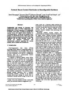
of routing switches located at the intersections of horizontal and vertical routing channels. Each CLB nests into a VersaBlock that provides local routing resources to connect between the CLB and GRM.
B. Xilinx Virtex E FPGA In this research work, the Virtex-E Field Programmable Gate Array has been used to implement the proposed simulink model and it is shown in Fig.3. It consists of two major configurable elements such as Configurable Logic Blocks (CLBs) and Input/Output Blocks (IOBs)[21]. CLBs and IOBs provide the functional elements for constructing logic and the interface between the package pins and the CLBs respectively. CLBs are interconnected through a General Routing Matrix (GRM), which comprises an array 564
International Journal of Computer Theory and Engineering, Vol. 1, No. 5, December, 2009
1793-8201
DLL DLL
Number of bonded IOBs
DLL DLL
Number of GCLKs
BRAMs
CLBs
BRAMs
CLBs
CLBs
CLBs
BRAMs
IOBs
VersaRing DLL DLL
252
31%
4
1
25%
It is seen from the Table I that the developed model for digital modulation identification utilizes 31% of bonded IOBs. It indicates that minimum of 252 IOBs needed for implementing the proposed algorithm. It may be seen from that the available Virtex are providing max of 248 [21]. The device utilization clearly indicates that the selected target device v3200efg1156 is well suited to implement the developed model. The summary of the timing report during the synthesis process is illustrated in Table II.
IOBs
BRAMs
VersaRing
804
DLL DLL Table II. Timing report for v3200efg1156 device
Figure 3 Virtex-E FPGA architecture
Parameter Minimum period Minimum input arrival time before clock Maximum output required time after clock Maximum combinational path delay
The VersaRing I/O interface provides additional routing resources around the periphery of the device. This routing improves I/O routability and facilitates pin locking. The Virtex-E architecture also includes dedicated block memories of 4096 bits each, clock DLLs for clock-distribution delay compensation, clock domain control and 3-State buffers associated with each CLB. Values stored in static memory cells control the configurable logic elements and interconnect resources. These values can be loaded into the memory cells on power-up, and it can be reloaded if change in the function of the device is necessary.
The Table II shows that the total time delay for the developed model is measured as 70.396ns (32.344ns for logic and 38.052ns for route) which has a percentage of 45.9% and 54.1% for logic and route respectively. Also observed that if the modulation changes, the time required to switch from one scheme to actual scheme is 70.396 ns. The total memory required to implement the proposed method has been observed as 714620 kilobytes. The technology level schematic for the generated model and the gate level schematic for a single block are shown in Fig 4 and 5 respectively. The technology level schematic is found to have higher complexity and can be reduced using the gate level schematic for the individual block. Hence the gate level schematic has been generated and analyzed for the all block. The performance of the synthesis has been analyzed after the gate level schematic analysis is carried out for entire block.
III. RESULT AND DISCUSSION The developed simulink model has been utilized to generate the VHDL code using Simulink HDL coder v1.4. After generating the VHDL code, the synthesis, place and route has been done using Xilinx ISE foundation series 10.1. The results obtained during the each process are explained in the following section. A. Synthesis output The first stage of the synthesis is to analyse the generated VHDL code to check the compatibility for synthesizing. After analyzing the source code, the target device has been synthesized and the netlist has been created. The device utilization summary for the target architecture of v3200efg1156 has been provided in Table I.
B. Outcome of Placing and Routing The synthesized netlist describes the interconnection of blocks, the logic cells within the blocks and the logic cell connections. The netlist is fed for floorplanning before placing and routing process. The floorplanning is the process that maps the logical description (netlist) with the physical description (floorplan).The main goal of the floorplanning is to arrange the block on a selected chip, decide the locations of I/O pads, power pads and clock distribution. The floorplanning for the proposed model has been generated and the top view of the same is illustrated in Fig. 6. It is observed form Fig. 6 that all the circuit elements are arranged at centre of the FPGA for the reported automatic digital modulation identification algorithm. After the floorplanning the logic cells within the flexible blocks have
Table I. Device utilization summary after synthesis
Name of blocks
% of Utilization
Available
Utilized
Number of Slices
32448
11135
Number of Slice Flip Flops
64896
1238
1%
Number of 4 input LUTs
64896
21080
32%
Duration (ns) 70.396 9.442 6.607 No path found
34%
565
International Journal of Computer Theory and Engineering, Vol. 1, No. 5, December, 2009
1793-8201 been placed and the necessary connection has been made by routing in a chip. The component organization for the proposed scheme after routing is shown in Fig. 7. The input, output ports and other related blocks as well as logic cells are interconnected using global routing method. The utilization of the target device has been estimated for the AMI system and the summary of the same is shown in Table III.
The Table III shows the implementation of the proposed method using the target device which utilizes less than 32 % of the slices and other blocks. It is also found that the area required to implement the proposed model for the target chip v3200efg1156 is 32.11% of the actual area which indicates the expansion possibilities for various demodulation schemes in future.
Figure 4 Technology Schematic of the developed hardware
566
International Journal of Computer Theory and Engineering, Vol. 1, No. 5, December, 2009
1793-8201
Figure 5 Gate level Schematic for a single block
Figure 6 Top view of floorplanning of the hardware
567
International Journal of Computer Theory and Engineering, Vol. 1, No. 5, December, 2009
1793-8201
Figure 7 Component organization of the AMI hardware after routing
D. Verification and validation of the reconfigurable hardware
C. Power utilization The power required for execution of modulation identification process using the target device v3200efg1156 has been computed and listed in Table IV for individual components. The total dynamic power for entire module has been calculated using the relation [21]. 10506 252 P= Pci + Pioj + Pclk (1) i =1 j =1 where P is Total Dynamic Power Pci is the power of ith Component Pioj is the power of jth IO pad Pclk is Clock power
∑
∑
The total power required to implement the proposed method is the combination of quiescent power and dynamic power. It is seen from the Table IV that the total power required to implement the proposed module in Virtex-E v3200efg1156 is 466 mW.
Verification of the hardware The implemented AMI reconfigurable digital modulation identifier has been verified and validated for different digital modulation schemes such as BPSK, QPSK, 8PSK, 16PSK, 2QAM, 4QAM, 8QAM, 16QAM, 2FSK, 4FSK, 8FSK, 16FSK and GMSK. For example, the generated model has been verified for above modulation schemes and the test output is shown in Fig 8. The simulation result shows that the module produces low output (not identified) when reset is low and it produces high output (identified) when reset is high. The developed module has been tested for various modulation schemes under AWGN noisy environment for different SNR. The verification and validation of the proposed model has been carryout for different digital modulation scheme and genuiness of the implemented hardware has been analyzed. The percentage of correct identification of the proposed AMI hardware at 3 dB SNR has been estimated and shown in Table V.
Table IV Power required for the target device
Name Clocks IOs Logic Signal Total Quiescent Power Total Dynamic Power Total Power
Power (W) 0.000 0.000 0.082 0.017
Quantity Available
Quantity Used
808 64896
1 252 19825 28890
Utilization (%)
Table V Percentage of identification of the proposed AMI hardware at 3 dB SNR
Modulation Scheme 2FSK 4FSK 8FSK 16FSK GMSK BPSK QPSK 8PSK 16PSK 2QAM 4QAM 8QAM
31.2 30.5
0.367
0.099 0.466
568
% of identification 100 99.4 98.9 98.6 99.1 98.6 97.8 97.5 98.2 100 98.4 97.6
International Journal of Computer Theory and Engineering, Vol. 1, No. 5, December, 2009
1793-8201 16QAM
[5]
98.2
It is seen from table V that the proposed AMI hardware identifies the most of the digital modulation schemes even at 3 dB SNR with 97.5% of correct identification.
[6]
[7]
Testing At initial condition, the state of the FPGA has been maintained in predetermined position and whenever the modulation changes in the received signal, the FPGA is reconfigured by downloading the appropriate bit stream file. Also observed that if the modulation changes from one scheme to other, it has been measured that the time required to respond the developed hardware is 70.396 ns. Various bit files have been are generated for different modulation schemes. The modulation identifier in the FPGA monitors the input signal to determine the modulation type when input signal changes between two decision intervals which reconfigure the hardware. It is also ensured that the reconfiguration take place only at the end of the decision interval to avoid the misfiring of the hardware. IV. CONCLUSION
[8]
[9]
[10]
[11]
[12]
[13]
The FPGA implementation of the Automatic Modulation Identification (AMI) module for Software Defined Radio has been implemented. The algorithm was developed using Matlab/Simulink and implemented using Xilinx Virtex-E v3200efg1156 FPGA device. The implemented hardware has been verified and validated for different digital modulation schemes and the results show that the module can identify most of the digital modulation schemes with signals having lower bound of 3 dB SNR.
[14] [15]
[16]
[17] [18]
REFERENCES [1] [2]
[3]
[4]
J. H. Reed, “Software Radio A Modern Approach to Radio Engineering,” Prentice Hall, Upper Saddle River, NJ, 2002. Polydoros, J. Rautio, G. Razzano, H. Bogucka, D.Ragazzi, P. I. Dallas, A. Mämmelä, M. Benedix, M.Lobeira and L. Agarossi.:, “WIND-FLEX: Developing a Novel Testbed for Exploring Flexible Radio Concepts in an Indoor Environment,” IEEE Comms. Mag, vol. 41, July 2003, pp.116-122,. H. Harada, Y. Kamio and M. Fujise., “Multimode Software Radio System by Parameter Controlled and Telecommunication Component Block Embedded Digital Signal Processing Hardware,” IEICE Trans. Communication., vol. E83-B, June 2000, pp.1217-1228. Shinji Ohara, Masato Kita, Ikuo Oka and Shingo Ata, “Modulation Classification Based on Amplitude and Cosine moments,” IEICE Tech. Rep., vol. 108, March 2009, pp.105-108.
[19]
[20]
[21]
569
David Asano and Mao Ohara, “Automatic Modulation Identification Using a Frequency Discriminator,” IEICE Transactions on Communications, vol. E91-B(2), June 2008, pp. 575-578. Jian Chen, Yonghong Kuo, Fenglin Fu, Chao Li and Jiandong Li, “Digital Modulation Identification Based on Software Radio Platform,” Proc. Sixth Intl. conf. on Parallel and Distributed Computing Applications and Technologies, 2005, pp. 945-949. Lu Man-jun, Zhan Yi, Si Xi-cai and Yang Xiao-niu, “Blind identification of digital communication signals based on statistics of directional data,” Proc. Intl. Conf. on Advanced Infocomm Technology, 2008, Article No. 26. Ataollah Abrahamzadeh, Seyed Alireza Seyedin and Mehdi Dehghan, “Digital-signal-type identification using an efficient identifier,” EURASIP Journal on Applied Signal Processing, vol. 2007, January 2007, pp. 63 – 63. E. Avci and D. Avci, “The performance comparison of discrete wavelet neural network and discrete wavelet adaptive network based fuzzy inference system for digital modulation recognition,” Expert Systems with Applications: An International Journal, vol. 35, July 2008, pp. 90-101. J. Palicot and C. Roland., “FFT: a Basic Function for a Reconfigurable Receiver,” Proc.10th Int. Conf. on Telecommunications, Feb. 2003, pp. 898-902. R. Srikanteswara, R. Chembil Palat, J. H. Reed and P. Athanas., “An Overview of Configurable Computing Machines for Software Radio Handsets,” IEEE communication Magazine, vol. 41, July 2003, pp.134-141. R. Hartenstein, “A decade of reconfigurable computing: a visionary retrospective,” Proc. Int. Conf. and Exhibition on Design, Automation and Test in Europe, 2001, pp. 642- 649. M. Cummings and S. Haruyama., “FPGA in the Software Radio,” IEEE Communication Magazine, vol. 37, Feb. 1999, pp. 108- 112. Enrico Buracchini, “The Software Radio Concept,” IEEE Communication Magazine, vol. 38, September 2000, pp. 138-143. Jun-Seo Lee, Jong-Hyun Park, Sang-Woo Kim,YingShan Li and Heung-Gyoon Ryu., “Implementation of DSP-Based Digital Receiver for the SDR Application,” Proc. l0th Asia-Pacific Conf. on Communications and 5th Int. Symposium on Mu1ti-Dimensional Mobile Communications, 2004 pp 06-10. John glossner, Daniel lancu, jinlu, erdens hokenede and Mayan moudgill., “A software –defined Communications baseband design,” IEEE Communication Magazine, vol. 41, January 2003, pp.120-128. Jason Molby, “JTRS and the evaluation toward software defined radio,” IEEE Personal Communication, 2002, pp. 1286-1290. Huie. J, D'Antonio. P, Pelt. R and Jentz. B., “Synthesizing FPGA Cores for Software Defined Radio General Dynamics Decision Systems,” Software Defined Radio Technical Conference and Product Exposition, November 2003. P.Prakasam and M.Madheswaran, “Intelligent Decision Making System for Digital Modulation Scheme Classification in Software Radio Using Wavelet Transform and Higher Order Statistical Moments,” Wireless Personal Communications: An International Journal, doi: 10.1007/s11277-008-9621-z. P. Prakasam and M.Madheswaran, “Digital Modulation Identification Model Using Wavelet Transform and Statistical Parameters,” Journal of Computer Systems, Networks and Communications, 8 pages, doi:10.1155/2008/175236. http://www.xilinx.com/products
International Journal of Computer Theory and Engineering, Vol. 1, No. 5, December, 2009
1793-8201
Figure 8 Verification output of the proposed model
Table III. Summary of device utilization after place and route process Name of blocks
Available
% of Utilization
Utilized
Number of GCLKs
4
1
25%
Number of External GCLKIOBs
4
1
25%
Number of LOCed GCLKIOBs
1
0
0%
Number of External IOBs
804
251
31%
Number of LOCed IOBs
251
0
0%
Number of Slices
32448
10506
32%
Overall
33512
10759
32.11%
P. Prakasam has born on May 09 1973 and he obtained his BE degree in Electronics and Communication Engineering from Madras University in 1994. He received his M.Tech degree in Advanced Communication Systems from Sastra Deemed University, Tanjore, India. Currently he is doing his Ph.D at Anna University, Chennai, India in Signal Processing in Communication Systems He is working in Maha Barathi Engineering College, Chinnasalem, India, as a Professor in the Department of Electronics and Communication Engineering. Presently he is involved in developing a generalized modulation identification algorithm for adaptive demodulator in software defined radio. He has published more than fifteen research papers in national and international conferences/journals. His special areas of interest are Signal Processing, Communication Systems and Applications of signal processing in Mobile Communication Systems. Mr.P. Prakasam is a member of IEEE (USA), senior member of IACSIT, life member of ISTE, and VSI (India). He has also coordinated Conferences, AICTE and ISTE sponsored SDP and STTP programme organized by the Department.
M. Madheswaran has born on July 10, 1968 and he received the BE Degree from Madurai Kamaraj University in 1990, ME Degree from Birla Institute of Technology, Mesra, Ranchi, India in 1992, both in Electronics and Communication Engineering. He obtained his PhD degree in Electronics Engineering from the Institute of Technology, Banaras Hindu University, Varanasi, India, in 1999. At present he is a Principal of Muthayammal Engineering College, Rasipuram, India. He has authored over sixty research publications in international and national journals and conferences. His areas of interest are theoretical modeling and simulation of high-speed semiconductor devices for integrated optoelectronics application, Bio-optics and Bio-signal Processing. Dr.M.Madheswaran was awarded the Young Scientist Fellowship (YSF) by the State Council for Science and Technology, TamilNadu, in 1994 and Senior Research Fellowship (SRF) by the Council of Scientific and Industrial Research (CSIR), Government of India in 1996. Also he has received YSF from SERC, Department of Science and Technology, Govt. of India. He is named in Marquis Who’s Who in Science and Engineering in the year 2006. He is a Chairman of IEEE India EDS Chapter and Vice-chairman of IEEE India SSCS Chapter. He is a life member of IETE, senior member of IACSIT,ISTE and IE (India) and also a senior member of IEEE.
570