applied sciences Article
Reduction of Liquid Bridge Force for 3D Microstructure Measurements Hiroshi Murakami 1, *, Akio Katsuki 2 , Takao Sajima 2 and Mitsuyoshi Fukuda 1 1
2
*
Department of Mechanical Systems Engineering, Faculty of Environmental Engineering, The University of Kitakyushu, 1-1 Hibikino, Wakamatsu-ku, Kitakyushu, Fukuoka 808-0135, Japan;
[email protected] Department of Mechanical Engineering, Faculty of Engineering, Kyushu University, 744, Motooka, Nishi-ku, Fukuoka 819-0395, Japan;
[email protected] (A.K.);
[email protected] (T.S.) Correspondence:
[email protected]; Tel.: +81-93-695-3201
Academic Editor: Kuang-Cha Fan Received: 14 April 2016; Accepted: 11 May 2016; Published: 16 May 2016
Abstract: Recent years have witnessed an increased demand for a method for precise measurement of the microstructures of mechanical microparts, microelectromechanical systems, micromolds, optical devices, microholes, etc. This paper presents a measurement system for three-dimensional (3D) microstructures that use an optical fiber probe. This probe consists of a stylus shaft with a diameter of 2.5 µm and a glass ball with a diameter of 5 µm attached to the stylus tip. In this study, the measurement system, placed in a vacuum vessel, is constructed suitably to prevent adhesion of the stylus tip to the measured surface caused by the surface force resulting from the van der Waals force, electrostatic force, and liquid bridge force. First, these surface forces are analyzed with the aim of investigating the causes of adhesion. Subsequently, the effects of pressure inside the vacuum vessel on surface forces are evaluated. As a result, it is found that the surface force is 0.13 µN when the pressure inside the vacuum vessel is 350 Pa. This effect is equivalent to a 60% reduction in the surface force in the atmosphere. Keywords: surface force; van der Waals force; electrostatic force; liquid bridge force; microstructure; measurement; optical fiber probe; laser diode; coordinate measuring machine (CMM)
1. Introduction Recent years have witnessed an increased demand for a method for precise measurement of the microstructures of mechanical microparts, microelectromechanical systems, micromolds, optical devices, microholes, etc. However, precise measurement of the shape of a microstructure with a large length-to-diameter (L/D) ratio is rather difficult because of the difficulty in probe fabrication and sensing methods where the measuring force is very small. Previous works have reported microstructure measurement techniques that employ a variety of probes such as optical probes, vibroscanning probes, vibrating probes, tunneling effect probes, opto-tactile probes, fiber deflection probes, optical trapping probes, and diaphragm probes [1–9]. In a previous study, we developed a system for the measurement of three-dimensional (3D) microstructures using an optical fiber probe that functions as a kind of displacement measuring probe with a small contact force and wide measurement range [10]. In this system, the shaft of the stylus does not need to be rigid for the detection of the measuring force, because the deflection of the stylus is measured by a non-contact method. In general, when the particle size is less than several tens of micrometers, the effects of surface force generated from the van der Waals force, electrostatic force, and liquid bridge force are strengthened and this surface force becomes greater than the force of gravity [11]. We used a fiber stylus with a 5-µm-diameter sphere on its tip, and as a result, we found
Appl. Sci. 2016, 6, 153; doi:10.3390/app6050153
www.mdpi.com/journal/applsci
is scanned continuously in the scanning mode (Figure 1b), the measurement accuracy reduces because of the bending of the stylus shaft due to the adhesion. The observed adhesion, which is influenced by environmental factors (e.g., humidity) and the roughness of the measurement surface, is not reproducible. Therefore, in another previous work, we developed a measurement system for 3D microstructures that uses a vibrating fiber probe (Figure 1c) to prevent adhesion of the stylus tip Appl. Sci. 2016, 6, 153 2 of 11 to the surface being measured [12]. In this system, the stylus tip is set to vibrate in a circular motion, where it traces a circle of diameter 0.4 μm in the X‐Y plane. However, the stylus tip actually traces an that the measurement surface draws the stylus tip closer when the tip approaches it and the distance elliptical path. The difference between the profile of the perfect circle and that of the actual elliptical between the stylus stylus tip tip and the surface is less than thethe regular displacement. When the path of the leads to measured measurement error. Moreover, surface roughness cannot be stylus tip comes into contact with the measured surface, it adheres to the surface and cannot be measured in the scanning mode when using the vibrating fiber probe. separated it. When the measured surface is scanned point by point theeffects touch-trigger mode In the from present study, the stylus characteristics are examined. Then, in the of the surface (Figure 1a), the measurement time increases because the stylus tip is required to be separated from the force on the adhesion are analyzed. The results confirm that the primary cause of adhesion is the measured surface to overcome the surface force. When the measured surface is scanned continuously liquid bridge force. Therefore, the measurement system, placed in a vacuum vessel, is constructed in the scanning mode (Figure 1b), the measurement accuracy reduces because of the bending of the suitably to prevent the adhesion caused by the surface force between the stylus tip and the measured stylus shaft to the The observed adhesion, which is influenced by environmental surface. The due effects of adhesion. pressure inside the vacuum vessel on the surface force are evaluated factors (e.g., humidity) and the roughness of the measurement surface, is not reproducible. Therefore, experimentally. The surface force is calculated by assuming that the optical fiber probe is equal to in another previous work, we developed a measurement system for 3D microstructures that uses a the cantilever of the fixed support. In other words, the surface force is calculated by the deflection of vibrating fiber probe (Figure 1c) to prevent adhesion of the stylus tip to the surface being measured [12]. the stylus shaft. There are many techniques for measuring surface forces, such as those involving the In this system, stylus tip is setatomic to vibrate in amicroscopy circular motion, where it traces a circle of diameter surface forces the apparatus (SFA), force (AFM), micro cantilever (MC), optical 0.4 µm in the X-Y plane. However, the stylus tip actually traces an elliptical path. The difference trapping (OT), etc. [13–15]. The measuring method that uses the optical fiber probe is, in principle, between the profile of the perfect circle and that of the actual elliptical path of the stylus tip leads to similar to the SFA and AFM. As a result, the surface force is found to be 0.13 μN when the pressure measurement error. Moreover, the surface roughness cannot be measured in the scanning mode when inside the vacuum vessel is 350 Pa. This effect is equivalent to a 60% reduction in the surface force in using the vibrating fiber probe. the atmosphere.
Stylus tip Measured surface
Z
Z
X
X
(a)
(b)
Stylus tip
Y
Z
X Circular motion
X
(c)
Figure 1. ofof probes. (a)(a) Touch-trigger probe; (b) scanning probe; and (c) vibrating probe Figure 1. Various Various types types probes. Touch‐trigger probe, (b) scanning probe, and (c) vibrating (touch-trigger mode). probe (touch‐trigger mode).
In the present study, the stylus characteristics are examined. Then, the effects of the surface force on the adhesion are analyzed. The results confirm that the primary cause of adhesion is the liquid bridge force. Therefore, the measurement system, placed in a vacuum vessel, is constructed suitably to prevent the adhesion caused by the surface force between the stylus tip and the measured surface. The effects of pressure inside the vacuum vessel on the surface force are evaluated experimentally. The surface force is calculated by assuming that the optical fiber probe is equal to the cantilever of the fixed support. In other words, the surface force is calculated by the deflection of the stylus shaft. There are many techniques for measuring surface forces, such as those involving the surface forces apparatus (SFA), atomic force microscopy (AFM), micro cantilever (MC), optical trapping (OT), etc. [13–15]. The measuring method that uses the optical fiber probe is, in principle, similar to the SFA
Appl. Sci. 2016, 6, 153
3 of 11
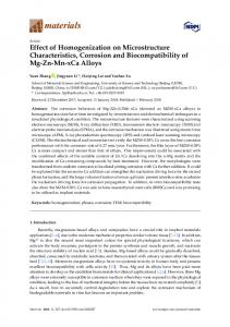
and AFM. As a result, the surface force is found to be 0.13 µN when the pressure inside the vacuum vessel is 350 Pa. This effect is equivalent to a 60% reduction in the surface force in the atmosphere. 2. Measurement Principle Figure 2 shows a diagram of the developed optical measurement system. The stylus consists of a 2.5-µm-diameter optical fiber to which a 5-µm-diameter glass stylus tip is attached. The total length of the stylus is 0.38 mm. The probing system consists of the fiber stylus, two laser diodes with a 650 nm wavelength (LDX and LDY in the X- and Y-directions, respectively), and two dual-element photodiodes (PX and PY in the X- and Y-directions, respectively). The stylus shaft is fixed to a tube-type piezo driver element in order to perform attitude adjustment of the stylus shaft; the stylus shaft is installed between the laser diodes and the dual-element photodiodes, which are oriented orthogonally. The laser diodes are mounted above the stylus tip, and the focused laser beams irradiate along the X- and Y-directions onto the stylus shaft. The two dual-element photodiodes are located opposite the laser diodes beyond the stylus. The laser beams that pass through the stylus shaft are received by these dual-element photodiodes. The beam intensities detected by the photodiodes are converted into voltages; hereafter, these intensities are denoted as IPX1 , IPX2 , IPY1 , and IPY2 (V). The output signal IX in the X-direction obtained using IPY1 and IPY2 and the output signal IY in the Y-direction obtained using IPX1 and IPX2 are defined as given in Equations (1) and (2), respectively. A charge-coupled device is employed to monitor the positions of the stylus and test piece during the setting up of the equipment and the measurement. IX “ IPY1 ´ IPY2 (1) IY “ IPX1 ´ IPX2
Appl. Sci. 2016, 6, 153
(2) 4 of 11
Figure 2. Measurement system using optical fiber probe. Figure 2. Measurement system using optical fiber probe. I PY2 I PY1
I a cross-sectional I = To illustrate = the measurement principle of theI optical fiber probe, Figure 3 shows IPY2 ), as shown in Figure 3b. When the stylus I Dual-element photodiode shaft is displaced in the +X-direction, the angle of refraction of the laser beam passing through the Movement direction Condenser len s stylus shaft in the Y-direction changes owing to a shift in the part of the stylus shaft being irradiated. Additionally, when the stylus tip comes into contact with the measured surface in the Y-direction, the light intensities measured by each element of the dual-element photodiode are no longer equal to each (a) (b) (c) other (i.e., IPX1 < IPX2 and IPY1 = IPY2 ), as shown in Figure 3c. As a result, the contact direction and RY1
RY2
RY1
RX2
=
=
PX2
PX1
R X1
RX 2