Jul 30, 2013 - Pierre-Frédéric Villard, Vincent Baudet, Michaël Beuve, Behzad Shariat,. Fabrice Jaillet. To cite this version: Pierre-Frédéric Villard, Vincent ...
Resolution of Non-Linear Problems In Realistic-Lung-Inflating Simulation with Finite Element Method. Pierre-Fr´ed´eric Villard, Vincent Baudet, Micha¨el Beuve, Behzad Shariat, Fabrice Jaillet
To cite this version: Pierre-Fr´ed´eric Villard, Vincent Baudet, Micha¨el Beuve, Behzad Shariat, Fabrice Jaillet. Resolution of Non-Linear Problems In Realistic-Lung-Inflating Simulation with Finite Element Method.. 10th workshop on Heavy Charged Particles in Biology and Medicine. Oropa (Italy), 2005, Oropa, Italy. pp.184–187, 2005.
HAL Id: hal-00849205 https://hal.inria.fr/hal-00849205 Submitted on 30 Jul 2013
HAL is a multi-disciplinary open access archive for the deposit and dissemination of scientific research documents, whether they are published or not. The documents may come from teaching and research institutions in France or abroad, or from public or private research centers.
L’archive ouverte pluridisciplinaire HAL, est destin´ee au d´epˆot et `a la diffusion de documents scientifiques de niveau recherche, publi´es ou non, ´emanant des ´etablissements d’enseignement et de recherche fran¸cais ou ´etrangers, des laboratoires publics ou priv´es.
RESOLUTION OF NON-LINEAR PROBLEMS IN REALISTIC-LUNG-INFLATING SIMULATION WITH FINITE ELEMENT METHOD P-F. Villard, V. Baudet, M. Beuve, B. Shariat and F. Jaillet LIRIS, Villeurbanne (FRANCE) Abstract Hadrontherapy treatment needs accurate tumour targeting, which is difficult for lung cancer due to breathing motions. We propose to quantify lung deformation and displacement by a simulation technique based on the geometrical and mechanical properties of organs. Thereby, we model lung behaviour by a 3D dynamic deformable model derived from continuous mechanics, computed with finite elements method (FEM).
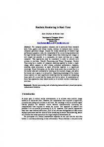
1. INTRODUCTION Hadrontherapy is an efficient technique to cure local cancerous tumours. However, it needs accurate targeting necessitating a precise knowledge of the shape and position of tumours. Concerning the lung cancer, breathing motion is a crucial problem for variety of tumours. A current important progress would be tumour motion prediction. In this paper we propose to model lung inflating in the framework of continuous mechanics. The computation is carried out by FEM, which implies non-linearity such as stiffness evolution according to displacement, namely large deformation problem and boundary conditions, namely contact with surrounding obstacles. Here the aim is to solve such kind of problems and to properly determine the numerical parameters. 2. OUR APPROACH Thorax (Figure 1) is the highest part of the trunk, which extends from the base of the neck to the diaphragm. Lungs are wrapped in a fibrous membrane: the pleura, containing a lubricating fluid which allows slipping. The pressure in the cavity is below the atmospheric pressure, making tissues remain in contact. Diaphragmatic and rib-cagemuscle actions cause pressure changes inside the pleura, and consequently steadily induce lung inflation or deflation. Figure 1. Thorax anatomy
We base our simulation on continuous mechanics formalism and we modelise as precisely as possible the pleura behaviour: 1- The whole system is fixed to the trachea. 2A uniform negative pressure is applied around the lung at its initial surface. 3- Lung inflates until its surface matches its boundary surface (cf Figure 1). 4- Surface sliding without friction (as pleura does) is allowed. It means that we do not search a point to point matching but a surface to surface matching between two states. 3. NON-LINEARITY PROBLEMS 3.1 FEM RESOLUTION In a global approach, and as a first approximation, a homogeneous model is used to parameterise lung inflation. The FEM [4] is a numerical method that consists in approaching the solution by a simple expression based on the discretisation of the space
into small elements. In our case it consists in searching displacements U to reduce as possible the residue R defined by: R(U ) = F − K(U ).U
(1)
where K is the stiffness matrix and F is the load vector. In the case of small strains, K(U ) can be approximated by K0 . Then F is linear with U : F = K0 U . However for large strains strong modifications in shape of the stretched material do not allow such simple assumption. F = K(U )U is no longer linear. The full non-linear system is solved with the iterative Newton-Raphson algorithm giving (Un ) by: (
K(Un−1 ).∆Un − R(Un−1 ) = 0 ∆Un = Un − Un−1
(2)
3.2 MESHING An experimental protocol provides us with thoracic CT scan examinations. During a CT-scan, organs can move and introduce artifacts. To reduce these uncertainties, we record the CT scan examination by determining a position of the respiratory cycle and by blocking the breathing on this position (ABC). To extract lung surface, we segment CT scan sections of the right and left lungs and of the surrounding organs. Practically, the anatomic volumes are meshed with a set of small volume elements. The convergence rate directly depends on mesh accuracy. We have presented in [3], a convenient method to generate a lung mesh. We divided the mesh into three entities: triangles, tetrahedra and hexahedra. 3.3 LARGE-STRAIN PROBLEM Commonly, lung volume can increase by a factor of two during a typical respiration cycle. Large strains have then to be considered. Therefore, we employ the expressions presented in [2]. This method uses the Cauchy-Green strain tensor ǫcg computed with the transformation gradient G of the geometrical deformation: ǫcg = 1/2(Id − (G.GT )−1 )
(3)
The stress tensor used is the Kirchoff tensor τ (Xf ), computed as a ”scaling” of the tensor σ(Xi ): τ (Xf ) = det(G).σ(Xi ) (4) where σ(Xi ) is the state of stress at the position Xi . K(Un−1 ) is then evaluated with (3) and (4) and therefore is non-linear, then the residue R(un−1 ) is estimated according to (1), which gives Un from (2). 3.4 CONTACT PROBLEM We propose the following process to handle contact conditions:
- Couples of points P and M potentially in contact are searched. - Distance P M must be positive to satisfy the conditions of non penetration i.e.: P Mn−1 .N + (UM − UP ).N ≤ 0. - The equilibrium equation must be completed by a force to add compression and avoid a physical separation. This is the second source of non-linearity.
- An equation must be added to express that this force takes part only when contact is reached and only corresponds to a compression force. If the imposed negative pressure is not sufficiently important, residue R of equation (1) will be reached before contact condition. The pressure value must then be large enough. The Newton-Raphson iterations are stopped when a fixed residue is reached. Simply applied to a problem with contact condition the results are not satisfactory. Convergence is then ensured by sub-iterations taking into account geometry reactualisations. 4. NUMERICAL EXPERIMENTS 4.1 EXPERIMENTAL PARAMETERS The mechanical parameters are the following : first geometry is extracted from the same patient, characterised by 10778 points and 30097 elements. Lung bounding box dimensions are 240 mm × 180 mm × 245 mm. An example of a patient’s compliance C has been measured here to be C = 3.5 l/kP a, initial volume of the studied lung is Vi = 3.6 l and its final volume is Vf = 3.8 l. According to compliance law recoil, pressure needed for a correct inflating of Vf − Vi is given by: dP = −dV = 3.8−3.6 = 57 P a. To apply a C 3.5 sufficiently large negative pressure as seen in §3.4, we set P = 60 P a. Patient compliance = 823P a. C = 3.5 l/kP a with initial volume Vi = 3.6 l and ν = 0.3 gives E = 2 Vi (1−2ν) C Convergence parameters have also been determined. Minimum residue of equation 2 is set to R = 10−6 and the maximum iteration number is set to 99. Computation of lung motion have been calculated with several number of geometry reactualisation for the contact conditions. Experiments are summarised in the Table 1. Between two experiments, differences in displacement vectors are analysed: for each node of both simulations, we compute the norm of each displacement vector. We calculated the average and the standard deviation. After a series of tests with iteration number running from 1 to 7. We observed that a correct convergence can be obtained after 5 iterations (see Table 1) while error is lower than 2%.
Table 1. Stabilisation vs iteration number Reactualisation number 1 3 5 7
Computing time 14h43m 15h15m 15h28m 15h48m
Average displacements 5.66 mm 5.23 mm 5.1 mm 5.1 mm
4.2 DEFORMATION RESULTS Our numerical simulations were carried out with the code-aster [1] finite element software. The tests have been realised on a Pentium 4, 2.40GH with 1GB memory.
In accordance with trial assumption defined in §2., the final surface matches well with geometry extracted from CT scans. There is no convergence problem associated to mesh aberration and the obtained displacement field is totally smooth. CONCLUSION We proposed here a model of lung inflation based on continuous mechanics and considering global properties for the lung. During equation resolution with finite elements method we observed the crucial importance of meshing. In this paper, we ended the validation of our meshing methodology and performed tests of convergence that ensure the stability of our code. To be useful for physicians, our model will be soon converted into a 3D + time CT scan. Then, comparing our simulated CT scan with the reality, we will add more details in our simulation (heterogeneity, ...), if necessary for hadrontherapy accuracy. At the same time, dosimetry will be included into our model with respect to hadron physical laws.
References [1] Code Aster. http://www.code-aster.org/. [2] J.C. Simo and C. Miehe. Associative coupled thermoplasticity at finite strains: formulation, numerical analysis and implementation, Comp. Meth. Appl. Mech. Eng., 98:41–104, (1992). [3] P-F. Villard, M. Beuve, B. Shariat, V. Baudet, and F. Jaillet. Lung Mesh Generation to Simulate Breathing Motion with a Finite Element Method, IEEE, Mediviz, Conference on Information Visualization:194–199, (2004). [4] O.C. Zienkiewicz and R.L. Taylor. worth/Heinemann, (2000).
The Finite Element Method.
Butter-