Jul 28, 1997 - e-mail: [ sp/zedan/luker]@dmu.ac.uk. Abstract ..... clustered into a library class, which is declared as public and static indicating that there is no ...
Resource Usage Matrix in Object Identification and Design Transformation of Legacy Procedural Software
Sagar Pidaparthi, Hussein Zedan, Paul Luker School of Computing Sciences, DeMontfort University, Leicester, UK, e-mail: [ sp/zedan/luker]@dmu.ac.uk
Abstract
This paper provides a novel technique for object identification from legacy procedural software, which can also be applied in partitioning of classes in object oriented software systems. Currently there is a movement towards object oriented design and programming, from algorithmic decomposition, structured design and procedural implementation. It is more economic to restructure existing software into object oriented topology by identifying objects within the subject system than to redesign software starting from requirements. Such object identification relies upon program analysis and a study of inter component relationships. This paper initially provides a conceptual foundation for migration from procedural to object oriented software architecture for legacy software. It relies upon a view of software life cycle, in which all software development is considered to be evolutionary activity with re-engineering/restructuring as an important process applied repeatedly on the artefacts of development at various stages in this evolution. Secondly, it introduces a novel approach of viewing a procedural program from an object oriented perspective in which there is a single god class which has a large number of global variables & methods, supported by several user defined classes which have no behaviour but data definitions. This view, coupled with repeated restructuring, enables a seamless migration of behaviour from the god class to other classes using design transformation methods. This paper distinguishes between the processes of translation and transformation and states that these two are orthogonal to each other, thus enabling us to concentrate on design transformations to migrate from one design to another, leaving the language issues to be handled by translators. It describes some basic design transformations which permit partitioning of classes while preserving the system behaviour, enabling a series of heuristics to be used in conjunction with design transforms to migrate to a better software structure. The main contribution of this paper is in the proposal of a new algorithm for object identification called resource usage matrix, a visualisation of resource usage within the system for object identification. A case study in object identification is presented to highlight the usefulness of resource usage matrix in object identification.
1. Introduction Software design and development is a complex process for which several methodologies have been developed to address this complexity. In the early 1970s stepwise refinement and algorithmic decomposition were used for software development, which resulted in structured techniques. This kind of action oriented decomposition leads to centralised control mechanisms while the more modern object-oriented decomposition leads to decentralised software architectures. This paper demonstrates that it is possible to migrate from procedural legacy software decomposed using algorithmic methods to object-oriented structures using reverse engineering followed by restructuring of software systems. During this process, the software can be translated into an object-oriented programming language like Java, however it is important to note that this kind of translation is orthogonal to the design transformation which is the key to the migration process.
Submitted to 14th Automatic Software Engineering Conference Length to be reduced to about 9 Pages. printed on 28/07/97 09:31:30
Chikofsky and Cross[1] define reverse engineering as the "process of analysing a subject system to identify the system's components and their inter-relationships, to create representations of the system in another or at higher level of abstraction". RESTRUCT is a project which uses reverse engineering to transform poorly structured programs into programs with object-oriented structure. An object in a conventional programming language can be defined as a collection of routines, types and data items[2]. The routines implement the methods associated with objects; types represent object attributes, and data items represent or point to actual instances of the object classes. Finding and defining such objects is a natural way to create a representation of the system in another form and in a higher level of abstraction. Sneed[3] describes 10 steps to deriving object-oriented design from program structure. RESTRUCT is a CASE tool which works on Sneed's third step, which defines objects in three ways which are based on the algorithms proposed by Livadas & Roy[2] and Liu & Wilde[4], these are global based, type based and receiver based object identifiers. In this tool a relational database is used to store information about subject program structure. Object identification algorithms use the information from the database to restructure the program and to store the new structure in the database. The new program structure information can be used to synthesise the object-oriented source code. In section two we discuss the nature of software and its evolution concentrating on design evolution and restructuring, for which we introduce the concepts of black box and glass box representations of design and black box and glass box transformations. This is followed by a discussion on translation and how it differs from transformation of design. The fourth section presents a novel and a unique view of a procedural program, in which we view a procedural program to be a badly structured object-oriented program which has a god class with global variables and methods and several user defined classes with data members and little functionality. Following on from this, some basic design transformations are discussed, which permit partitioning of classes. This is followed by some object identification heuristics and a discussion of a case study undertaken using RESTRUCT tool developed using the ideas presented in this paper.
2. Related Work Software Design and development is evolutionary in its nature, which starts from its very first phases. Structured methodologies of the 70s and 80s advocated linear design processes which were unrealistic in their approach. It is now accepted that software design and development requires cyclic or iterative approaches. Booch[5] proposes a life cycle in which there are two kinds of processes for software design, one of which is the macro design process and the second being the micro design process. Each phase in the macro design process has a complete iteration of a micro design processes. From this and the other contemporary life cycles it is possible for us to infer that artefacts of design are repeatedly subjected to review/restructuring. Artefacts of early analysis and design lack detail and are very often black box representations. As the design cycle progresses, detail or glass box representation is added to the system. The main artefact of this process is design which is refined using transformations and embellished by adding detail to produce a program. To understand the evolution, we need to define design, black box representation, glass box representation, black box (design) transformation and glass box transformation. Design of a software system can be viewed as organisation of software components in a program. Design is a hierarchically structured and component-wise specified software system[6,7,8]. Each component has a specification and an optional implementation. Usually there is one component which is called the system, which represents the system to be developed. Components in a software system are: classes, procedures, functions, types, variables. Design can be developed using design languages, which can be graphical like OMT[9], UML[10], or Booch[5] notation or by using languages like Language for Object-Oriented Modelling (LOOM)[11], alternatively they can be specified using formal languages like COLD-K[7,8] as in the Meteor Project. The authors of OMT, UML, and LOOM concentrated on design representation and do not discuss design transformations, whereas Meteor[6,7,8] project works on design transformation using formal languages and provides formal proofs for behavioural equivalence in design transformation. However, it is important to note that the design transformations discussed by Feijs [6], are at a very high level of abstraction and are not suitable for our purpose of migration from procedural to object-oriented programs. The Meteor project defines a design language COLD-K to specify the designs of software systems, in which it introduces the concepts of black box descriptions and glass box descriptions of software systems. A Black box description provides interface specification, whereas the glass box description provides the details of a system component. Certain components are primitives and do not have the glass box descriptions. It is now possible to define two notions of correctness for design i.e. the black box correctness of a design and the glass box correctness of a design. The black box correctness is based on the principle that no details of the implementation module be known when using the modules. The user must rely entirely on interface specifications i.e. the black box description. It is essential that the user of an interface should not have to know anything about the details of implementation. In particular, the fact that this interface may be formed by a single body or a set of several bodies should not make any difference. Black box
Submitted to 14th Automatic Software Engineering Conference Length to be reduced to about 9 Pages. printed on 28/07/97 09:31:30
descriptions have been formalised using mathematical logic, in the Meteor project. Thus a design is built up from components and the correctness of a complete design follows from correctness of its components. When modifying one component, the correctness of the resulting design follows from the correctness of modified component. Software transformation can take place atleast at two levels, i.e. at black box level and at glass box level while preserving semantics of a system. When a component retains its blackbox semantics but is modified at the glassbox level, then it is sufficient to ensure local correctness of the component to prove the semantic equivalence of initial and modified systems. When a design i.e. black box transformation is performed it is sufficient to prove the equivalence at black box level. In practical applications to represent a design there are two possibilities. The first possibility is to have a design engineering database with operations among which yields the glass box description and blackbox descriptions of a component. The second possibility is to include the notion of a component in a design language. In RESTRUCT we adopt the first approach as it provides an easy mechanism to search and analyse the relationship between components. The database structures [13-16] described in the literature on program analysis forms the backbone for the design of our CASE tool database and is reported in Pidaparthi & Cysewski[17,18]. The reported literature on migration does not provide adequate answers to some important questions listed below: a) What is the relationship between Design transformation and program translation? b) How is the paradigm shift from procedural programming to object-oriented programming addressed for the migration of a system from procedural structure to object-oriented structure? c) What are the basic transforms required for migration from procedural design to an object-oriented design? d) How good are the object identification algorithms reported in the literature? e) What is the quality of an object-oriented system obtained by design transformation? How it compare with that of a system designed starting from requirements using object-oriented analysis techniques. The main contribution of this paper is in providing the answers to the first three of these questions and we aim to provide the answers to the remaining question in the near future.
3. Distinction between Translation and Transformation To transform a procedural program written in a language like ‘C’ to an object-oriented program written in a language like Java we need two processes, translation and design transformation. This paper argues that these two processes are orthogonal to each other and so the order in which these are carried out does not affect the migration process. A translator translates a program from one language to another while preserving the software architecture of the system. During the translation the artefacts of one language will be replaced with the artefacts of another language, while making no major changes to the architecture but for a few exceptions. The main exceptions occur when a procedural language like Pascal supports a nested procedural definition and a target object-oriented language like Java does not support such definitions. However, it is possible to translate a Pascal program with nested procedures to a flat structure like that of C before migration to object-oriented structure. This paper defines a design transformation to be one in which the organisation of components of the system is modified, based on inter component relationships. This is distinctly different from a translation process. The concepts of translation and transformation are not enough to explain the migration process completely. In order to explain this migration process in a coherent fashion we study a procedural program from the perspective of object-oriented paradigm.
4. Object-Oriented Perspective of a Procedural Program It is possible to translate a procedural program to an object-oriented programming language without making any structural changes to the program. In such a translation, it is possible to correlate components from procedural programs to those in object-oriented language after the translation. The translated version of the program will have a large number of global variables and methods in a major class of the system called the god class, while having several small classes, which represent the user defined types of the procedural subject program. In effect, we can state that a procedural program is a badly designed object-oriented program with a single large god class in which all the program behaviour is centralised. From this point onwards improvement of the topology of the object-oriented program can be considered as distribution of
Submitted to 14th Automatic Software Engineering Conference Length to be reduced to about 9 Pages. printed on 28/07/97 09:31:30
behaviour from this god class to smaller classes which can be obtained by inter component analysis and use of metrics and heuristics.
5. Basic Design Transformations This section discusses some basic design transforms which can be used repeatedly to migrate from a procedural program to an object-oriented program. At this point we can assume that the architecture of a procedural program is similar to that of an object-oriented program with a single class. This can be achieved by translation techniques, which convert a procedural program from a procedural language to an object-oriented program with a single class. We make this assumption so that we may work in the same programming language from the beginning to the end of the design transformation. The user defined types of a procedural program are converted to classes, which do not have any behaviour attached and so are not considered as true classes until it is possible to attach behaviour during the processes of transformation. From this point onwards we should ensure that the design transforms that we perform to partition this object-oriented program should preserve the behaviour of the program. In the design diagrams presented below, we adopt OMT notation for design description. Given below are some basic transformations: Simple Partition: Figure 1 describes two behaviourally equivalent designs, before and after the partition. The design before partition represents a god class, which requires partitioning due to the non-cohesive nature of this class. This partitioning of class is useful to move out a set of variables and methods which can be placed in a part class. Such variables are usually modified by a group of methods and are unrelated to other set of methods within the same class. Which indicates that these sets of methods and variables define a common behavior and can be classified in a separate class. This kind of partitioning helps in encapsulation of variables and can protect them from inadvertent modification in addition to providing a cohesive class. The example given below only uses one variable and two methods to represent this kind of candidate class. After the transformation, the main class will now have a reference to an object of this new class in the god class which was partitioned. The methods which have been moved out should be called using the appropriate receiver as shown in the usage section in the figure. Before the Partition GodClass
private ClassA a; private ClassB b; public aModifier1(); public aModifier2(); public bModifier1() public bModifier2(); usage bModifier1(); bModifier2();
After the Partition
Main private classA a; private ClassC c; public aModifier1(); public aModifier2(); usage c.bModifier1() c.bModifier2();
ClassC private ClassB b; public bModifier1() public bModifier2(); public setb() public getb()
Figure 1 Simple Partition The following conditions should hold for this transformation to be valid: • Instance variable b is modified by methods: bModifier1(); and bModifier2(). • Instance variable a is not modified or accessed by bModifier1(); and bModifier2(). • Methods aModifier1 and aModifier2 may call methods bModifier1() and bModifier2(). Partition with Parameterised Methods: Figure 2 describes two behaviourally equivalent designs, before after the partition. The design before partition represents a god class, which requires partitioning due to the non-cohesive nature of this class. It is not always possible to have a very clean separation of concerns as required in the conditions of the
Submitted to 14th Automatic Software Engineering Conference Length to be reduced to about 9 Pages. printed on 28/07/97 09:31:30
first design transformation. The methods in the set to be moved out may access some of the variables the class to be partitioned. However the design heuristics suggest that these methods should be ideally located in a class to be defined after a partition. This can be achieved by passing the variables accessed by the methods to be partitioned as parameters. The passed parameters should be by value if the variables are referred and by reference if the variables are modified. In a pure object-oriented language there is no concept of passing by value and so the parameter will be passed by reference. Before the partition
GodClass private ClassA a; private ClassB b; public aModifier1(); public aModifier2(); public bModifier1() public bModifier2(); usage bModifier1(); bMmodifier2();
After the Partition
Main private ClassA a; private ClassC c;
ClassC private ClassB b;
public aModifier1(); public aModifier2(); usage in this class c.bModifier1(a) c.bModifier2(a);
public bModifier1(ClassA fpa) public bModifier2(ClassA fpa) public setb(); public getb();
Figure 2. Partition with parameterised methods The following conditions should hold for this transformation to be valid • Instance variable b is modified by methods: bModifier1(); and bModifier2(). • Instance variable a is accessed by bModifier1() and bModifier2(). • Methods aModifier1() and aModifier2() may call methods b_modifier1(); and b_modifier2(). Partition with Inheritance: Figure 3 describes two behaviourally equivalent designs, one of which before a partition and the other after partition. Transformations one and two can be applied to obtain aggregation relationships in a system. In program which starts as a procedural program it is more probable to have this kind of relationships than inheritance hierarchies. However, it is also possible to obtain inheritance hierarchies in many cases where it is a more natural relationship between classes. This transformation provides one such example of obtaining an inheritance hierarchy from existing god class. We would like to point out that the relationship that exists between Class3 and Class4 below could also be modelled as aggregation and the choice between aggregation and inheritance should be made using design heuristics and intuition. Before the partition
After the Partition
Submitted to 14th Automatic Software Engineering Conference Length to be reduced to about 9 Pages. printed on 28/07/97 09:31:30
ClassC GodClass private ClassA a; public aModifier1() public aModifier2()
private ClassA a; private ClassB b; public aModifier1(); public aModifier2(); public bModifier1() public bModifier2();
usage
ClassD private ClassB b;
aModifier1(); aModifier2(); bModifier1(); bModifier2();
public bModifier1() public bModifier2()
Figure 3. Partition with inheritance • • •
Instance variable a is modified by methods: aModifier1(); and aModifier2(). Instance variable b is modified by methods: bModifier1() and bModifier2(). Methods bModifier1() and bModifier2() may call methods aModifier1() and aModifier2().
Privatising the Interface: Figure 4 describes two behaviourally equivalent designs, the first of which is a design before transformation with an undesirable interface, followed by a more desirable design with privatised variables with public messages. This design transformation is intended to hide all data within an object from public interface. The data declared as public is converted to private with the addition of suitable public methods. This will enable a user to incorporate logic for verification of updates as the software evolves.
Before the Transformation UserOfClassA ClassA ClassA varA; ClassB aValue;
public ClassB part1; public ClassC part2; no Methods
usage varA.part1 = aValue aValue = varA.part1
After the Transformation
Submitted to 14th Automatic Software Engineering Conference Length to be reduced to about 9 Pages. printed on 28/07/97 09:31:30
UserOfClassA
ClassA
private ClassA varA; private ClassB aValue;
usage varA.setPart1(aValue); aValue = varA.getPart1();
private ClassB part1; private ClassC part2; public getPart1(); public getPart2(); public setPart1() public setPart2()
Figure 4. Privatising the Interface Extracting the Re-usable Static Class Libraries: The figure 5 describes two behaviourally equivalent designs. Most programs contain several utility methods which are required by a large number of classes and which can not be included in any of the classes. Such methods can all be clustered into a library class, which is declared as public and static indicating that there is no instantiation of this class object. The diagram below explains the design transformation, in which the usage section shows us clearly how these utility classes can be used. It is possible to further partition the utility classes into smaller classes by using design heuristics.
Before the Transformation GodClass
After the Transformation
Main
private ClassA a; private ClassB b;
private ClassA a; private ClassB b;
public static Lib
public aModifier(); public bModifier(); public utility1(a); public utility2(b);
public aModifier() public bModifier()
public static utility1( fp1) public static utility2(fp2)
usage Lib.utility1(fp1); Lib.utility1(fp2);
usage utility1(); utility2();
Figure 5. Allocation of methods to Static Class libraries
6. Object Identification Heuristics 6.1 Reported techniques for object Identification Once the basic design transformations have been identified, the main task that remains is to select the heuristics that need to be used to identify the candidate objects. Three algorithms described by Livadas and Roy[2], Liu and Wilde,[4] analyse calling and functional dependencies between program components and then identify classes in a subject program. The calling dependencies exist where one function calls another, while the functional dependency is defined as the
Submitted to 14th Automatic Software Engineering Conference Length to be reduced to about 9 Pages. printed on 28/07/97 09:31:30
relationship between a function and a variable used within that function. These three can benefit from the use of a hint based object identification method which identifies object based on given hints to the system. Global based object identifier (gboi) defines a candidate objects to be a pair (F, x) where F is a set of routines and x is a variable that is referred i.e. accessed or modified by each element of F. The second algorithm, is type based object identifier (tboi) [2,4] which clusters together types defined by programmer with functions which use these types for formal parameters or return values. It defines a candidate object in two steps, the first of which clusters a routine with the union of the set of types of all its formal parameters and type of its return value. The second step is based on the intuition that if a routine must be clustered with one of its parameter types, it should be clustered with the most complex of these types[4]. The third algorithm, is a receiver based object identifier (rboi) [2] which clusters together types and functions which modify variables of these types. Receiver based object identifier (rboi) algorithm defines a candidate object as a pair (F, T), where F is a set of routines that modify variables of type T. Receivers are types of variables that are represented either by global variables or pass-by-reference parameters. Hint Based Object Identifier algorithm identifies objects based on a hint given to the system. It uses user defined types as hints and identifies receivers of the given type. It is mainly used identify all the aggregation relationships in a given system, which could not be identified by the other algorithms. It is usually called after the execution of the above algorithms, to identify additional classes in a subject system.
6.2 Resource Usage Matrix for Object Identification This is a novel technique for object identification, which uses two dimensional view of resource utilisation within a given system. Before we embark on the process of re-engineering a procedural program, we analyse an object oriented system using a matrix for resource utilisation. In this analysis, instance variables within a class were represented as columns and the methods within a class as rows in a matrix. If a variable was modified within a method we colour the corresponding cell with blue and if a variable was referred within a method it is coloured green. We observe that the resulting matrix can be classified as a sparse matrix due to encapsulation of methods and variables within classes. Such a sparse matrix can be sorted to obtain a diagonal matrix in which all classes are organised along a diagonal. It is possible to further sort the elements within non cohesive classes within this diagonal, to ensure that we cluster related methods and variables within a single class. The process of further sorting facilitates class partitioning, when there are large noncohesive classes within an object oriented system. It can be concluded that it is possible to further partition classes within an object oriented system with large non-cohesive classes, with the help of analysis using a two dimensional view of resource usage within the component classes of an object oriented system. Now we can use the argument that we have put forward earlier, in which we stated that a procedural program is an object oriented program with a single class. This enables partitioning of functionality from a large non-cohesive god class to smaller cohesive classes. Here we point out that the relationship between a variable and method in which the method modifies the variable, dominates over the relationship in which a method just refers to a variable. To transform a procedural program to an object oriented program we start by representing the variables in a system as columns and functions/methods as rows. We also include member fields within types as variables as some of the methods can be associated with these variables only and should be clustered with these variables as such. If a variable is modified by a method we colour the corresponding location in the matrix. The resulting sparse matrix is sorted, to obtain a diagonal matrix and disjoint areas are encapsulated. It is possible for a variable accessed by a large number of functions or a function which accesses a large number of variables to strongly affect the object identification algorithms. However, because of the visual feedback available from the system it is possible to block out such variables or functions, before reapplying partitioning algorithms, enabling improved object identification. The object identified by this approach have a better granularity than those reported in the literature. The availability of visual feedback and the option of applying partitioning algorithms on selected classes makes this approach superior to those reported in the literature. It can be used both in forward and reverse engineering in order to obtain cohesive small classes from large god classes. Since this
Submitted to 14th Automatic Software Engineering Conference Length to be reduced to about 9 Pages. printed on 28/07/97 09:31:30
technique is used in conjunction with basic design transforms, which preserve behaviour[17], we state that we can migrate from a procedural program to an object oriented program while preserving the behaviour of a system.
7. Transformation of Event Processor Simulator Design 7.1 Subject System Event processor simulator was taken as an example for design extraction and transformation using RESTRUCT. It was originally written in Pascal in a single file totalling over 2500 lines, with 90 procedures, over 100 global variables and 10 user defined types. This program was difficult to comprehend as there was little documentation of its design or comments within the program. It is difficult to maintain such program, let alone modify its structure to migrate to an improved structure. The program components were first loaded into the design database, this was followed by application of design transformation methods. After the transformations the identified objects had a strong relationship to the application domain, so maintainer could understand program better and improve the system structure.
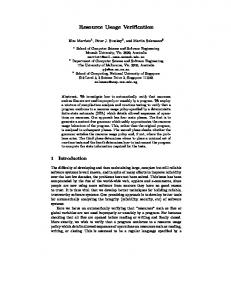
7.2 Objects Identified Using Resource Usage Matrix Figure 5 provides the diagonal sparse matrix after the execution of object identification algorithms on Event Processor Simulator and figure 6 provides its OMT. One can observe that the classes identified have a strong relationship with domain entities. A processor has registers, memory, stack, alu, cache, busses, IOProcessor and synchronisation mechanism, which are obtained by restructuring processes. Some of the identified classes have very little behaviour other than get and set methods. However, the other classes have a very good behaviour indicating a decentralisation of control among newly identified classes. The only way to know how good our heuristics are in identifying good classes can be measured by metric tools. We are currently implementing one such suite of metrics within the RESTRUCT CASE tool. Eventually it would be possible for a programmer to interactively select a few classes and apply design transformations and then measure the quality of the resulting architecture. Future developments of this CASE tool will provide capabilities to perform design transforms based on the help derived from metrics. We observe in this particular case study there are a large group of utility methods which are used from a large number of other methods within the system. These methods have been placed in a library class which is declared as public and static to ensure that they are available to all the class objects which use them.
Submitted to 14th Automatic Software Engineering Conference Length to be reduced to about 9 Pages. printed on 28/07/97 09:31:30
Highways Synctable IOProcessor
Memory
Registers1 Group1
Registers2 Group Figure 5. Diagonal sparse matrix after the execution of object identification algorithm. The columns represent the global variables and the member fields within the user defined types and the rows represent the functions. The coloured areas indicate that the functions modify the corresponding variable. The enclosed areas are the encapsulated classes. 8. Conclusions This paper describes a new algorithm for object identification in legacy procedural software and some important concepts useful for migration from procedural to object oriented software architecture. It introduces a novel approach of viewing a procedural program from an object oriented perspective in which there is single god class which has a large number of global variables & methods, supported by several user defined classes which have no behaviour but data definitions. This view, coupled with repeated restructuring, enables a seamless migration of behaviour from the god class to other classes using design transformation methods. It distinguishes between the processes of translation and transformation and states that these two are orthogonal to each other, thus enabling us to concentrate on design
Submitted to 14th Automatic Software Engineering Conference Length to be reduced to about 9 Pages. printed on 28/07/97 09:31:30
Epsim
Registers
Highways IOProcessor
memparcel
Cache
Memory Stack
Alu
zparcel
stkparcel
SyncTable
procparcel instparcel
hword
fword
dword
qword
Figure 6. Transformed design of Event Processor Simulator transformations to migrate from one design to another, leaving the language issues to be handled by translators. Some basic design transformations which permit partitioning of classes while preserving the system behaviour are described, enabling a series of heuristics to be used in conjunction with design transforms to migrate to a better architecture. It also emphasises on the distinction between design specification of a system and functional specification of a system. Design specification concentrates on the object called design, which defines organisation of components within a system. Functional specification concentrates on what each component is capable of performing and what a combination of components are capable performing together in a given design. In order to improve the structure of legacy software, the design of a program should change while retaining the functional capability, which can be achieved by restructuring. Reverse engineering and subsequent restructuring of software enables migration from poorly structured programs to systems with object oriented topological structure. This kind of migration enables a maintainer of software to obtain the full benefits of a modern methodology, while having a continued availability of software. The object identification algorithms reported in literature do not at the moment produce object oriented design structure. They only identify the candidate objects/classes as receivers. This kind of analysis of existing software will lead to identification of aggregation and association relationships between objects. Procedural languages do not have the facility to express inheritance, hence, where this kind of relationship is needed, the designers using procedural programs would be using aggregation relationships. Hence, it is necessary to analyse all aggregation relationships that occur in procedural programs, with an intention to identifying where these can be converted to inheritances. From this discussion, it is
Submitted to 14th Automatic Software Engineering Conference Length to be reduced to about 9 Pages. printed on 28/07/97 09:31:30
obvious that the software engineer needs assistance from the tool in identifying the OO structure to the system. The tool can provide this advice by performing software metrics on the structures identified in the first phases. It also reports on the results of transformation on a 2500 line procedural program to object oriented structure with the help of the tool described in this paper. The present implementation is supported by an interactive graphical user interface implemented on HP UNIX workstation. The implementation uses INGRES database, 4GL and embedded sql with C programming language. The second version of this system is being developed using Visual J++ on Windows 95 using Microsoft Access database, which implements Unified Modelling Language Interface. 8. References 1.
Chikofsky, E.J., Cross II, J.H., (1990), Reverse engineering and design recovery : A taxonomy", IEEE Software,Vol. 7, No. 1, pp 13-17.
2.
Livadas,P.E.,Roy,P.K.,(1992), Program dependence analysis",IEEE Conference on Software Maintenance.
3.
Sneed, H.M., (1992),Migration of Procedurally Oriented COBOL Programs in an Object-Oriented Architecture, Proc. IEEE
4.
Liu, S.S., Wilde, N., (1990) Identifying Objects in a Conventional Procedural Language : An Example of Data Design
Conference on Software Maintenance., San Deigo, pp 266-271. Recovery", Proc. of the Conference on Software Maintenance. 5.
Booch, G.,(1991), Object-Oriented Design with Applications, The Benjamin/Cummings Publishing Company.
6.
Feijs, L. (1993) Formalisation of Design Methods, Ellis Horwood Series in Computers and their Applications.
7.
Feijs, L. And Jonkers, H.B.M. (1989) METEOR and beyond: industrialising formal methods, In: K.H. Bennet (ED.) Software Engineering Environments: Research and Practice, Ellis Horwood Limited, pp. 255-274..
8.
Bergstra, J.A., Heering, J., Klint,, P (1990) Module Algebra, JACM Vol. 37 No 2 pp. 335-372.
9.
Rumbaugh, J.,Blaha, M., Premerlani, W., Eddy, F., Lorensen, W., (1991)Object-Oriented Modelling and design, Prentice-Hall.
10. UML 11. LOOM 12. Choi, S.C. and Scacchi, W., (1990), Extracting and Restructuring the design of large systems, IEEE Software. 13. Chen, Y.F., Nishimoto, M.Y., Ramamoorthy, C.V.,(1990) The C Information Abstraction System, IEEE Transactions on Software Engineering, Vol. 16, No. 3. 14. Dietrich, S.W., Calliss, F.W.,(1991) The Application of Deductive Databases to Inter-Module Code Analysis", Proceedings of IEEE conference on software maintenance, pp 120-128. 15. Harandi, M.T., Ning, J.Q., (1990), Knowledge Based Program Analysis", IEEE Software. 16. Linton, M.A.,1984, Implementing relational views of programs, Proc. ACM SIGSOFT/SIGPLAN Software Engineering Symposium Practical Software Development Environment, Pittsburgh, pp. 65-72. 17. Pidaparthi, S., (1994) Forward and Reverse Engineering CASE Tool Supporting Multiple Views for Software Development". Internal Report for De Montfort University, Leicester, U.K. 18. Pidaparthi, S., Cysewski, G.,(1996) Migration to Object-Oriented System Structure Using Design Transformation Methods, Proceedings of The Fifth International Conference Information Systems Development - ISD’96.pp 555-571. 19. Pidaparthi, S, Cysewski, G.,(1997) Case Study in Migration to Object-Oriented System Structure Using Design
Transformation Methods, Proceedings of First Euro-Micro Working Conference on Software Maintenance and Reengineering, 17-19,March, 1997. pp 128-135. 20. Zedan, H., Pidaparthi, S., (1997) Formalisation of Design Transformations, Internal Report for DeMontfort University, Leicester, U.K.
Submitted to 14th Automatic Software Engineering Conference Length to be reduced to about 9 Pages. printed on 28/07/97 09:31:30