J. Astron. Space Sci. 26(4), 651–658 (2009)
[Technical paper]
Robustness and Actuator Bandwidth of MRP-Based Sliding Mode Control for Spacecraft Attitude Control Problems Jung-Hoon Keum1† and Sung-Woong Ra2 1
KOMPSAT-5 Program Office, Korea Aerospace Research Institute(KARI), Daejeon 305-600, Korea 2 Division of Electrical Engineering and Information & Communication Engineering, Chungnam National University, Daejeon 305-764, Korea email:
[email protected]
(Received September 17, 2009; Accepted November 20, 2009) Abstract Nonlinear sliding surface design in variable structure systems for spacecraft attitude control problems is studied. A robustness analysis is performed for regular form of system, and calculation of actuator bandwidth is presented by reviewing sliding surface dynamics. To achieve non-singular attitude description and minimal parameterization, spacecraft attitude control problems are considered based on modified Rodrigues parameters (MRP). It is shown that the derived controller ensures the sliding motion in pre-determined region irrespective of unmodeled effects and disturbances. Keywords: variable structure control, sliding surface, nonlinear control, modified Rodrigues parameters
1. Introduction The control of large-angle spacecraft maneuvers generally poses highly nonlinear characteristics, which govern dynamic equations, control rate saturation and its limits, and incomplete state knowledge due to sensor measurement noise or failure. The use of variable structure control for attitude maneuvers has been proposed for the adequate treatment of such problems. An optimal control approach for the sliding surface synthesis problem using quaternions was presented by Vadali (Vadali 1986). Differential geometric approach to single-axis maneuver using Cayley-Rodrigues attitude parameter was formulated by Sira-Ramirez and Dwyer (Dwyer & Ramirez 1988, Ramirez 1988). Nonlinear optimal control theory and feedback linearization methods also have been applied to the spacecraft maneuver problem (Dwyer 1984, Damaren & D’Eleuterio 1989). In this paper, variable structure control for spacecraft attitude maneuvers is considered. The robustness analysis is taken for nonlinear system with parameter variations and disturbances, and the analysis result is applied to regular form of variable structure systems(VSS). Chattering is one of main topics on VSS and a constraint of control signal bandwidth. By studying sliding surface dynamics, calculation of actuator bandwidth is present in the function of control gain factors. To take advantage of the modified Rodrigues parameters: (1) minimal parameterization of attitude representation, (2) singularity avoidance of rotations †
corresponding author
651
652 Keum & Ra a sliding mode controller is derived based on MRP. It is shown that the derived sliding mode controller ensures bound-layer reachability (Dwyer & Ramirez 1988) irrespective of unmodeled effects and disturbances.
2. Theoretical Background In this section, a review of the variable structure control and dynamic equations of motions for a three-axis stabilized spacecraft is presented.
2.1 Equations of Motion The attitude of spacecraft is assumed to be presented by quaternions. The quaternion representation is defined as Φ Φ β0 = cos , βi = ei sin , i = 1, 2, 3 (1) 2 2 where ei is a unit vector corresponding to the axis of rotation and Φ is the angle of rotation. For minimal parameterization of attitude, we use modified Rodrigues parameters(MRP). The transformation from quaternions to the MRP vectorσ is given by (Schaub 1998, Shuster 1993) σi =
βi , i = 1, 2, 3 β0 + 1
(2)
Using Eq. (1), the modified Rodrigues parameters are written as σ = tan
Φ eˆ 4
(3)
Studying Eq. (3) it is evident that the MRP have a geometric singularity at Φ = ±360 degrees. But the non-uniqueness of the MRP allows one to avoid their singularities (Schaub 1998). The MRP kinematic differential equation in vector form by using the spacecraft’s body angular velocity vector(ω), is ¤ 1£ σ˙ = (1 − σ 2 )I + 2[˜ σ ] + 2σσ T ω = B(σ)ω (4) 4 where the notation σ 2 = (σ T σ) is used, and I is the 3×3 identity matrix. The tilde matrix operator [˜ σ ] is defined as 0 −σ3 σ2 0 −σ1 [˜ σ ] = σ3 (5) −σ2 σ1 0 The inverse transformation of B(σ) in Eq. (4) is in explicit vector form (Schaub 1998) B −1 (σ) =
£ ¤ 4 (1 − σ 2 )I − 2[˜ σ ] + σσ T 2 2 (1 + σ )
(6)
Let J be the rigid body inertia matrix and u be control torque vector. Euler’s rotational equations of motions for a rigid body are given by
where
ω˙ = f (ω) + J −1 u
(7)
˜ f (ω) = J −1 [Jω]ω
(8)
MRP-Based Sliding Mode Control 653 2.2 Variable Structure Control The system presented as x˙1 = f1 (x1 , x2 ), x˙2 = f2 (x1 , x2 ) + G(x1 , x2 )u
(9) (10)
is referred to as a regular form in VSC literature, where x1 ∈ Rn , x2 ∈ Rm , u ∈ Rm , and G is m×m matrix. It is possible to specify the sliding manifold s = 0 as (Utkin 1992) s = x2 − s0 (x1 ) = 0
(11)
where s0 (x1 ) is the solution of equation s=0 regarding to x2 . The equation of motion along the manifold s=0 in Eq. (11), or x2 = s0 (x1 ) will be of the form x˙1 = f1 (x1 , s0 (x1 ))
(12)
As a result, we face a design problem for the system with an m–dimensional control s0 (x1 ) rather than (m+n)–dimensional control. Now we consider the disturbance and uncertainty to see the robustness characteristic of VSC. We consider the system with disturbance and uncertainty as the following: x˙ = f + ∆f + (G + ∆G)u(t) + d(t) (13) where x ∈ Rm , and f, ∆f, G, ∆G depend on x and f and ∆f are nonlinear driving term and their uncertainties, G and ∆G are the control gain and its uncertainty, and d(t) and u(t) represent external disturbance and control signals. Futhermore ∆f, ∆G and d are assumed to be bounded by known, continuous functions, i.e. |∆f | 5 F (x, t) |∆G| 5 Γ(x, t) (14) |d| 5 D(x, t) The attractivity of the sliding surface is assured by enforcing the sliding mode existence condition, which for a single input case are given by the following relations: d s0 s−→0− dt lim +
(15)
For general vector–valued situations conditions, Eq. (15) is replaced by the Lyapunov-type condition below: d ds ||s||2 = 2sT 0 and K > 0. P and K assure the two conditions for sliding. P is effective for large s, and K is dominant for small s. Due to uncertainties, Eq. (17) needs to be modified to s˙ = −P s − Ksign(s) + ∆f + d + ∆Gu
(18)
654 Keum & Ra The following selection is sufficient to ensure Eq. (16): K = F + Γ|u| + D >= |∆f + d + ∆Gu|
(19)
From the relation Eq. (19), K is disturbance control factor.
3. Controller Design In this section a sliding mode controller is derived. The measurement of both the spacecraft attitude and angular rate are assumed to be available. The nonlinear model for spacecraft motion can be characterized by Eq. (4) and Eq. (7) and is of regular form as Eq. (9), (10) with x1 = σ, x2 = ω and G = J −1 . The sliding surface is defined as Eq. (11) with s0 (σ) = B −1 (σ)ρ(σ). s
= =
ω − s0 (σ) ω − B −1 (σ)ρ(σ)
(20)
The ρ(σ) determines the desired form of evolution σ, given by ρ(σ) = Π(σ − σd )
(21)
where σd is the desired final value of the attitude parameter, and Π is a diagonal matrix with negative elements. The dynamics for the attitude parameter would be a system with exponential rate of decay. So diagonal elements in Π can be thought of time constant in attitude parameter dynamics. Considering Eq. (16), the sliding mode controller which satisfies the sliding mode existence condition of Eq. (16) is obtained by (Dwyer & Ramirez 1988) ½ ¾ ∂s0 u = −J f (ω) − [B(σ)s0 (σ) + B(σ)s] + P s + Ksat(s, ²) (22) ∂σ The saturation function, sat(s, ²) used to reduce chattering in the control torques, is defined by ½ sign(si ) if |si | > ² sat(si , ²) = i = 1, 2, 3 (23) si if |si | 5 ² ² where ² > 0 is the“boundary layer thickness.”
3.1 Regulation Problem The regulation problem requires that the final attitude of spacecraft be zero, i.e. the desired evolution of attitude parameters σd = 0 in Eq. (21). To simplify the problem, we assume that Π matrix in Eq. (21) is as form of Π = γI with scalar value γ, which yields s0 (σ) to © ª s0 (σ) = 4γ(1 + σ 2 )−2 (1 − σ 2 )I − 2[˜ σ ] + 2σσ T σ (24) which can be further simplified using the [˜ σ ]σ = 0 and the identity [˜ σ ]2 = σσ T − σ 2 I to s0 (σ) = 4γ(1 + σ 2 )−1 σ
(25)
The partial derivative∂s0 /∂σ is given by © ª ∂s0 = 4γ(1 + σ 2 )−1 I − 2(1 + σ 2 )−1 σσ T ∂σ
(26)
MRP-Based Sliding Mode Control 655 3.2 Tracking Problem The tracking problem requires that the attitude of spacecraft follow a desired form of attitude evolution. For tracking, s0 (σ) is derived to s0 (σ)
=
4γ(1 + σ 2 )−1 σ © ª −4γ(1 + σ 2 )−2 (1 − σ 2 )I − 2[˜ σ ] + 2σσ T σd
(27)
The partial derivative ∂s0 /∂σ of Eq. (27) is given by ∂s0 ∂σ
© ª = 4γ(1 + σ 2 )−1 I − 2(1 + σ 2 )−1 σσ T © ª −8γ(1 + σ 2 )−2 σσdT − σd σ T + [σ˜d ] + (σdT σ)I © ª +16γ(1 + σ 2 )−3 (1 − σ 2 )I − 2[˜ σ ] + 2σσ T σd σ T
(28)
3.3 Actuator Bandwidth By replacing sign(s) with sat(s, ²), Eq. (18) becomes x˙ = −P s − K
s + ∆f + ∆Gu + d ²
(29)
when |s| < ², i.e. sliding phase. From Eq. (18), we can see that the sliding mode existence condition is satisfied when |s| = ². It is desirable to keep ² small, so that near ideal sliding mode is obtained. Eq. (29) may be rewritten as s˙ + (P +
K )s = ∆f + ∆Gu + d ²
(30)
which is very similar to a low–pass filter between s and (∆f + ∆Gu + d). If λ ≡ P + K/² is defined. We can find that smaller ² gives larger λ, i.e. higher actuator bandwidth. This gives a lower bound for ² based on actuator limitations. If we set λ = 2ω/3, yielding: ²=
3K 2ω − 3P
(31)
Note that ω in Eq. (31) is the response bandwidth of the actuator. It is very important to note that design parameters P and K assure the sliding condition, and gives actuator bandwidth.
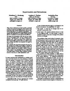
4. Simulation An example of a three–axis rest–to–rest maneuver is presented and the simultaneous reorientation of all axes is considered here, with variable control torques and the following inertia matrix taken from (Dwyer & Ramirez 1988) J = diag[114 86 87] kg − m2 To show the robustness of the controller, disturbance torques are assumed to be d = [0.005 sin(ωt) 0.003 cos(ωt) − 0.005 sin(ωt)]T N − m where ω is the disturbance torque frequency, assumed to be 1 rad/s. And the other initial conditions and design parameters are the following: σ(t0 ) = [−0.1 0.5 1.0]T , ω = [0 0 0]T , K = 0.02I, Q = 0.02I
656 Keum & Ra
Figure 1. Plot of modified Rodrigues parameters trajectories.
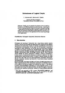
Figure 2. Plot of angular velocity trajectories.
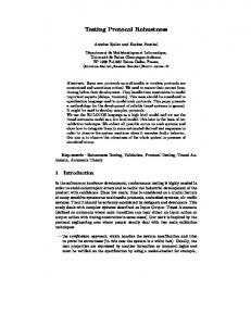
Figure 3. Plot of switching functions.
Figure 4. Switching functions during the terminal maneuver.
The regulation problem is considered. The constant γ = −0.015sec−1 , and the boundary layer thickness is set to ² = 0.001. Also, the control torques are limited to 1.0 N-m. Figure 1 depicts the time trajectories of modified Rodrigues parameters. Figure 2 shows the angular velocity trajectories. Figure 3 and 4 show the switching functions trajectories. Figure 4 shows the switching functions during the terminal maneuver, from the figure one can see that the state trajectories remains well inside switching region specified bound layer thickness. The control torques are applied to accomodate disturbance torques as shown in Figures 5∼7.
5. Conclusions Nonlinear sliding surface design for large-angle spacecraft maneuvers is studied. The sliding
MRP-Based Sliding Mode Control 657
Figure 5. Control Torque u1 .
Figure 6. Control Torque u2 .
Figure 7. Control Torque u3 .
mode controller is derived based on modified Rodrigues parameter, and analysis of robustness is peformed for the derived control scheme in the presence of unmodeled effects and disturbances. The actuator bandwidth is considered using bound layer thickness and sliding mode dynamics. Simulation results show that the control system performs acceptably in the presence of external disturbances.
References Damaren, C. J. & D’Eleuterio, G. M. T. 1989, JGCD, 12, 723 Dwyer, T. A. W. 1984, IEEE Trans. on Automatic Control, AC-29, 769 Dwyer, T. A. W. & Ramirez, H. S. 1988, JGCD, 11, 262 Ramirez, H. S. 1988, IJC, 48, 1359 Schaub, H. 1998, PhD thesis, Texas A&M University Shuster, M. D. 1993, JAS, 42, 439
658 Keum & Ra Utkin, V. I. 1992, Sliding modes in control and optimization (Heidelberg: Springer), p.81 Vadali, S. R. 1986, JGCD, 9, 472