AbstractâWe analyze the decoding algorithm for regular time- invariant LDPC convolutional codes as a 3D signal processing scheme and derive several ...
Towards a GBit/s Programmable Decoder for LDPC Convolutional Codes Emil Mat´usˇ, Marcos B.S. Tavares, Marcel Bimberg, and Gerhard P. Fettweis Vodafone Chair Mobile Communications Systems Technische Universit¨at Dresden, D-01062 Dresden, Germany Emails: {matus, tavares, bimberg, fettweis}@ifn.et.tu-dresden.de
Abstract— We analyze the decoding algorithm for regular timeinvariant LDPC convolutional codes as a 3D signal processing scheme and derive several parallelization concepts, which were used to design a novel low-complexity programmable decoder architecture with throughput in the range of 1 Gbit/s at moderate system clock frequencies. The synthesis results indicate that the decoder requires relatively small areas, even when high levels of parallelism are used.
I. I NTRODUCTION It is well-known that the major challenge when designing highspeed decoders for low-density parity-check (LDPC) codes resides in efficient implementation of the interleaving operations required by the message-passing algorithm. A fundamental measure for the complexity of the interleaving problem presented by an LDPC code is the locality of the connections shown by its underlying Tanner graph. If we number the symbols of a codeword (variable nodes) according to their order of transmission through the channel, the locality of the connections in a graph is expressed by distance between the variable nodes that are checked by a parity-check equation (check node). Another interesting feature of the codes that is desired for efficient decoder implementations is the regularity of their graphs. The regularity can be defined as the invariance of the graph connections through the time. This means that if we observe the connections of a particular variable node (check node) at time instance t, we will find at time instance t + T a similar variable node (check node) with the same connection pattern, where T is the period. If T = 1, we call the LDPC code time-invariant. In general, codes that have regular graphs with local connections are better suited for efficient high-speed implementations. This happens because the complexities associated with the memory architectures and interconnect units are kept low; and because simple parallel architectures based on the independence of the nodes beyond a certain critical distance1 , which is a function of the locality of the connections, can be applied. Furthermore, the graph regularity guarantees very simple memory addressing and also homogeneity in the parallel architecture. In [1], LDPC convolutional codes (LDPCCCs) were presented and later, in [2], they were derived from quasi-cyclic (QC) LDPC block codes. LDPCCCs exhibit the locality and regularity graph properties, which enable very efficient VLSI implementations. Moreover, these codes are not limited to a unique block length because of their convolutional structure (i.e. the same encoder and decoder can be used to encode/decode codewords with different lengths). Encoding can be performed using shift-register operations and, from the theoretic This work was supported by the German ministry of research and education within the project Wireless Gigabit with Advanced Multimedia Support (WIGWAM) under grant 01 BU 370. 1 This will be better explained in the description of LDPC convolutional codes.
point of view, LDPCCCs show better distances properties than their block counterparts. Recently, architecture concepts for closely related quasi-cyclic codes were described [3]. However, these architectures are based on parity check matrices causing design limitations e.g. in parallelization. In [4]–[6], architecture concepts for LDPCCC decoders were presented. These concepts were mainly derived from the pipeline decoding algorithm already proposed in [1]. Such decoders are of low implementation complexity. However, due to their pipeline structure they have high latencies, thus becoming problematic for high-speed applications. In this work, we present the concepts of a novel low-complexity and programmable decoder architecture for time-invariant LDPCCCs that is able to reach throughputs range 1 GBit/s at moderate system clock frequencies. II. LDPC C ONVOLUTIONAL C ODES An (ms , J, K) regular time-invariant LDPC convolutional code is the set of sequences v satisfying vHT = 0, where
HT =
�� �� ��
HT0
···
..
HTms
..
. HT0
..
.
···
.
HTms
..
� �� �� . ��
(1)
.
Here, HT is the diagonal-type semi-infinite syndrome former matrix, i.e., the transposed parity-check matrix. The scalar submatrices HTν , ν = 0, 1, · · · , ms , have dimensions c × (c − b), and so determine the rate of the code, which is given by R = b/c. The parameter ms defines the memory of the convolutional code and consequently the critical distance of the graph. The critical distance of an LDPCCC is given by ms + 1, which means that different graph nodes beyond this distance can be processed independently. The locality of the graph connections is also reflected by the diagonal structure of HT . Moreover, J is the number of ones in each row of HT and K is the number of ones in each column. These last two parameters indicate the density of connections for the graph nodes. From (1), we can also note that the graph representing an LDPCCC must be highly regular. For instance, the scalar matrix HT can be also represented as a polynomial matrix HT (D), like conventional convolutional codes [7]. This matrix has dimensions given by c × (c − b) and its entries are the delay elements Dν , where ν ≤ ms . The encoders for LDPCCCs can be found by performing Gaussian elimination on their polynomial parity-check matrices. The obtained generator matrices for these codes will be also of polynomial nature and can be easily implemented using shift-register operations. The decoding of LDPCCCs can be performed using a modified version of the conventional message-passing algorithm, which is called pipeline-decoder [1]. In the next sections, we will exploit the
Processing window
graph properties of such codes to design efficient architectures for their high-speed decoding.
pt = 2
Processing window
D A
E
d
Pr o flo ces sin w
g
M = K .J M −1
Check node ...
B
...
Variable node Message register
2 1 1
1
...
i
2
I
...
3
C
(a)
t
L K
Check-node
Time slot
Fig. 1. Three-dimensional representation of the decoding algorithm for timeinvariant regular LDPCCCs. The dimensions t, d and i stand for time, depth and iteration, respectively. The code in this picture is a (3, 2, 3) LDPCCC with rate R = 1/3.
(a)
i
..
(b)
L t
t 1
M
Processor M
d
Vector CN operation Vector VN operation
•
(c)
Fig. 2. Graph level parallelization principles: (a) Parallelization in iterationdomain (b) Parallelization in time-domain (c) Parallelization in depth-domain. The inter-processor communication in (a) is unidirectional and in (b) and (c) bidirectional. Combinations of (a), (b) and (c) are possible.
• •
III. A NALYSIS OF PARALLELIZATION C ONCEPTS The parallelization concepts we describe in this section are derived from the graphical representation of the LDPCCCs decoding algorithm. The graph of a regular LDPCCC with rate R = b/c has α · c variable nodes and α · (c − b) check nodes in each time slot (α is a positive integer). Moreover, J is the number of edges leaving each variable node (VN) and K is the number of edges leaving each check node (CN). The total number of variable nodes in such a graph is given by (τe + τt ) · c, where τe and τt are the number of discrete time units in which the encoded and termination sequences have been transmitted, respectively. For instance, we can observe in Fig. 1 the graph of a (3,2,3) LDPCCC with rate R = 1/3. A. 3D Interpretation of the Decoding Algorithm We can describe the decoding algorithm for LDPCCCs as a threedimensional signal processing scheme. The first dimension is time t. The second dimension is what we call the depth d of the graph (i.e., the number of variable nodes in each time slot). Finally, the third dimension is the iteration i. In Fig. 1, we can directly recognize the dimensions t and d. The dimension i is orthogonal to the plane of the paper. From Fig. 1, we can also note that the regularity and locality of the graph connections are evident. In this example, the critical distance is ms + 1 = 4. B. Parallelization Strategies The analysis of the decoding algorithm depicted as a graph is Fig. 1 lead us to conclude that the parallelization strategies listed below in descent hierarchic order can be applied to improve the throughput of the decoder:
Vector operand for CN operation Vector operand for VN operation Message vectors stored in memory
Fig. 3. Principle of node level parallelization of order pt = 2: (a) Messagevectors are loaded from memory, and check and variable node vectoroperations are performed (b) The vector misalignment problem is explained.
Processor 1 ..
Processor I
..
..
Processor 1
I i
Processor 1 ..
..
1
1
Processor L
t
(b) Variable-node
Graph level: the graph is partitioned (segmented) in each of three dimensions as depicted in Fig. 2. In case (a), the individual iterations are mapped on separate processors. This results into the original pipeline decoder architecture [1]. In (b), segments of the graph beyond the critical distance ms + 1 are processed separately. Depth partitioning in (c) distributes sections of the graph along the dimension d over several processors. Due to data dependencies, bidirectional data transfer between processors in (b) and (c) is required, which is in contrast to scenario (a). Node level: this method enables parallel computation of multiple nodes (variable or check nodes) at same time. Operation level: the parallelism within each of the variable and check nodes operations is exploited.
In our current analysis, only the graph level parallelization options (a) and (b) will be further considered. Because of the regularity of LDPCCCs, partial graphs defining the operations of the resulting parallel processors are similar. This indicates that a very homogeneous system can be obtained. In addition to the graph level parallelism, the node level and operation level parallelization concepts are also applied to our work. In particular, our concept for node level parallelization will be better explained as follows because it defines the fundamental computing model we are using. C. Node Level Parallelization Because of the independence and regularity of the graph edges of regular time-invariant LDPCCCs, the SIMD computing model can be used for node level parallelization. In Fig. 3(a), the principle of node level parallelization of order pt = 2 is depicted. Variable-nodes are grouped into non-overlapped segments called processing windows of length pt . The message-vectors of length pt are loaded sequentially and fed to the vector computing elements responsible for processing pt check or variable operations. A drawback of this simple computing model is the occurrence of memory misalignments for one of the processing modes (i.e., variable or check node processing). This happens because the messagevectors for check and variable nodes do not match. This situation is demonstrated in Fig. 3(b). The dashed rectangles represent the message-vectors as they are stored in memory. Note that, in this case, the message-vectors are already aligned for variable node computations, e.g., vectors D and E. Unfortunately, the same does not have to be true for the check node operations, e.g., vectors B and
Shuffle network
Vector-memory load
Inverse shuffle network
CN-Unit
FIFO
B
B’
(K,J)=(7,3)
CN computation Results Vector-memory store
LD vector 1
J+1
Node 0
(K,J)=(15,3) 800
Fclk=250MHz 600
400
J 3
CN-opr
0 0
50
100
pt
150
200
250
Node J-1 ST vector
LD - Load vector from memory ST - Store vector to memory CN opr - Check-node operation VN opr - Variable-node operation
Assume that processing flow as in Fig. 5 and one cycle per each operation, the achieved decoder throughput T per clock cycle and iteration is given by
Node J (Channel value)
VN opr Node 0
ST vector
Shuffle cycles
200
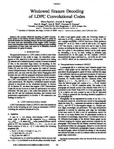
Fig. 6. Dependence of the throughput of a LDPCCC parallel decoder architecture on the degree of parallelism pt for one iteration and single-port RAM scenario. In the case of dual-port RAM, the speedup factor ≈ 1.7 is achieved. The projected processor clock frequency was 250 MHz.
LD vector
...
Node K-1
LD vector 2
LD vector
1
2K
...
Shuffle
(2 cycles)
...
Node 0
LD vector 2
(K,J)=(8,3)
1000
Fig. 4. Principle of parallel check node computation for parallelism pt = 2. The shuffle network is dedicated to correction of vector operand misalignments in memory (Fig. 3). In order to preserve memory consistency, the inverse shuffle is applied prior to saving the results into memory. LD vector 1
(K,J)=(5,3)
1200
Rearanged vector
B’
Throughput [Mbits/s].
B
(b)
-1
Shuffle
ST vector 1 2K cycles
ST vector 2
...
Node 0
Node K-1
Shuffle-1 ST vector 1 ST vector 2
(a)
Fig. 5. Processing flow during one check and variable node operations for the proposed processor architecture. Note that for dual-port memory the load and store phases of consecutive procedures my overlap. This results in speedup factor of ≈ 1.7 over the single-port memory scenario.
C. Hence, a vector realignment procedure is necessary prior to check node computations. An example of check node computation with vector realignment is shown in Fig. 4. Firstly, a pair of message-vectors is loaded from vector-memory. After this, the vector B is created by proper shuffling of two message-vectors, which then is used for check node computation. In addition to vector B, also a complement vector B’ is produced. This vector B’ enables the inverse shuffling that is required before the memory store operation. We can observe from Fig. 3(b) and Fig. 4 that the permutations to be used in the shuffling operation correspond to cyclic rotations. In general, in order to support any LDPCCC decoder with pt > 1, the total number of rotations to be implemented in the shuffle-network is pt + 1. However, if we restrict ourselves to a particular LDPCCC, the exact number and type of rotations necessary for implementation of the shuffle-network are related to polynomial form of the paritycheck matrix H(D). In this case, code-specific complete set of cyclic rotations is given by the elements of matrix S = log D [H(D)]
mod (pt ),
(2)
where log(.) and mod (.) operations are performed element-wise on matrix H(D). D. Decoder Performance Figures In order to assess the performance figures of proposed LDPCCC decoder, we present in Fig. 5 the procedures for the execution of single check and variable node computations. The decoding algorithm requires that in a first half-iteration the check-node updates are computed (Fig. 5(a)), followed by the variable-node updates (Fig. 5(b)) in the second half iteration. Note that the double read (store) from (to) memory in the check node procedure can be eliminated if we use an architecture with two memory banks.
T =
(K − J) · pt tCN · J + tV N · K
Bits Cycle × Iteration
�
(3)
where tCN = 4K + 3 and tV N = 2J + 2 are cycle counts for single check and variable node operation, respectively. As expected, the throughput in (3) is linear with pt . It is worth to mention that further minimization of the denominator in (3) is possible by applying pipelining in the decoding flow of Fig. 5. This is possible because the load and store operations are independent to each other and the consecutive store-load phases may overlap. In this case, execution time of check and variable-node operations reduces approximately to tCN = 2K + 3 and tV N = J + 2, respectively. This results in a speedup factor of ≈ 1.7, depending on the LDPCCC used. Note that two-port memory must be used in this case. The dependence of the decoder throughput on the parallelism pt of some selected LDPCCCs is presented in the Fig. 6. In order to achieve the throughput of 1 GBit/s at 250 MHz clock frequency, the parallelism 100 ≤ pt ≤ 220 is necessary. Note that we define the throughputs in Fig. 6 as being related to one single iteration. The latency of the proposed decoder architecture depends on the codeword length L to be processed, parallelism pt , number of iterations I and is given by
�
D=I·
�
L ms + K · pt pt
��
· (tCN · J + tV N · K)
[Cycles] , (4)
where the term L/(K · pt ) represents the number of processing windows per code length L and ceil function �·� is overhead caused by LDPCCC termination. Finally, the processor minimum memory requirements can be expressed by
�
C=
�
L ms +2· K pt
�
�
· pt
· K · (J + 1) · N
[Bits] ,
(5)
where L/K is the number of time slots in the graph, the overhead component 2.�ms /pt �pt is due to LDPCCC termination and N stands for bit-width used for the representation of soft-bits. Assuming L/K >> ms , equations (4) and (5) then reduce to D ≈ (I/pt ) · (L/K) · (tCN · J + tV N · K) C ≈ L · K · (J + 1) · N
[Cycles]
(6)
[Bits] .
(7)
In
DMA
Out pt . N
pt . N Scalar Mem
p t .N
pt . N
Code-specific Shuffle Technology: - UMC 130nm - 8 metal layers Timing constraints: - 250MHz worse case Area utilisation: - 78-84%
1.2
pt . N
1
pt . N
0.8
Shuffle
CALU 1
...
p t .N
pt . N
pt . N CALU pt
FIFO
pt . N PCU
Full Shuffle
1.4
AGU
Inst Mem
1.8 1.6
Vector Memory
pt . N
VALU 1
...
VALU pt
p t .N
Shuffle-1
0.6
3.8x
0.4
2.4x
0.2 0 0
20
40
60
pt
80
100
120
140
pt .N
Fig. 7.
Block diagram of the proposed parallel LDPCCC processor.
IV. P ROCESSOR A RCHITECTURE AND I MPLEMENTATION D ETAILS Based on the concepts presented above, a novel processor architecture has been developed. This architecture serves as a basic block for building multi-processor solutions that exploit the graph level parallelisms from Fig. 2(a)-(b). The block diagram of the processor is shown in Fig. 7. The data-path of processor (i.e., local vector memory), shufflenetworks, check node (CALU) and variable node (VALU) functional units, follows the concept of parallel computing presented in section III-C. In addition to this, a relatively powerful address generation unit (AGU) was implemented. This AGU supports register-based basisoffset-displacement modulo addressing modes, which enables effective access of vector operands in the vector memory. Fully support for pipelining of the procedures in Fig. 5 (considering that two-port RAMs are used) is guaranteed by generation of two addresses in parallel. In order to improve even more performance, instruction level parallelism was exploited based on the VLIW concept, additionally to data level parallelism (SIMD). Furthermore, the multi-processor configurations implementing the graph level parallelisms from section III-B are supported by FIFO-based direct interfaces (In/Out) to data path, as well as, by a DMA interface to vector memory. In order to estimate implementation costs, hardware model was synthesized using the SYNOPSYS tool flow and UMC-130nm 8metal layers technology. In addition to this, some critical components, e.g., shuffle-networks were place-&-routed. The area estimation of the crucial processor components is summarized in Table I. The area estimation of a full-interconnect parallel shuffle-network (all cyclic rotations supported) in dependence on parallelism is depicted in Fig. 8. As expected the area grows quadratically with parallelism. This is in contrast to code specific shuffle-network. In this example, the code specific shuffle-network has been designed to support (127,3,5) LDPCCCs from [2]. It is worth to mention that, if no full flexibility is required, than the shuffle-area can be considerably reduced by a codespecific design. This is particularly important for higher parallelism levels, i.e., pt > 32. V. C ONCLUSION The ideas for design of high-throughput programmable decoder architectures for regular time-invariant LDPC convolutional codes have been considered. Firstly, the concepts for parallelization on graph, node and operation levels have been presented. Based on this, a generic parallel processor architecture has been developed. This processor constitutes the main building block of multi-processor schemes that exploit all the parallelism options presented in this
Fig. 8. Dependence of the area of the shuffle-network after place-&-route for parallelism pt . The areas of the full-interconnect shuffle-network and codespecific network are compared. The code-specific network was designed to support five selected LDPCCCs from [2]. TABLE I E STIMATED A REA OF C RUCIAL P ROCESSOR C OMPONENTS IN mm2 FOR B IT-W IDTH N = 8. pt = 64
pt = 32 0.20
Full shuffle: 2×
1.00
CALU: 16 operands
1.73
0.87
VALU: 8 operands
1.11
0.56
Vector Mem. 32 kB*
2.27
ROMs in AGU: 1 kB Instruction Mem: 256 × 32 Byte
�
0.95 0.04 0.38
6.53 mm2
2.99 mm2
*This memory is oversized. For practical realizations please consider (5).
paper. The performance analysis, implementation details and results have demonstrated the feasibility of that methodology for the design of programmable, high-throughput decoders. Currently, the authors are working towards a silicon prototype. In future work, other node level concepts of parallelization will be exploited. For instance, MIMD computation models will be investigated. R EFERENCES [1] A. Jim´enez Feltstr¨om and K. Sh. Zigangirov, “Periodic time-varying convolutional codes with low-density parity-check matrices,” IEEE Trans. Inform. Theory, vol. 45, no. 5, pp. 2181–2190, Sept. 1999. [2] R. M. Tanner, D. Sridhara, A. Sridharan, T. E. Fuja, and D. J. Costello, Jr., “LDPC block and convolutional codes based on circulant matrices,” IEEE Trans. Inform. Theory, vol. 50, no. 12, pp. 2966–2984, Dec. 2004. [3] T. Richardson and V. Novichkov, “Methods and apparatus for decoding LDPC codes,” in U.S. Patent No. 7,133,853, 2006. [4] S. Bates and G. Block, “A memory-based architecture for FPGA implementations of low-density parity-check convolutional codes,” in Proc. IEEE International Symposium on Circuits and Systems (ISCAS), Kobe, Japan, 2005. [5] R. Swamy, S. Bates, and T. Brandon, “Architectures for ASIC implementations of low-density parity-check convolutional encoders and decoders,” in Proc. IEEE International Symposium on Circuits and Systems (ISCAS), Kobe, Japan, 2005. [6] S. Bates, L. Gunthorpe, A. E. Pusane, Z. Chen, K. Sh. Zigangirov, and D. J. Costello, Jr., “Decoders for low-density parity-check convolutional codes with large memory,” in Proc. NASA VLSI Symposium, 2005. [7] Shu Lin and D. J. Costello, Jr., Error control coding, Pearson Prentice Hall, Upper Saddle River, NJ, 2nd edition, 2004.