[4] Simon Gibbs, Constas Arapis, Christian Breiteneder, "Virtual Studios: The State of the Art,". Eurographics'96 ... and Technology. Web: http://vdream.kist.re.kr.
2000
THE INTERNATIONAL JOURNAL OF VIRTUAL REALITY
1
SCENE GRAPH FOR DYNAMIC VIRTUAL ENVIRONMENT: SPANGRAPH Hyun Suk Kim, Heedong Ko, Kunwoo Lee Seoul National University, KOREA Lae Hyun Kim, Jaehong Ahn, Kyoung Dong Park Korea Institute of Science and Technology
ABSTRACT The VRML (Virtual Reality Modeling Language) file format is a popular file format for describing a graphical scene: object shapes, appearance properties, animation, and interactions. However, the format does not provide any mechanism for describing the order of objects’ appearances or their changes over time. Instead, an interface to Java is offered for controlling the temporal relationships between objects in the scene. The use of Java makes it difficult for a person with his programming skill to author a dynamic virtual environment. In this paper we attach a span and an age to each object and their hierarchical and temporal relations are expressed in a new data structure, called a span graph (SpanGraph). An object in the span graph, when alive, grows its age and performs associated actions according to its age during the extent of the time span. Furthermore, the object may have child objects whose spans are sub-extents of the parent span. In this paper, we demonstrate uses of the SpanGraph in virtual studio and virtual engineering design applications.
1. Introduction In order to describe a scene in a virtual environment (VE), we need linguistic construct to describe the objects’ appearances as well as their movements and interactions. VRML (Virtual Reality Modeling Language) [1] provides a object-oriented hierarchical construct to describe the object’s appearance, its animation, and basic interaction with the user. In addition, VRML provides additional construct to describe horizontal control between objects in the hierarchy, called ROUTE. For example, in case of Transform in Figure 1, a coordinate system of an object may be transformed according to upper level in the hierarchy in the vertical direction. If the object is connected to other objects in the hierarchy through ROUTE (horizontal dotted lines), the routed objects may change the coordinate system as well. Hence, the user can express the interdependent relations between objects in the hierarchy both vertically through the hierarchy and horizontally through ROUTE.
2000
THE INTERNATIONAL JOURNAL OF VIRTUAL REALITY
2
However, this attribute control mechanism in VRML falls short in describing the order of attribute control relations. Furthermore, it is very cumbersome to make an object appear or disappear from the scene. Recently, VRML EAI (External Authoring Interface) and JavaScript support [2] are used to overcome this shortcoming. However, these extensions are procedural and hard to author and change by non-programmers. Transform
Transform
Transform
Timer
Interpolator
Horizontal Relation Box
Sphere
Vertical Relation
Figure 1: Attribute control diagram In this paper, we introduce an extension of a VRML hierarchy, called SpanGraph. In SpanGraph, we assign a span and an age to all objects in the hierarchy. With the extension, it is possible to describe the ordering information between the attribute controls and temporal relations in the hierarchy without programming. For example, the attribute values of the object like its shape, appearance, and position may change over the span of the object’s life. A controlling object may issue appearance, growth, or disappearance acting messages to its child objects according to the time line. Because the controlling object also has its own span and age, it is managed by another control object, forming a control hierarchy. In the next section we compare the descriptive efficiency of VRML and SpanGraph in expressing the control order information. Then the age-span structure and its control object in our implementation will be introduced with a detail example. In order to demonstrate the functional completeness and generality of SpanGraph, we have introduced two application examples: one in virtual studio for the production of live presentation graphics and the other in virtual prototyping for animating the joint movements among components of an assembly.
2. SpanGraph Figure 2 is an example of control order of objects that are both hierarchically related and temporally related. The horizontal axis represents progression of time while the vertical axis enumerates the objects in the scene. Object 4 contains object 1, 2, and 3, and they are temporally related: Object 1 precedes 2, and object 2 starts object 3. Object 4 and 7 are related on the time axis but the subobjects of object 7, objects 5 and 6, are independent from sub-objects of object 4. Furthermore, these objects must appear and disappear from the scene depending on their time span and the location on the time axis.
2000
THE INTERNATIONAL JOURNAL OF VIRTUAL REALITY
Object 1
3
Object 4
Object 2 Object 3 Object 5
Obejct 7 Object 6
Object 8
Object 11 Object 9 Object 10
Figure 2: An example of information presentation order Such dynamic ordering and temporal relation are very difficult to express in a static scene graph oriented format like VRML. Figure 3 shows how the presentation order of Figure 2 can be expressed using VRML, EAI, and Java Script extensions to VRML. Here TimeSensor for the entire scene activates a Java EAI script that activates object 4 TimeSensor, object 7 TimeSensor, and object 11 TimeSensor. These three TimeSensors activates their associated Java Scripts to send add_children messages: objects 8, 9, 10 by object 11 TimeSensor; objects 5, 6 by object 7 TimeSensor; and objects 1, 2, 3 by object 4 TimeSensor. Note that it is possible to represent all the time relations using only one global TimeSensor but it would be difficult to modify when the global time changes. In the SpanGraph, each object has its own time line and the object may change over time. Figure 4 is a SpanGraph representation of the example in Figure 2. In the Span-Graph, each object 4, 7, 11 has its own time line between object 4 and 1, 2, 3 are transparent from the structure. Hence it would be easier for the author to make changes to the control order than use VRML with EAI and Java script extensions.
2000
4
THE INTERNATIONAL JOURNAL OF VIRTUAL REALITY
Object 1 Object 2 Object 3 Object 5 Object 6 Object 8 SceneGraph Object 9 Object 10 Object 4 TimeSensor
Java EAI Script
Object 7 TimeSensor
Java EAI Script
Object 11 TimeSensor
TimeSensor
Java EAI Script
Java EAI Script
Figure 3: Ordering control in VRML Object 1 Object 4 vdTimeline
Object 2 Object 3
SpanGraph
Object 7 vdTimeline
Object 5 Object 6 Object 8
Object 11 vdTimeline
Object 9 Object 10
Figure 4. An Example of SpanGraph
2000
THE INTERNATIONAL JOURNAL OF VIRTUAL REALITY
5
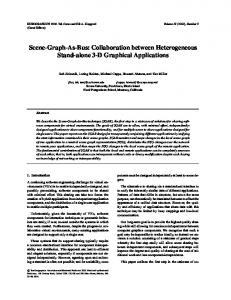
Each object has its own Timeline and the child objects are ordered in its parent object’s Timeline. When an object is aged in its own time line and may issue appear or disappear messages to the child objects. Figure 5 gives various time setting examples. For brevity, we assume each object is child of the previous object: Object 2 is respect to Object 1, Object 3 is respect to Object 2 and so on. Object 1 starts at time 0, Object 4 starts after 15 units of time from the time Object 3 starts. Object 6 starts when 50% of the entire elapsed time of Object 5 has passed. Object 8 starts at 100 in the global time scale. As you can see, one can specify various temporal settings and relations easily and intuitively in SpanGraph than in VRML. 10
20
30
40
50
60 70
80
90 100 110 120 130 140 150 160
Object 1 (Span 40, Global 0) Object 2 (Span 40, Global 30) Object 3 (Span 30, Age 20) Object 4 (Span 50, Age 15) Object 5 (Span 40, Percent 0) Object 6 (Span 20, Percent 50) Object 7 (Span 30, Percent 100) Object 8 (Span 70, Global 100)
Figure 5: An Example of Various Time Setting Method in Timeline Object Now we shall compare the Timeline feature with that of VRML. There are two cases with Timeline: one is setting time relative to the age of the base object, the other is setting time relative to the global time axis. We shall exclude the former case because Java is necessary to implement it with VRML. The latter case can be made by VRML, and example code is as follows: TimeSensor { startTime 0.0 stopTime Span } DEF T1 Transform { … } DEF P1 PositionInterpolator { key [ 0.0 … 0.5 ] keyValue [ 1 1 1, … ,5 5 5 ] } DEF T2 Transform { … } DEF P2 PositionInterpolator { key [ 0.2 … 0.6 ] keyValue keyValue [ 1 1 1, … ,5 5 5 ] } DEF P3 OrientationInterpolator { Key [ 0.5 … 0.9 ] KeyValue [1 0 0 0, … ,1 0 0 1.57 ] } ROUTE TimeSensor.fraction_changed TO P1.set_fraction ROUTE TimeSensor.fraction_changed TO P2.set_fraction ROUTE TimeSensor.fraction_changed TO P3.set_fraction
2000
THE INTERNATIONAL JOURNAL OF VIRTUAL REALITY
6
ROUTE P1.value_changed TO T1.set_scale ROUTE P2.value_changed TO T2.set_translation ROUTE P3.value_changed TO T2.set_rotation This is an example that P1, P2 and P3 begin to interpolate when their ages reach 0.0, 0.2 and 0.5, respectively, in the global time axis. The next sample script shows the same example expressed using SpanGraph. Here Timeline has its own time axis setting the activation time of the child objects. The example shows that it is more convenient to activate objects using Timeline. In the case of VRML, Java is essential to make object appear or disappear. If Java is not used, animation starts by showing both T1 and T2 objects. In contrast, Timeline gives an 'appear' message to T2 after P1 stops growing, thereby activating P2 and P3. Clearly the scene can be controlled so that objects may appear at the necessary time. In the next section we shall describe a detailed description of our SpanGraph implementation and its operation. vdTimeline { Offsets [ "Global 0", "Global 0", "Global 0", "Global 0.2", "Global 0.5" ] Objects [ T1, P1, T2, P2, P3 ] } vdLinker P1.value TO T1.scale vdLinker P2.value TO T2.translation vdLinker P3.value TO T2.rotation
3. Age-Span Structure In this paper Growable class is provided to assign a span and an age to an object. It means that the object can grow during its span. The object has three message interfaces for maintaining its growth. The first is to appear. When this message is received, the object appears in the computer screen. The second message is to grow. When an object receives a grow message, the object changes its shape, position, or appearance with an aging process. The last message is to hide. The hide message hides the object from the computer screen. These messages must be called sequentially and are called by the upper level control object, i.e. vdTimeline, according to the time. That is, a control object sends an appear message at the appear time of a child object. Then it sends a grow message continuously until the age of the child object reaches its span. Finally, it sends a hide message for removing the object from the screen. An age span object, "Rotation Animator", is shown in the following example. The attributes are composed of the identity, span, rotation axis, rotation center, start angle of rotation, and stop angle of rotation of the object to rotate. If this object receives the appear message, it takes the rotation transform
2000
THE INTERNATIONAL JOURNAL OF VIRTUAL REALITY
7
matrix related with the start angle and applies it to the child object. Then the appear message it received is propagated to the child object. When receiving a grow message, this object changes its age and makes the proper rotation at the current age between the start angle and the stop angle. The grow message is propagated to a child object. The grow message is ignored after the age reaches its span. Lastly, this object receives the hide message, it propagates it to the child object for disappearance.
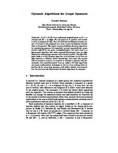
vdRotationAnimator { vdStringParam Name; vdFloatParamSpan; vdVectorParam Pivot; In VRML, authoring the vdRotationAnimator shown in the above example is more complex where several objects are made and connected through ROUTE as shown in next VRML script. The detail explanation about VRML script is omitted. Transform { children USE Child; } OrientationInterpolator { fraction 0.2 key [ 0.0 …. Span ] keyValue [ StartAngle … FinalAngle ] } TimeSensor { startTime 0.0 stopTime Span } ROUTE TimeSensor.fraction_changed TO OrientationInterpolator.set_fraction ROUTE OrientationInterpolator.value_changed TO Transform.set_scale Now an example of SpanGraph is introduced. This example performs the following sequence: firstly, if a user input is originated, four screens are gathered in some position to become one large screen. Then if another input is originated, one large screen moves out of the screen and is scaled to a dot simultaneously. For making such presentation, the objects must appear and grow in sequence as shown in Figure 6. Figure 7 shows the object hierarchy for it. In this hierarchy, the root node is vdQueueSheet. It is always the root node of SpanGraph in our implementation. The following script describes the SpanGraph for this example.
2000
THE INTERNATIONAL JOURNAL OF VIRTUAL REALITY
vdQueueSheet { Name "RoundScreen ( S3, S2 ) " Object DEF seq vdTimeLine { Objects [ DEF button1 vdButtonSensor { Label "ScreenIn" Object NULL }, DEF screenPos vdPositioner { Translation 0 0 -1000 Object DEF screens vdContainer { Objects [ DEF srnTop vd3DModel {...}, DEF srnBottom vd3DModel {...}, DEF srnFront vd3DModel {...}, DEF srnBack vd3DModel {...} ] } }, DEF button1Container vdContainer { Objects [ DEF rotor1 vdVectorInterpolator { Span 160 Frames [ 0, 160 ] Values [ 0 0 180, 0 0 720] }, DEF trans1 vdVectorInterpolator { Span 160 Frames [ 0, 1, 160 ] Values [ 0 0 -1000, 0 600 0, 0 400 0 ]}, DEF scale1 vdVectorInterpolator { Span 160 Frames [ 0, 80, 160 ] Values [ 0.1 0.1 0, 0.5 0.5 0.2, 2 2 2 ] } ] }, DEF button2 vdButtonSensor { Label "ScreenOut" Object DEF button2Container vdSequencer { Objects [ DEF scale2 vdVectorInterpolator { Span 20 Frames [ 0, 10, 20 ] Values [ 2 2 2, 0.5 0.5 0.2,0.1 0.1 0.1 ]}, DEF moveOut vdVectorInterpolator { Span 60 Method cubic Frames [ 0, 12, 24, 36, 48, 60 ] Value 0 0 -100 Values [0 400 0,100 200 80,60 -200 100, -60 -200 100,-120 0 110, -500 800 1000 ] } ] } } ] Offsets [ "Global 0", "Percent 100","Percent 0", "Percent 100" ] } } vdLinker { SourceObject USE rotor1 SourceParam "Value"
8
2000
THE INTERNATIONAL JOURNAL OF VIRTUAL REALITY
TargetObject USE screenPos TargetParam "Rotation" } vdLinker { SourceObject USE trans1 SourceParam "Value" TargetObject USE screenPos TargetParam "Translation" } vdLinker { SourceObject USE scale1 SourceParam "Value" TargetObject USE screenPos TargetParam "Scale" } vdLinker { SourceObject USE scale2 SourceParam "Value" TargetObject USE screenPos TargetParam "Scale" } vdLinker { SourceObject USE transp1 SourceParam "Value" TargetObject USE mat2 TargetParam "Transparency" } vdLinker { SourceObject USE moveOut SourceParam "Value" TargetObject USE screenPos TargetParam "Translation"}
10
20
30
40
50
60 70
80
90
100 110 120 130 140 150 160
button1 screenPos srnTop srnBottom srnFront srnBack button1Container rotor1 trans1 scale1 button2 button2Container scale2 moveOut
button1 is activated.
button2 is activated.
Figure 6. Execution of vdQueueSheet Object “RoundScreen” on Time Axis”
9
2000
THE INTERNATIONAL JOURNAL OF VIRTUAL REALITY
10
Figure 7. Structure of vdQueueSheet Object “RoundScreen First, The entire object execution is blocked by the “button1” vdButtonSensor object because “Percent 100” in vdTimeLine “seq” means “when the previous object is dead”. When a user activates the button, the vdTimeLine “seq” processes the next object, vdPositioner “screenPos”, and its child object “screens”, which contains the four screen model. At this moment, vdContainer “button1Container” object is executed simultaneously because, “Percent 0” in “seq” means “when the previous object is created”. And the values in child object vdInterpolator of “button1Container” is propagated to “screenPos” object via vdLinker. Then the four screen objects “screens” are animated. When the object “button1Container” is dead, the next object “button2” in “seq” is executed. Because the object “moveOut” is blocked by the object vdSensor “button2”, an activation is required for executing the “moveOut”, which has vdInterpolator whose values will be propagated to the object “screenPos” for moving out the four screen objects “screens”.
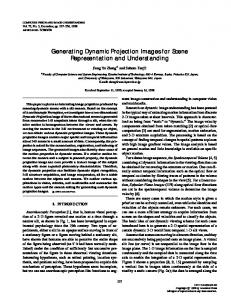
4. Applications Age-span structured object and its SpanGraph have been implemented on a Silicon Graphics Inc. IRIS Performer [3] where it is being used for development of Virtual Studio [4] VDreamSet. VDreamSet, facilitates video texture mapping with an SGI DIVO [5], alpha plane management for virtual blue screen, and camera control for linking with an Ultimatte Memory Head [6, 7]. VDreamSet was used by the Munhwa Broadcasting Company, Korea, in broadcasting the ballot count in the election of the members of the National Assembly in 1996 and in the election of the President in 1997. Figure 8 shows two screen shots during the broadcasts. In this application, the SpanGraph was used for opening and closing the elevator doors and inserting the voting papers to a ballot box.
2000
THE INTERNATIONAL JOURNAL OF VIRTUAL REALITY
Figure 8. Screen Shot of Virtual Studio VdreamSet
11
2000
THE INTERNATIONAL JOURNAL OF VIRTUAL REALITY
12
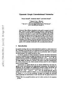
Figure 9. Virtual Prototyping Example As another application, it is used in virtual prototyping software as shown in Figure 9. It is primarily used in virtual prototyping for post processing of analysis result. A SpanGraph is used for assembly and disassembly simulation of parts. In addition, the efficient authoring software shown Figure 10 was developed.
Figure 10. SpanGraph authoring environment
2000
THE INTERNATIONAL JOURNAL OF VIRTUAL REALITY
13
5. Conclusion Timeline feature provides the benefit that user can control the sequence of showing necessary information without other program's support. And parent object of the Timeline can also control the times of children, because its children are modulated. It is the benefit of objects, which have hierarchical structure, including Timeline that they can express modulated information This hierarchical structure enables to make SpanGraph.
REFERENCES [1] VRML, http://www.vrml.org [2] Java, http://www.java.org/ [3] Performer, http://www.sgi.com/developers/technology/graphics/performer.html [4] Simon Gibbs, Constas Arapis, Christian Breiteneder, "Virtual Studios: The State of the Art," Eurographics'96 State of the Art Reports [5] DIVO, http://www.sgi.com/developers/marketing/ forums/divo_gvo/index_no_download.html [6] Ultimatte Corporation, http://www.ultimatte.com [7] Ultimatte Memory Head, Operations Manual, Ultimatte Corp., 1993
Author contact information: Hyun Suk Kim, Heedong Ko, Kunwoo Lee Mechanical Design and Production Engineering Seoul National University Seoul, KOREA Lae Hyun Kim, Jaehong Ahn, Kyoung Dong Park Korea Institute of Science and Technology Web: http://vdream.kist.re.kr