FULL PAPER International Journal of Recent Trends in Engineering, Vol 2, No. 5, November 2009
Sensorless Control of Induction Motor with Extended Kalman Filter on TMS320F2812 Processor R. Gunabalan1, V. Subbiah2 and B. Rami Reddy3 1
Sri Ramakrishna Engineering College/EEE (PG), Coimbatore-641 022, TamilNadu, India Email:
[email protected] 2 Sri Krishna College of Engineering and Technology/EEE, Coimbatore-641 009, TamilNadu, India Email:
[email protected] 3 Pondicherry Engineering College/EEE, Puducherry, India Email:
[email protected]
Abstract–This paper describes discretized Extended Kalman Filter (EKF) for speed estimation of squirrel cage induction motor. Speed and rotor fluxes are estimated from the measured terminal voltages and currents without anymore additional filter. There is a mathematical basis that yields excellent simulation and real time results. In this, speed is considered as a parameter and state. The speed of an induction motor is estimated by MATLAB simulation under low speed regions and it is verified using TMS320F2812 DSP Code Composer Studio. Estimated values along with other measured states are used for closed loop control. The current control is performed under synchronously rotating reference frame and the estimated speed information is used for the reference frame transformation of the current controller. At low speeds, where noise is predominant, performance is improved due to the filtering action of the EKF.
system configuration is discussed in section IV. Simulation and CCS results are discussed in section V. II. EKF ALGORITHM The main design steps for a speed sensorless induction motor drive implementation using the discretized EKF algorithm are as follows: A. Selection of the time domain induction machine model. B. Discretization of the machine model. C. Determination of the noise and state covariance matrices Q, R and P. D. Implementation of the discretized EKF algorithm. E. Tuning of the covariance matrices.
Index Terms– Extended Kalman Filter, Sensorless control
A. Time Domain Induction Machine Model To estimation the rotor speed of an induction machine using EKF, various machine models have been used. Generally the model is expressed in stator flux oriented reference frame. In EKF, the rotor speed is considered as a state variable and parameter. This makes the system matrix A nonlinear i.e. A = A ( X ) . The state space representation of the system is as follows:
I. INTRODUCTION Sensorless vector control of an induction motor drive essentially refers to vector control without any speed sensor. Speed sensor is not suitable for the environmental conditions, which suffers due to large shocks. Sensorless vector control is suitable from the point of reliability of the equipment, cost effectiveness and less maintenance. The speed is estimated from the measured terminal voltages and currents. Full order observers in [5] – [7] estimate all the state variables and are sensitive to any noise in the measurements of currents, voltages and speed. They require filters to remove the noise signals.
dX = AX + BU dt Y = CX
i qss
[
i qss
Y = i dss
EKF is employed to estimate the motor state variables by only using the measurements of stator voltages and currents [1], [3]. During the estimation procedure, these signals are not filtered. The accuracy of the speed estimation depends on the motor parameter variations and the accuracy of measured voltages and currents. The EKF is a recursive optimum stochastic state estimator which can be used for the joint state and parameter estimation of a non-linear dynamic system in real time by using noisy monitored signals that are disturbed by random noise. The main contributions of this paper are organized as follows. Section II reviews the EKF algorithm and implementation is given in section III. Induction motor drive
[
U = v dss
14 © 2009 ACADEMY PUBLISHER
[
X = i dss
φ drs
]
T
v qss
= is
]
T
φ qrs
(1) (2)
ωr]
T
FULL PAPER International Journal of Recent Trends in Engineering, Vol 2, No. 5, November 2009 ⎡−1 ⎢T * ⎢ s ⎢ 0 ⎢ A = ⎢ Lm ⎢ ⎢τr ⎢ ⎢ 0 ⎢ ⎣⎢ 0
' s
−1 T s* 0 Lm
L Lr Lm L 's L r τ r −ωr −1
ωr
0
⎤ 0⎥ ⎥ 0⎥ ⎥ ⎥ 0⎥ ⎥ ⎥ 0⎥ ⎥ 0 ⎦⎥
' s
τr
τr
τr
0
0
⎤ ⎥ ⎡1 ⎥ 1 ⎥ C =⎢ ⎣0 σLs ⎥ ⎥ 0 ⎥ 0 ⎥ 0 ⎥⎦
⎡ 1 ⎢σL s ⎢ ⎢ 0 B = ⎢ ⎢ 0 ⎢ ⎢ 0 ⎢ 0 ⎣
ω r Lm
Lm L L rτ r − ω r Lm L 's L r −1
0
0
0 1
0 0
Bd
where, R 1 = T s*
s
+ R
(L L 's
r
m
/ Lr )
2
r
τ r -rotor time constant= L r
Rr
ω r -motor angular velocity (rad/s) B. Discretized Induction Machine Model For digital implementation of the EKF, the discretized machine equations are required. These can be obtained from (1) and (2). X (k + 1 ) = A d X ( k ) + B d U ( k )
Y ( k ) = CX ( k )
Ad
(3)
A d ≈ I + AT
(4) (5)
B d ≈ BT
(6)
1−
T T s* 0
TL m
τr 0
TL m
ω r TL m
L 's L r τ r − ω r TL m
L 's L r TL m
L 's L r T 1−
L 's L r τ r − Tω r
τr
Tω r
1−
0
© 2009 ACADEMY PUBLISHER
T
τr
0
0⎤ 0 ⎥⎦
(7)
(8)
C. Determination of the Noise and State Covariance Matrices Q, R and P The purpose of the Kalman filter is to obtain the unmeasurable states (e.g. rotor speed) by using the measured states and also the statistics of the noise and measurements. In general, the computational inaccuracies, modeling errors and errors in the measurements are considered by means of noise inputs. A critical part of the design is to use correct initial values for the covariance matrices. The elements of Q and R depend on the number of state variables [2], [4]. The system noise matrix Q is a five-by-five matrix and the measurement noise matrix R is a two-by-two matrix. This should require the knowledge of 29 elements. However, by assuming that the noise signals are not correlated (no relation between the covariance noise matrices), both Q and R are diagonal and only 5 elements must be known in Q and 2 elements in R. Generally, the parameters in the direct and quadrature axes are same. This implies that the first two elements in the diagonal of Q are equal (q11 = q 22 ) and the third and fourth elements are also equal. So Q= diag (q11 , q11 , q33 , q33 , q55 ) contains only 3 elements. Similarly, the two diagonal elements in R are equal ( r11 = r22 = r ) , thus R=diag(r, r). It follows that in total only 4 noise covariance elements must be known.
L m -mutual inductance (H) σ -leakage coefficient
0
0 0
Y ( k ) = CX ( k ) + w ( k )
L s , Lr -stator and rotor self inductance (H)
T ⎡ ⎢1 − * T s ⎢ ⎢ ⎢ 0 ⎢ = ⎢ TL m ⎢ τ r ⎢ ⎢ 0 ⎢ ⎢ 0 ⎣
0 0
The measurement noise is represented by w(k ) which is assumed to be zero-mean and white Gaussian noise. It is independent of X (k ) and V (k ) and its covariance matrix is P and the output equation becomes
R s , R r -stator and rotor resistance (ohm)
Lm LsL
0 1
X (k + 1) = Ad X (k ) + Bd U (k ) + v(k )
2
L 's = σ L s
σ = 1 −
⎤ 0 ⎥ ⎥ ⎡1 T ⎥ Cd = ⎢ L 's ⎥ ⎣0 ⎥ 0 ⎥ 0 ⎥ ⎥ 0 ⎦⎥
To achieve adequate accuracy, the sampling time should be appreciably smaller than the characteristic time constants of the machine. The final choice for the sampling time should be based on obtaining adequate execution time of the full EKF algorithm and also satisfactory accuracy and stability. The system noise is represented by v(k ) ( v -noise vector of the states) which is assumed to be zero-mean and white Gaussian noise. It is independent of X (k ) and its covariance matrix is Q and the system model becomes
0⎤ 0 ⎥⎦
0 0
⎡ T ⎢ ' ⎢ Ls ⎢ 0 = ⎢ ⎢ ⎢ 0 ⎢ 0 ⎢ ⎣⎢ 0
⎤ 0⎥ ⎥ ⎥ 0⎥ ⎥ ⎥ 0⎥ ⎥ 0⎥ ⎥ 1 ⎥⎦
⎡q11 0 0 0 0 ⎤ ⎢0 q 0 0 0 ⎥⎥ 11 ⎢ ⎡r Q = ⎢ 0 0 q33 0 0 ⎥ R = ⎢ 0 ⎣ ⎢ ⎥ 0 0 0 q 0 33 ⎢ ⎥ ⎢⎣ 0 0 0 0 q55⎥⎦
15
0⎤ r ⎥⎦
FULL PAPER International Journal of Recent Trends in Engineering, Vol 2, No. 5, November 2009
required in X * ( k + 1) . This leads to reduced memory requirements and reduced computational time.
Starting values of the state vector X o = X (t o ) , the noise covariance matrices Qo (5 × 5) and Ro (2 × 2) are set together with the starting value of the state covariance matrix Po (5 × 5) . The starting value of the state covariance matrix can be considered as a diagonal matrix where all the elements are equal. The initial values of the covariance matrices reflect the degree of knowledge of the initial states.
Step4: Kalman filter gain computation For induction motor applications, the Kalman gain matrix contains 2 columns and 5 rows.
K(k +1) = P*(k +1)hT (k +1)[h(k +1)P*(k +1)hT (k +1) + R]−1 (12) h(k + 1) is a gradient matrix, defined as h(k + 1) = ∂
Step2: Prediction of the state vector Prediction of the state vector at the sampling instant (k + 1) is obtained from the input U (k ) and the state vector Xˆ ( k ) . *
( k + 1 ) = A d Xˆ ( k ) + B d U ( k )
where,
[
Xˆ = iˆds ( k )
φˆ dr ( k )
iˆqs ( k )
[
U ( k ) = V ds ( k )
φˆ qr ( k )
V qs ( k )
0
ωˆ r ( k )
0
0
]T
φ qr = φˆqr ( k + 1)
In f (k + 1) , 17 elements are constants and remaining 8 elements are variables. In a practical DSP application it is useful to compute first f (k + 1) , since it contains the constant
Step1. Initialization of the state vector and covariance matrices
X
φ dr = φˆ qr ( k + 1)
ω r = ωˆ r ( k + 1)
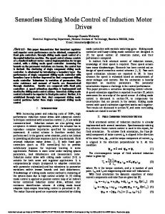
D. Implementation of the Discretized EKF Algorithm The structure of the EKF is shown in Fig. 1. The state estimates are obtained by the EKF algorithm in the following steps:
∂x
⎡1 h ( k + 1) = ⎢ ⎣0
[C d X ]x= x ( k +1) *
0
0
0
1
0
0
0⎤ 0 ⎥⎦
Step5: State vector estimation The state vector estimation (corrected state vector estimation, filtering) at time (k + 1) is performed as follows:
(9)
]
T
Xˆ (k +1) = X * (k +1) + K(k +1)[Y (k +1) − Yˆ(k +1)] Yˆ ( k + 1) = C X * ( k + 1) d
Step3: Covariance estimation of prediction The covariance matrix of prediction is estimated as
Pˆ (k + 1) = P* (k + 1) − K (k + 1)h(k + 1)P* (k + 1)
f is the gradient matrix. f (k + 1) = ∂
From Inverter
∂x +
B
w
+
∫
X
C
+
+
Vds Vqs
A
E. Tuning of the Covariance Matrices The tuning of the EKF involves an iterative modification of the covariance in order to yield the best estimates of the states [6]. Changing the covariance matrices Q and R affects both the transient and steady state operation of the filter. Increasing Q corresponds to stronger system noises or larger uncertainty in the machine model used. If the covariance R is increased, this corresponds to the fact that the measurements of the currents are subjected to a stronger noise and should be weighted less by the filter. Thus the filter gain matrix elements will decrease and this results in slower transient performance. The initial values of Q and R are selected randomly and tuned accordingly. From experience, the value of Q55 is chosen higher than remaining elements in Q matrix and the values of R matrix elements are higher than Q matrix elements.
Actual Ids Iqs
Estimated wr
Machine
----------------------------------------------------------------------------------------------------EKF + BU + dX B C ∫ X Estimated + + e I ds I qs
AX
A
eK
K
Figure 1. Structure of EKF TLm ωrTLm TLm
T ⎡ 0 ⎢1 − * T s ⎢ T ⎢ 0 1− * ⎢ Ts ⎢ f (k + 1) = ⎢ TLm 0 ⎢ τr ⎢ TLm ⎢ 0 τr ⎢ ⎢⎣ 0 0
L's Lr TLm
L's Lr − TLm
L's Lr T 1−
L's Lrτ r
L's Lr
Tωr 0
⎤
φqr ⎥
L's Lrτ r − ωrTLm
τr
(16)
Put k = k + 1, X (k) = X (k −1) , P(k ) = P(k − 1) and go to step2. The EKF described above can be used to estimate the speed of an induction motor under both steady state and transient conditions.
(11)
V dX
(15)
Step7: Updation
[Ad X + Bd U ]x= xˆ (k +1)
+
(14)
Step6: Covariance matrix of estimation error The error covariance matrix is obtained from
(10)
P * ( k + 1) = f ( k + 1) Pˆ ( k ) f T ( k + 1) + Q
where,
(13)
− Tωr
Tφqr
T
Tφdr
1−
τr
0
1
⎥
φdr ⎥⎥ ⎥ ⎥ ⎥ ⎥ ⎥ ⎥ ⎥⎦
III. EKF IMPLEMENTATION The EKF algorithm is written in C language and the data required (direct and quadrature axes voltages and currents) for the estimation algorithm are obtained from Matlab. Using Mfile program the Matlab simulink block is linked with CCS. The digital values of voltages and currents are stored in a file.
where, © 2009 ACADEMY PUBLISHER
16
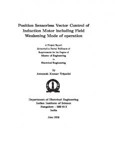
FULL PAPER International Journal of Recent Trends in Engineering, Vol 2, No. 5, November 2009 CCS C program takes the input data from Matlab workspace and it estimates the rotor speed. Depending upon the sampling time, the error in the estimated speed is minimized. Due to limitations in the memory size (when Matlab is linked with CCS in the simulator mode), only 32 Kbyte data can be processed. The sampling time is 0.002 sec. The flow diagram for EKF algorithm is shown in Fig.2. Number of samples taken is 4000 (N=4000). The estimated values are stored in the data memory and are plotted. Debugging is done with the help of disassembly window.
Motor Rating Output Poles Voltage Current Motor Speed Rs Rr Ls Lr Lm
3.7 kW 4 160 V 20 A 1500 rpm 0.3831 ohm 0.2367 ohm 33.34 mH 33.34 mH 32.11 mH
The estimated speed is compared with the actual speed and the error is given to PI controller which produces the required torque reference. From the estimated speed and the torque reference, the direct and quadrature axes reference currents are calculated. They are transformed to three phase quantities using inverse Park transformation. The reference three phase currents are compared with the actual currents. The error is given to the hysteresis current controller. Output of the controller produces the required control signal and it is given to the semiconductor switches. The output of the CRPWM drives the induction motor.
IV. SYSTEM CONFIGURATION The rating of the induction motor is given in Table I. The speed of an induction motor is estimated by EKF algorithm. The system configuration is shown in Fig.3. The estimated speed is used for overall control.
V. SIMULATION AND CCS RESULTS In this work, EKF algorithm is used to estimate the speed of the induction motor. Direct vector control method is applied to calculate the reference currents responsible for torque and flux. Simulations are carried out for speed reversal test, step change in load. A. Speed Reversal Test From the measured terminal voltages and currents the speed is estimated using EKF algorithm. Fig.4 shows the simulation and CCS results for a step change in speed. The sampling time is kept at 0.002 sec. Reducing the sampling time increases the accuracy and improves the drive performance. The algorithm is verified under low speed operations. Initially the reference speed is set at 50 rpm. At t = 3 sec, speed is reversed to –50 rpm. The simulation response is measured without a load. The deviation in the estimated speed by Matlab simulation and CCS is shown in Fig. 5 and it is around 4 rpm (8%). Clearly the estimated speed follows the speed command; and, as can be seen in Fig. 4, the estimated speed matches the actual rotor speed of the motor. It ensures that the motor speed is accurately estimated. Stator current and rotor fluxes are also estimated along with speed. Fig. 6 and 7 illustrate the estimated direct and quadrature axes stator currents by both Matlab and CCS. The estimated direct and quadrature axes rotor fluxes by both Matlab and CCS are shown in Fig.8 and 9.
Figure 2. Flow Chart for EKF Algorithm
Figure 3. System Configuration
TABLE I RATING AND PARAMETERS OF INDUCTION MOTOR
Figure 4. Speed response
© 2009 ACADEMY PUBLISHER
17
FULL PAPER International Journal of Recent Trends in Engineering, Vol 2, No. 5, November 2009 Figure 5. Deviation in the estimated speed by Matlab and CCS
Matlab and CCS. Fig. 16 and 17 illustrate the estimated direct and quadrature axes rotor flux.
Figure 10. Speed response
Figure 6. Direct axis stator current
Figure 11. Deviation in the estimated speed by Matlab and CCS
Figure 7. Quadrature axis stator current
Figure 12. Direct axis stator current
Figure 8. Direct axis rotor flux
Figure 13. Deviation in d-axis stator current by Matlab and CCS
Figure 9. Quadrature axis rotor flux
B. Step Change in Load The speed of the motor is maintained constant at 50 rpm. At t = 0, the load torque is zero and at t = 3 sec, a load of 2.5 Nm is applied to the motor. The speed response is shown in Fig. 10 and the deviation in the estimated speed by CCS and Matlab is shown in Fig. 11. The estimated direct axis stator current and the deviation in the estimated current by CCS and Matlab are depicted in Fig.12 and 13. In the CCS program, all the mathematical calculations are performed and values are used directly with three digit approximation to make the program simple but in Matlab the variables are declared directly and there are no hand mathematical calculations involved. This makes some deviation in the estimated speed by Matlab and CCS. Fig. 14 and 15 illustrate the estimated quadrature axis stator current and the deviation in the estimated current by © 2009 ACADEMY PUBLISHER
Figure 14. Quadrature axis stator current
Figure 15. Deviation in q- axis stator current by Matlab and CCS
18
FULL PAPER International Journal of Recent Trends in Engineering, Vol 2, No. 5, November 2009 [4]
[5]
[6]
[7]
Figure 16. Direct axis rotor flux
Figure 17. q- axis rotor flux
The difference between the estimated speed by CCS and Matlab is shown in Fig.11 and it is less than 1 rpm (around 0.5%). The difference between the estimated stator current (both d-axis and q-axis) by CCS and Matlab is illustrated in Fig.13 and Fig.15 and its average value is approximately 0.5 amp (error is 2%). VI. CONCLUSION As an estimator, the Extended Kalman filtering technique is investigated to observe the rotor speed. For this purpose, appropriate mathematical model of induction machine is studied and discretized for real-time applications. Several simulations are illustrated to examine the performance of EKF. The oscillation in the estimated speed is reduced by decreasing the initial values of the covariance matrices. It is also verified by Code Composer Studio version 2.2 to implement the EKF algorithm in real time. The algorithm can be verified using TMS320F2812 DSP processor. The mathematical complexity and difficulty of EKF is a significant disadvantage when compared to Luenberger observer. And for practical cases where the uncertainties are significant, EKF will provide better state estimation. REFERENCES [1]
[2]
[3]
B. K. Bose, Modern Power Electronics and AC drives, Upper Saddle River, N. J. Prentice Hall, Third edition, 2003, pp.388-400 and pp.348350. Bozo Terzic and Martin Jadric, “Design and implementation of Extended Kalman Filter for the speed and rotor position estimation of Brushless DC motor”, IEEE transactions on Industry Electronics, Vol.48, No.6, 2001, pp.1065-1073. Peter Vas, “Sensorless vector and direct torque control”, Oxford University Press, 1998, pp.470-491.
© 2009 ACADEMY PUBLISHER
19
Young-Real Kim, Seung-Ki Sul, Min-Ho Park, “Speed sensorless vector control of an Induction Motor using an Extended Kalman Filter” IEEE Transactions on Industry Applications, Vol.30, No.5, 1994, pp.594-599. Hisao Kubota, Kouki Matsuse and Takayoshi Nakano, “DSP based speed adaptive flux observer of induction motor”, IEEE transactions on Industry Applications, Vol.29, No.2, 1993, pp.344-348. K.Matsuse, Y.Kouno,H.Kawai and J.Oikawa, “ Characteristics of speed sensor-less vector controlled dual induction motor drive connected in parallel fed by a single Inverter”, IEEE Trans. Ind. Applications., vol. 40, pp. 153-161, Jan./Feb. 2004. K. Matsuse, Y. Kouno, H. Kawai and S. Yokomizo, “A speed-sensor-less vector control method of parallel-connected dual induction motor fed by a single inverter,” IEEE Trans. Ind. Applications., vol. 38, pp. 1566– 1571, Nov./Dec. 2002.