Paper Title: Single Chip for Imaging, Color Segmentation, Histogramming and Pattern Matching Authors: Ralph Etienne-Cummings1,2, Philippe Pouliquen1,2, M. Anthony Lewis1 Affiliation: 1
Iguana Robotics, Inc., P.O. Box 628, Mahomet, IL 61853, USA Voice: 217-586-7849 FAX: 217-573-2273 e-mail:
[email protected]
2
Departement of Electrical and Computer Engineering, Johns Hopkins University, 3400 N. Charles Street, Baltimore, MD 21218 USA Voice: 410-516-3494 FAX: 410-516-5566 e-mails:
[email protected],
[email protected] Corresponding Author & Speaker:
Ralph Etienne-Cummings Dept. of ECE/JHU 105 Barton Hall 3400 N. Charles Street Baltimore, MD 21218 Voice: 410-516-3494 FAX: 410-516-5566
ISSCC 2002
1
9/4/2001
Single Chip for Imaging, Color Segmentation, Histogramming and Pattern Matching Ralph Etienne-Cummings1,2, Philippe Pouliquen1,2, M. Anthony Lewis1 1 Iguana Robotics, Inc., Mahomet, IL 61853 2 Dept. of ECE, Johns Hopkins University, Baltimore, MD 21218 128(H) x 64(V) x RGB CMOS imager is integrated with region-of-interest selection, RGB-to-HSI transformation, HSI-based pixel segmentation, 36-bins x 12bits HSI histogramming and sum-ofabsolute-difference template matching. 32 learned color templates are stored and compared to each image. Running at 30fps, it uses 1mW.
ISSCC 2002
2
9/4/2001
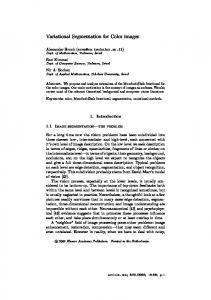
Single Chip for Imaging, Color Segmentation, Histogramming and Pattern Matching Ralph Etienne-Cummings1,2, Philippe Pouliquen1,2, M. Anthony Lewis1 1 Iguana Robotics, Inc., Mahomet, IL 61853 2 Dept. of ECE, Johns Hopkins University, Baltimore, MD 21218 A 128(H) x 64(V) x RGB CMOS imager is integrated with mixed signal processing circuitry to realize focal-plane region-of-interest selection, RGB-to-HSI transformation, HSI-based segmentation, 36bins HSI histogramming and sum-of-absolute-difference (SAD) template matching. This self-contained color imaging and processing chip, designed as a front-end for micro-robotics, toys and “seeing-eye” computers, learns the identity of objects through their color signature. The signature is composed of a 36-bins x 12-bits HSI histogram template. The template is stored at the focal-plane during a learning step. During the recognition step, newly acquired images are compared to 32 stored templates using a SAD computer. The minimum SAD result indicates the closest match. In addition, the chip can be used to segment a color image and identify regions in the scene having particular color characteristics. The location of the matched regions can be used to track objects in the environment. Figure 1 shows a block diagram of the chip. Figure 6 shows a chip layout (the layout is shown because the light shielding layer obscures the details). Table I shows the specifications of the chip. This chip represents the first self-contained color processing imager with focal-plane segmentation, histogramming and template matching capabilities. In the imager array, three currents, corresponding to R,G and B, values are sampled-and-held for each pixel (a color filter wheel is used in this prototype). To facilitate processing, a current mode imaging approach is adopted. This also provides more than 120dB of dynamic range [1], allows RGB scaling for white correction using a multiplying DAC, and RGB normalization using a translinear circuit [2]. The normalization guaranties that a large dynamic range of RGB currents are resized for the HSI transformer to operate correctly. However, it limits the speed of operation to approximately 30 fps because the transistors must operate in subthreshold. For read-out, the pixels can be grouped into blocks of 1x1 (single pixel) to 128 x 64 (entire array). The blocks can be advanced across the array in single or multiple pixel intervals. The organization of the pixels and the scanning methods are programmable by loading bit patterns in two scanning registers, one for scanning pixels within blocks and the other for scanning the blocks across the array. Figure 2 shows the schematic of the pixel, a portion of the RGB normalizer and a sample image. The output currents of the pixel are amplified using tilted mirrors, where Vdd_d < Vdd_m. The reset switch is included to accelerate the offtransition of the pixel. Not shown in figure 2(b) is the scaling circuit, which simply multiplies the RGB components by programmable integer coefficients from 1 - 16. The image in figure 2(c) has been white corrected using the scaling circuit and shows the mismatch that is typical for current mode imagers. The RGB-to-HSI transformer uses an opponent color formulation, reminiscent of biological color processing [3]. The intensity (I) is obtained before normalization by summing the RGB components (see figure 2(b)). Saturation (S) is computed by subtracting the minimum of the normalized RGB values from the sum. Hue (H) is given by the arctan[0.866*(g-b)/(2r-g-b)], where rbg are the normalized RGB values [4]. Due to the complexity of computing this function, an analog look-up table is used. We use a hybrid circuit that simply correlates (g-b) and (2r-g-b) and indicates which
ISSCC 2002
3
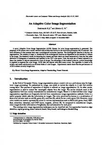
Hue interval corresponds the RGB values. The (g-b) and (2r-g-b) components are each quantized into 16 levels using a thermometer code 4bit analog-to-digital conversion. The look-up table maps the 18 x 18 (the quadrant is given by the signs of the components) input combinations into 36 Hue intervals, each having 10 degrees resolution, to cover the 360 degrees of Hue space. The HSI computation is applied to each RGB value scanned from the array; color segmentation is realized by testing each pixel’s HSI values against prescribed values, and the appropriate label is applied to the pixel. Figure 3 shows the schematic of the Saturation and Hue computation circuits. A loser-take-all circuit is used to find the minimum rgb component for the Saturation (S) value. The mapping of rgb values in Hue bins uses a ROM decoder. Figure 4 shows the measured relationship between input Hue angle and bin allocation. The plot is obtained by presenting known values of RGB (i.e. Hue angle) to the chip and recording the Hue bins that are triggered. There are some overlaps in the response ranges of the individual bins because of analog imprecision in creating the Hue table’s input addresses. Notice, however, that the overlaps are desirably restricted to nearest neighbor bins. Also shown in figure 4 is the pixel color segmentation result for a test image of a Rubik’s cube. To test the processing unit in isolation, we piped in an external image. The figure shows that the chip clusters parts of the image with similar HSI components into similar bins. The HSI histogramming step is performed using 36, 12-bit counters to measure the number of pixels that fall within each prescribed HSI interval. After the scanning of the imager is completed, the counters hold the color signature of the scene. During the learning phase, the signature is transferred to one of the 32 on-chip array of SRAM template cells. During the matching phase, the newly acquired signatures are compared to the stored templates, using 8 serial presentations of 4 parallel templates, with the SAD cells. The resultant error for each template is presented off chip, where they can be sorted using a simple micro-controller such as a PIC, to find the best match template. Figure 5 shows an example of template matching, where the color signature of parts of cans are “learned” and subsequently localized in a scene containing multiple cans. The learned segment is 15 x 15; during matching, the image is scanned in blocks of 15 x 15, shifted by 8 pixels. No scanned block matches the learned block exactly. A plot of the SAD error is also shown. Match threshold is set to 155. The prototype demonstrates that a real-time color segmentation and recognition system can be implemented using a small silicon area and small power budget. By using a fabrication technology with RGB filters, the entire system can be realized with a tiny footprint for compact imaging/processing applications. Acknowledgements: This work was supported by an NSF SBIR award to Iguana Robotics, Inc. We thank Frank Tejada and Marc Cohen for their help with chip testing. References: [1] C. Mead, “Sensitive Electronic Photoreceptor,” Proc. 1985 Chapel Hill Conf. VLSI, pp. 463-471, Computer Science Press, Maryland, 1985. [2] B. Gilbert, "Translinear Circuits. 25 Years On Part I. The Foundations," Electronic Engineering (London), Vol. 65, No. 800, Aug 1993. [3] F. Perez and C. Koch, "Towards Color Image Segmentation in Analog VLSI: Algorithms and Hardware," Int. J. Computer Vision, Vol. 12, No. 1, pp. 17-42, 1994. [4] R. Gonzalez and R. Woods, Digital Image Processing, Addison-Wesley Publishing Company, 1992.
9/4/2001
TABLE I: SUMMARY OF PERFORMANCE Technology Array Size (R,G,B)
0.5µm 3M CMOS 128 (H) x 64 (V)
Chip Area Pixel Size
4.25mm x 4.25mm 24.85µm x 24.85µm
Fill Factor
20%
FPN
~5%
Dynamic Range
>120 dB (current mode)
Region-Of-Interest Size
1 x 1 to 128 x 64
Color Current Scaling
4bits
Hue Bins
36, each 10 degree wide
Saturation
Analog (~5bits) one threshold
Intensity
Analog (~5bits) one threshold
Histogram Bin Counts
12bits/bin
Template Size
432bits (12 x 36bits)
No. Stored Template Template Matching (SAD) Frame Rate
32 (13.8Kbits SRAM) 4 Parallel SAD, 18bits results Array Scan: ~2K fps HIS Comp: ~30 fps ~1mW @ 30 fps on 3.3V Supplies
Power Consumption
Figure 1: Block diagram of chip.
Figure 2: A) Schematic of the pixel. B) Schematic of the normalization circuit. C) Sample image.
Figure 3: A) Schematic of Saturation circuit. B) Hue look-up table. 450
Template Matching Results
400
360 300
350
240
300
SAD Value
Theoretical Hue Value [degrees]
R G B-to -HS I T ran sfo rm atio n
180 120
250 200
60
150
0
100 0
5
10
15
20
25
30
35
Matching threshold
50
C h ip C om pu ted H ue B in s [1 0 degrees resolution]
105
92
79
66
53
40
27
14
1
0 Image Segment Block Index
Figure 5: Template learning and matching.
Figure 4: HSI based pixel segmentation of test image.
ISSCC 2002
4
9/4/2001
Figure 6: Chip layout (light shield layer obscures all details in micrograph).
ISSCC 2002
5
9/4/2001