Computer Standards & Interfaces 36 (2014) 889–898
Contents lists available at ScienceDirect
Computer Standards & Interfaces journal homepage: www.elsevier.com/locate/csi
Software and hardware certification of safety-critical avionic systems: A comparison study Wonkeun Youn ⁎, Baeck-jun Yi 1 Aerospace Safety & Certification Center, Korea Aerospace Research Institute, 169-84 Gwahangno Yuseong-gu, Deajeon 305-806, Republic of Korea
a r t i c l e
i n f o
Article history: Received 15 November 2012 Received in revised form 7 January 2014 Accepted 20 February 2014 Available online 13 April 2014 Keywords: Software and hardware quality assurance Airborne software and hardware Safety certification DO-178B DO-254
a b s t r a c t To ensure the safety of avionic systems, civil avionic software and hardware regulated by certification authorities must be certified based on applicable standards (e.g., DO-178B and DO-254). The overall safety integrity of an avionic system, comprising software and hardware, should be considered at the system level. Thus, software and hardware components should be planned, developed and certified in a unified, harmonized manner to ensure the integral safety of the entire avionic system. One of the reasons for the high development costs of avionic systems complying with standards may be a lack of sufficient understanding of how to employ these standards efficiently. Therefore, it is important to understand the similarities and differences between DO-178B and DO-254 to effectively manage the processes required by these standards, to minimize cost, and to ultimately ensure the safety of the entire avionic system. Thus, the goal of this paper is to compare various aspects of DO-178B and DO254 comprehensively. The paper may serve as a useful supplementary material for the practitioner to understand the rationales behind and the differences between two main standards used in avionic industries. © 2014 Elsevier B.V. All rights reserved.
Contents 1. 2. 3. 4. 5. 6.
Introduction . . . . . . . . . . . . . . . . . . . . . . . . . . . . . . . . . . . Software and hardware characteristics . . . . . . . . . . . . . . . . . . . . . . . Software considerations in airborne systems and equipment certification (RTCA DO-178B) Design assurance guidance for airborne electronic hardware (RTCA DO-254) . . . . . . Similarities between DO-178B and DO-254 . . . . . . . . . . . . . . . . . . . . . Differences between DO-178B and DO-254 . . . . . . . . . . . . . . . . . . . . . 6.1. Objectives . . . . . . . . . . . . . . . . . . . . . . . . . . . . . . . . . 6.2. Independence . . . . . . . . . . . . . . . . . . . . . . . . . . . . . . . 6.3. Design assurance . . . . . . . . . . . . . . . . . . . . . . . . . . . . . . 6.4. Life cycle process/data . . . . . . . . . . . . . . . . . . . . . . . . . . . 6.4.1. Development (design) process . . . . . . . . . . . . . . . . . . . 6.4.2. Verification process and validation process . . . . . . . . . . . . . . 6.4.3. Deviation process . . . . . . . . . . . . . . . . . . . . . . . . . 6.4.4. Standards . . . . . . . . . . . . . . . . . . . . . . . . . . . . . 6.4.5. Minimal data submission . . . . . . . . . . . . . . . . . . . . . . 6.5. Tool qualification . . . . . . . . . . . . . . . . . . . . . . . . . . . . . . 6.6. COTS (commercial-off-the-self) components . . . . . . . . . . . . . . . . . 7. Software and hardware as parts of the system . . . . . . . . . . . . . . . . . . . . 8. Summary . . . . . . . . . . . . . . . . . . . . . . . . . . . . . . . . . . . . . Acknowledgments . . . . . . . . . . . . . . . . . . . . . . . . . . . . . . . . . . . References . . . . . . . . . . . . . . . . . . . . . . . . . . . . . . . . . . . . . . .
⁎ Corresponding author. Tel.: +82 42 870 3542; fax: +82 42 870 2501. E-mail addresses:
[email protected] (W. Youn),
[email protected] (B. Yi). 1 Tel.: +82 42 860 2502; fax: +82 42 870 2501.
http://dx.doi.org/10.1016/j.csi.2014.02.005 0920-5489/© 2014 Elsevier B.V. All rights reserved.
. . . . . . . . . . . . . . . . . . . . .
. . . . . . . . . . . . . . . . . . . . .
. . . . . . . . . . . . . . . . . . . . .
. . . . . . . . . . . . . . . . . . . . .
. . . . . . . . . . . . . . . . . . . . .
. . . . . . . . . . . . . . . . . . . . .
. . . . . . . . . . . . . . . . . . . . .
. . . . . . . . . . . . . . . . . . . . .
. . . . . . . . . . . . . . . . . . . . .
. . . . . . . . . . . . . . . . . . . . .
. . . . . . . . . . . . . . . . . . . . .
. . . . . . . . . . . . . . . . . . . . .
. . . . . . . . . . . . . . . . . . . . .
. . . . . . . . . . . . . . . . . . . . .
. . . . . . . . . . . . . . . . . . . . .
. . . . . . . . . . . . . . . . . . . . .
. . . . . . . . . . . . . . . . . . . . .
. . . . . . . . . . . . . . . . . . . . .
. . . . . . . . . . . . . . . . . . . . .
. . . . . . . . . . . . . . . . . . . . .
. . . . . . . . . . . . . . . . . . . . .
. . . . . . . . . . . . . . . . . . . . .
. . . . . . . . . . . . . . . . . . . . .
. . . . . . . . . . . . . . . . . . . . .
. . . . . . . . . . . . . . . . . . . . .
. . . . . . . . . . . . . . . . . . . . .
890 890 891 891 891 893 893 893 893 893 893 894 894 895 895 895 895 895 897 898 898
890
W. Youn, B. Yi / Computer Standards & Interfaces 36 (2014) 889–898
1. Introduction Over the past several decades, safety has been a critical issue in many embedded applications in aerospace, aircraft, road vehicles, railways, nuclear systems, and implanted devices because the failure/malfunction of a safety-critical system may cause catastrophic damage or loss of life [1]. Society has the obligation to protect itself, and governments and industry organizations have established guidelines and standards for engineers to follow in developing systems in these areas. In particular, the introduction of such guidelines and standards started relatively early in the aviation industry due to the serious consequences of aircraft-related accidents. To ensure that newly developed aircraft systems are designed and built to comply with applicable regulations and the highest levels of safety integrity, certification is mandatory in every country before a new aircraft system is put into operation. The definition of certification is the “procedure by which a third-party gives written assurance that a product, process, or service conforms to specified requirements [2].” For example, every country needs to certify new aircraft to assure compliance with applicable airworthiness requirements before it is cleared for flight. This procedure is known as type certification; a certification authority approves one sample of the developed system for flight usage [3]. Modern safety-critical systems for avionics utilize not only an increasing amount of sophisticated software but also a softwareembedded hardware to process the large amount of data needed to control avionic systems and monitor their current status [4]. Avionics safety is considered at the system level and has no important implications when considered separately with regard to software and hardware [5]. The failure or malfunction of software can be due to interactions with hardware. Additionally, software and hardware domains have mutual influence on each other during aviation system development. Consequently, the software and hardware components of safety-critical systems must be developed and certified in a unified manner to ensure the integral safety of the entire avionic system [4]. To assure the reliability of the software/hardware and to ultimately ensure the safety of passengers, the U.S. Federal Aviation Administration (FAA) requires software/hardware certification suited to the development of safety-critical systems [6]. The FAA accepts standards developed by the Radio Technical Commission for Aeronautics (RTCA) for the reliability and safety that are vital in this field: Software Considerations in Airborne Systems and Equipment Certification (DO-178B) for software [7] and Design Assurance Guidance for Airborne Electronic Hardware (DO-254) for hardware [8]. DO-178B and DO-254 prescribe the design assurance guidance for airborne software and hardware, respectively. Although the implementation of DO-178B and DO-254 is not a mandatory regulation, DO-178B and DO-254 have been widely accepted in civil aviation [5]. However, it has been reported that DO-178B and DO-254 have several inadequate and ambiguous standards, such as ambiguity about the concept of low-level requirements and inconsistent terminologies [2]. According to applicants [4], the relative ambiguity and flexibility of these guidelines cause significantly different interpretations and implementations. Additionally, compliance with DO-178B and DO-254 guidelines in software development and hardware design is often considered as contributing to the high expense of commercial aviation systems because the guidelines require rigorously iterative processes and extensive documentation. However, the high cost may often be due to a lack of sufficient understanding of how to efficiently implement these standards [9]. Although there have been a number of studies exploring software and hardware guidelines [10–12], there have been few studies reviewing the similarities and differences between DO-178B and DO-254. It is important to understand DO-178B and DO-254 and how their processes differ to avoid potentially unnecessary work; this understanding will minimize the expense of development while ultimately ensuring the integral safety
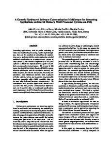
of the avionics at the system level. Therefore, the goal of this study is to present a comprehensive comparison study of various aspects of the software and hardware guidelines. This paper is organized as follows. Section 2 outlines general software and hardware characteristics. Sections 3 and 4 present brief general overviews of DO-178B and DO-254, respectively. Section 5 discusses the specific similarities between DO-178B and DO-254, and Section 6 provides a detailed discussion of the differences. Finally, our conclusions are summarized in Section 7. 2. Software and hardware characteristics Although there are some similarities between software development and hardware manufacture, they are basically different [13]. In essence, software is a logical system, whereas hardware is a physical system. Hardware and software are interconnected and require each other, and neither can be realistically used without the other. In particular, it is the norm in modern avionics that the desired end functionality is implemented using hardware (a microprocessor) running complex computer software. The reliability of software is a difficult issue, and there are even issues in defining software reliability (e.g., failure rate) quantitatively [3]. Moreover, it is impossible to test even the simplest software completely because the number of possible inputs, outputs, and paths through software is extremely large. In contrast, although there are several exceptions, in most cases, hardware reliability can be measured quantitatively by means of statistical and operational testing [14]. Fig. 1 shows failure rates as a function of time for software and hardware. Both software and hardware exhibit relatively high failure rates at the beginning of their service; defects are found and corrected, and the failure rate drops to a steady-state level for some period of time. Over time, however, the failure rate of hardware rises as hardware components are adversely affected by environmental phenomena, such as the cumulative effects of dust, vibration, abuse, temperature extremes or electromagnetic fields. In contrast, software is not susceptible to these problems because software does not physically fail as hardware does [15]. In practice, however, software will undergo changes
Fig. 1. Software and hardware failure rates.
W. Youn, B. Yi / Computer Standards & Interfaces 36 (2014) 889–898
4. Design assurance guidance for airborne electronic hardware (RTCA DO-254)
Table 1 Software and hardware characteristics. Concept
Software
Hardware
Design
Logical system
Failure cause
Design flaw
Deterioration Time-dependent Failure rate
No No Not quantifiable (quantifiable under extreme limitations) Yes, but more complex than hardware maintenance
Physical system Design flaw Manufacturing defects Wear and tear Yes Yes Quantifiable
Maintenance
891
Yes
RTCA document DO-254, Design Assurance Guidance for Airborne Electronic Hardware, was released on April 19, 2000, and formally recognized as an acceptable means of compliance by the FAA at the beginning of 2005. DO-254 documents a consensus of the aviation community concerning the design assurance of airborne electronic hardware. The purpose of DO-254 is “to assist organizations by providing design assurance guidance for the development of airborne electronic hardware such that it safely performs its intended function, in its specified environments [8].” The DO-254 guidance is applicable to, but not limited to: 1. Line Replaceable Units (LRUs)
(maintenance) during its life cycle. As changes are made, it is likely that some new defects will be introduced, causing the failure rate curve to spike as shown in Fig. 1(B). Before the curve can return to the original steady-state failure rate, another change may be requested, causing the curve to spike again. Slowly, the failure rate level begins to rise — the software is deteriorating due to change. Lastly, if hardware wears out or fails, it can be replaced by spare parts. However, there are no software spare parts, and software failure is attributable to an error in design; thus, software maintenance is inherently more complex than hardware maintenance [15]. The similarities and differences of software and hardware characteristics are summarized in Table 1.
3. Software considerations in airborne systems and equipment certification (RTCA DO-178B) DO-178B, Software Considerations in Airborne Systems and Equipment Certification, is a document developed by the Radio Technical Commission for Aeronautics (RTCA) and was released on December 1, 1992. Its purpose is “to provide guidelines for the production of software for airborne systems and equipment that performs its intended function with a level of confidence in safety that complies with airworthiness requirements.” DO-178B documents a consensus of the aerospace industry regarding the approval of airborne software [3]. DO-178B primarily focuses on the production processes; it is an evidence-based approach and does not address any specific life-cycle model [12]. These processes are divided into three categories (see Fig. 2): a software planning process; a software development process, including software requirements, software design, software coding, and integration; and an integral process, including software verification, software configuration management, quality assurance, and certification liaison. Because DO-178B is not mandatory or a regulation, an applicant can propose another basis of certification.
2. Circuit Board Assemblies 3. Custom micro-coded components, such as Application Specific Integrated Circuits (ASICs) and Programmable Logic Devices (PLDs), including any associated macro functions 4. Integrated technology components, such as hybrids and multi-chip modules 5. Commercial-Off-The-Shelf (COTS) components. Similar to DO-178B, DO-254 is mainly a process-oriented document; it is a method of process assurance and does not prescribe any particular life-cycle model. The processes are divided into three categories (see Fig. 3): a hardware planning process; a hardware design process, including requirements capture, conceptual design, detailed design implementation, and a production transition process; and an integral process (or supporting process), including validation and verification, configuration management, process assurance, and certification liaison. Because DO-254 is not a requirement, other means of certification provided by applicants may be acceptable to certification authorities. In DO-254, a hardware item is classified as simple if a set of comprehensive tests can be developed to prove its correct functionality under all foreseeable operating conditions, with no anomalous behavior [8]. An item that cannot be identified as simple should be identified as complex. For a simple hardware item, no further application of DO254 is required. 5. Similarities between DO-178B and DO-254 The structure and content of DO-178B and DO-254 are similar in many respects because they were developed by almost the same committee. Both DO-178B and DO-254 were developed to serve as a means of compliance to the Code of Federal Regulations (CFR) Title 14 “Aeronautics and Space,” parts 23 (normal, utility, acrobatic, and commuter category airplanes), 25 (transport category), 27 (rotorcraft
Fig. 2. The software lifecycle described in DO-178B.
892
W. Youn, B. Yi / Computer Standards & Interfaces 36 (2014) 889–898
Fig. 3. The hardware lifecycle described in DO-254.
category), 29 (rotorcraft transport category), and 33 (aircraft engines). Within the CFR, each of these parts has subparts .1301 and .1309. Thus, complying with DO-178B and DO-254 is equivalent to complying with the CFRs; both are tied to the system and safety assessment process (xx.1301 and xx.1309; ARP 4754 and ARP 4761). However, although most airborne applicants use DO-178B and DO-254 as their means of compliance for software and hardware, respectively, DO178B and DO-254 are “a means but not the only means” for complying with the regulations. Fig. 4. indicates DO-178B and DO-254 as a means of compliance to the applicable CFR, along with the other types of policy and guidance documents that clarify its interpretations. The safety criticality of both DO-178B and DO-254 is established at the system level using a system safety assessment process based on the failure conditions associated with software and hardware components, respectively. The safety conditions are divided into five categories: ‘Catastrophic’, ‘Hazardous/severe-major’, ‘Major’, ‘Minor’, and ‘No effect’. The DO-178B and DO-254 guidance then determines five different assurance levels that relate to the above categorization of failure conditions (Levels A to E). Level A is the most rigorous, where a Catastrophic failure causes the total loss of plane and passengers, followed by Hazardous/severe-major failure at Level B, where a small number of passengers may die, and Major failure at Level C, where failure can
cause passengers to suffer major injury or discomfort. At Level D, there can be minor injuries, and Level E has no effect on flight safety. More detailed information, including the safety conditions corresponding to assurance levels and FAR/JAR failure-probability, is provided in Table 2. As described in Sections 3 and 4, both DO-178B and DO-254 are process-oriented; certification does not mainly focus on the assessment of the completed resulting system but rather on the evaluation of a set of artifacts provided by applicants [16]. In both DO-178B and DO-254, there are three main processes: a planning process, development process (design process), and integration (correctness or supporting) process. The planning process must be completed first. Development follows planning, whereas the integration process (supporting process) is performed iteratively from project start to finish. More specifically, both documents are centered around life cycle phases: planning, development, verification, configuration management, quality/process assurance, and certification liaison. Both documents specify an evidence-based approach for supporting certification and require extensive and thorough life-cycle data documentation. Both are requirements-centric and enforce requirementsbased testing. Both strive to ensure no unintended functionality. Both address tool qualification, though the criteria for when a tool needs to
Fig. 4. Regulation, DO-178B, DO-254, and related policy.
W. Youn, B. Yi / Computer Standards & Interfaces 36 (2014) 889–898
893
Table 2 DO-178B/DO-254 safety criticality overview (ARP4761 and AC25.1309). Level
System failure
Description
FAR/JAR failure-probability definition (P = probability)
A B
Catastrophic Hazardous/severe-major
P b 10−9 10−9 b P b 10−7
C
Major
D
Minor
E
No effect
All failure conditions that prevent continued safe flight and landing Large reduction in safety margins Crew cannot perform tasks Adverse impact on occupants Significant reduction in safety Increased workload, crew is inefficient Discomfort to occupants Slight reduction in safety Slight increase in crew workload Inconvenience to occupants No effect on the operation of the aircraft
be qualified are different. Lastly, lifecycle data are created throughout the lifecycle process, and the characteristics of lifecycle data are the same in both DO-178B and DO-254, as follows [7,8]. ✓ Unambiguous: a single, unique interpretation. ✓ Complete: all necessary requirements and materials are defined along with the associated data. ✓ Verifiable: a method to determine the correctness of the data exists. ✓ Consistent: no contradicting data exist. ✓ Modifiable: the data are structured and have a style such that changes can be made consistently without a change in structure. ✓ Traceable: the origin of the data can be tracked.
6. Differences between DO-178B and DO-254 Although DO-254 is the counterpart to the well-established software standard DO-178B and loosely parallels it, as described in the previous sections, there are several distinct differences. The detailed differences are as follows.
10−7 b P b 10−5
10−5 b P
N/A
6.3. Design assurance Although the software/hardware levels of both DO-178B and DO254 are determined by the system safety assessment process, DO-254 allows functional failure path (FFP) analysis to determine the proper design assurance for each path; in contrast, FFP analysis is not addressed in DO-178B. The FFP analysis in DO-254 is a structured, top-down, repeating analysis that identifies functional paths and associated failure modes [8]. The data resulting from the FFP analysis is then used to determine means of implementing function and design assurance FFPs for Levels A and B. Furthermore, for DO-254, once the hardware is determined to be simple, no further implementation of DO-254 is required. If the hardware is Level D, implementation of DO-254 is optional, and other means of compliance can be applied to the product. For Level C, the application of DO-254 is necessary. For Levels A and B, the implementation of DO-254 and verification with independence are required, and the additional design assurance strategies described in DO-254 Appendix B are necessary also. This is diagrammed in Fig. 5. 6.4. Life cycle process/data
6.1. Objectives
6.2. Independence
The applicant should submit software/hardware data produced during the life cycle to demonstrate compliance with DO-178B or DO-254 (summarized in Table 4). There are 20 different lifecycle data items in DO-178B and 27 in DO-254. In general, the lifecycle data of DO-254 are similar to those of DO-178B; for example, PHAC and HAS are the same as PSAC and SAS, respectively, and the development plan, verification plan, and configuration management plan are similar. The process assurance plan of DO-254 is also similar to the quality assurance plan of DO-178B. However, there are several distinct lifecycle process/data differences, as follows.
The definition of independence is “the separation of responsibilities which ensure the accomplishment of object evaluation.” Independence can be accomplished by another individual, not by the developer, evaluating the correctness of data or the compliance of a process. For DO178B, independence is well defined by objective and software level in Table 3. The number of objectives with independence increases with the software level (except for Levels C and D). However, for DO-254, independence is required only at Levels A and B; Level C and lower do not mandate independent verification (Appendix A of DO-254).
6.4.1. Development (design) process DO-178B defines four main development processes, requirements, design, coding, and integration, whereas DO-254 defines five major design processes, requirements capture, conceptual design, detailed design, implementation, and production transition. Because manufacturing is a concern for DO-254, it requires acceptance testing and hardware acceptance test criteria in lifecycle data, though conducting tests is beyond its scope. Additionally, a production transition process to ensure availability and suitability for production is included in the hardware design
The objectives are well defined specifically by software level in DO178B and are summarized in Table 3. In DO-178B, there are 66 objectives applicable for Level A, 65 objectives for Level B, 57 objectives for Level C, 28 objectives for Level D, and none for Level E. Unlike DO178B, the objectives in DO-254 are not clearly defined by hardware level and are not obvious compared to DO-178B.
Table 3 DO-178B failure condition, number of objectives, and independence of design assurance level.
Failure condition due to S/W anomalous behavior # of objectives # of objectives with independence
Level A
Level B
Level C
Level D
Level E
Catastrophic 66 25
Hazardous 65 14
Major 57 2
Minor 28 2
No effect – –
894
W. Youn, B. Yi / Computer Standards & Interfaces 36 (2014) 889–898
Fig. 5. Design assurance consideration for DO-254.
process of DO-254. Manufacturing is not a matter of interest for DO-178B, thus data relevant to manufacturing are not included in its lifecycle data. 6.4.2. Verification process and validation process DO-178B defines two types of coverage: requirements coverage analysis and structural coverage analysis. Requirements coverage Table 4 Software/hardware life cycle data. DO-178B lifecycle data (20 items)
* Must be submitted to certification authority
*Plan for software aspect of certification Software development plan Software verification plan
Source code Executable object code Software verification cases and procedures Software verification results Software life cycle environment configuration index *Software configuration index Problem reports Software configuration management records Software quality assurance records *Software accomplishment summary
Software configuration management plan Software quality assurance plan Software requirement standards Software design standards Software code standards Software requirements data Design description DO-254 lifecycle data (27 items)
* Must be submitted to certification authority
*Plan for hardware aspect of certification Hardware development plan Hardware validation plan Hardware verification plan Hardware configuration management plan
Assembly drawings Installation control drawings Hardware/Software interface data Hardware traceability data Hardware review and analysis procedures Hardware review and analysis results Hardware test procedures Hardware test results Hardware acceptance test criteria Problem reports Hardware configuration management records Hardware process assurance records Hardware accomplishment summary
Hardware process assurance plan Hardware design standards Requirements standards Validation and verification standards Hardware archive standards Hardware requirements Conceptual design data Detailed design data *Top-level drawing
* indicate that life cycle data must be submitted to certification authority.
analysis examines the completeness and adequacy of requirementbased testing for verifying the implementation of the requirements [7]. Structural coverage analysis determines which code structures were not exercised by the requirement-based test procedures; it demonstrates that the code structure was confirmed for the applicable software level and supports a demonstration of the absence of unintended and untested functionality. The rigor of structural coverage analysis varies by software level, as follows: ✓ ✓ ✓ ✓
Level D — not required. Level C — statement coverage. Level B — statement and decision-condition coverage. Level A — statement, decision-condition, modified condition/decision coverage (MC/DC).
For DO-254 Level A/B function, design assurance confidence can be accomplished by the implementation of various methods, such as architectural mitigation, product service experience, and advanced verification methods, including elemental analysis, formal methods, and safety-specific verification analysis presented in DO-254 Appendix B. Elemental analysis in DO-254 for Level A/B function is the counterpart to and adaptation of DO-178B's structural coverage analysis. It ensures that all elements are verified by requirement-based test cases and serve as a completion criterion of the verification from a bottom-up perspective. Additionally, robustness test cases to demonstrate how software responds to abnormal inputs should be performed in DO-178B (except for Level D); robustness testing is optional, depending on the project, in DO-254. DO-254 addresses validation that the derived requirements are correct and complete with respect to system requirements [8] and requires a hardware validation plan as lifecycle data for the derived requirements based on selected hardware. In contrast, DO-178B pushes validation to the system level. Thus, a software validation plan is not addressed in lifecycle data. 6.4.3. Deviation process In DO-178B, only the software accomplishment summary (SAS) should include deviations from the plans and standards. Section 11.20, item k (software accomplishment summary) states: “This section also addresses additional rulings and deviations from the software plans,
W. Youn, B. Yi / Computer Standards & Interfaces 36 (2014) 889–898
895
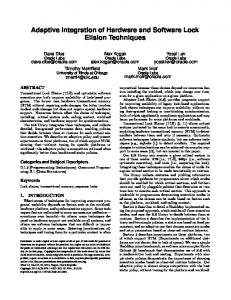
standards and this document”. Except for the SAS, there is no statement about a deviation process in DO-178B. In contrast, in DO-254, deviations from the approved plans should appear not only in the hardware accomplishment summary (HAS) but also in planning documents. Section 4.2, item 7 states: “The process for deviating from the established plans, if deviations become necessary and affect certification, should be identified.” In general, the PHAC is the most appropriate document to state how deviations from plans will be addressed. 6.4.4. Standards In DO-178B, software development standards, including software requirements standards (SRS), software design standards (SDS), and software code standards, should be defined for Levels A–C (Table A-1 of Annex A, item 5). In contrast, in DO-254, hardware design standards, including requirements standards, validation and verification standards, and hardware archive standards, may not be required but can become part of the certification basis if necessary, depending on the project (DO-178B Section 10.2). In particular, hardware archive standards to define the procedures, methods, and criteria to retain and archive product data in DO-254 are lifecycle data not included in DO178B. 6.4.5. Minimal data submission For DO-178B, lifecycle data that must be submitted to the certification authority include the Plan for the Software Aspect of Certification (PSAC), the Software Configuration Index (SCI), and the Software Accomplishment Summary (SAS). For DO-254, the Plan for the Hardware Aspect of Certification (PHAC), the Hardware Verification Plan (HVP), the Top-Level Drawing, and the Hardware Accomplishment Summary (HAS) should be submitted to the certification authority. Because the verification of the hardware system typically requires highly sophisticated and complex tests, the certification authority needs to ensure the feasibility of the verification plan. 6.5. Tool qualification Tools are used to eliminate, automate or replace the manual activities listed in DO-178B and DO-254. Prior to the use of a tool, tool assessment and qualification should be performed to ensure the capability of conducting the particular development (or design) or verification activities to an acceptable level of confidence [8]. Tools are classified as either development tools (or design tools), which can introduce errors into the product, or verification tools, which cannot cause errors but may fail to detect them. There are several major dissimilarities between the tool qualification in DO-178B and DO-254, as follows. Tools used under DO-178B need to be qualified under the three following conditions: (1) tools can introduce errors into the product or may allow errors to remain undetected; (2) processes may be eliminated, shortened, or automated; and (3) the output of the tool may not be verified independently. If any of these conditions is not applicable, no further tool qualification is required. The detailed flow chart of DO178B tool qualification is shown in Fig. 6. For DO-254, tool qualification activities vary depending on the type of tool, the design assurance level of the hardware functions, and other factors (e.g., relevant tool history). If the output of the tool is independently accessed, then no further tool qualification is required. If a Level D design tool (including lower levels) or Level C verification tool (including lower levels) is utilized, then no further tool assessment is need. If the applicant can provide evidence that the tool has been found to produce acceptable results and the previous tool usage is related to the proposed tool usage, then further tool qualification is not necessary. Unlike DO-254, the design assurance level and relevant tool history are not considered in DO-178B for determining tool qualification. Additionally, tool qualification is required for structural coverage tools if their outputs are not verified for DO-178B, whereas DO-254
Fig. 6. Flow diagram of tool qualification in DO-178B.
does not require qualification for elemental analysis (Section 11.4.1, item 4). The detailed flow chart of DO-254 tool qualification is shown in Fig. 7. 6.6. COTS (commercial-off-the-self) components DO-178B essentially requires COTS components to satisfy the objectives of DO-178B, and detailed guidance for usage of COTS components is not specifically addressed in DO-178B. However, DO-254 specifically addresses the usage of COTS components, even without detailed knowledge of the device design. For example, product service experience may be utilized to demonstrate design assurance for COTS components. Although COTS certification processes of DO-178B and DO-254 have different approaches, a plan to use COTS components and the means of compliance substantiation should be described in the PSAC and the PHAC for both DO-178B and DO-254, respectively. 7. Software and hardware as parts of the system Software can never be certified as a standalone entity, and certification authorities certify only complete aircraft, engines, and avionic systems, whereby all potential system interactions are available for inspection [17]. Thus, interactive and coordinated approaches for software/hardware certification processes should be considered at the system level. Fig. 8 shows the relationships between the various development documents, which provide guidelines for safety assessment, software and hardware life-cycle processes and the system development process. Within the system safety assessment process, an analysis of the system design defines safety-related requirements that specify the desired immunity from, and system responses to, failure conditions. These requirements are defined for software and hardware to preclude
896
W. Youn, B. Yi / Computer Standards & Interfaces 36 (2014) 889–898
Fig. 7. Flow diagram of tool qualification in DO-254 (Fig. 11-1 in DO-254).
the effect of failure and may provide fault detection and fault tolerance [7]. System functions may be allocated to one or more partitioned software/hardware components. As decisions are being made during the
software development processes and hardware design process, the system safety assessment process analyzes the complete system design to verify that it meets the safety requirements. The focus of information flow from the system process to the software/hardware process must
Fig. 8. Relationship between system development process and software and hardware development processes.
W. Youn, B. Yi / Computer Standards & Interfaces 36 (2014) 889–898
897
Table 5 DO-178B/DO-254 overview. Item
DO-178B
DO-254
Objectives Independence Design assurance Life cycle process and data
Specific according to level Well defined by objective Does not address FFP analysis Requirements, design, coding, integration process (manufacturing is not a concern)
Ambiguous Applicable for only levels A–B Allows FFP analysis Requirements capture, conceptual design, detailed design, implementation, production transition (requires acceptance testing) – Elemental analysis (and FFP) – Addresses validation of derived requirements – Robust testing: optional – PHAC – HAS Requirements, design, validation and verification, archive standards (optional) – PHAC – HVP – Top-level drawing – HAS – Depending on the type of tool, design assurance level of the hardware functions, and other factors (e.g., relevant tool history). – Allows a COTS approach without detailed knowledge of the device design
Development (design) process Verification and validation process Deviation process Standards Minimal data submission
Tool qualification COTS
– Structural coverage (MC/DC, DC, statement coverage) – Push validation to the system level – Robust testing: required – SAS Requirements, design and coding standards for levels A–C (required) – PSAC – SCI – SAS – Design assurance level and relevant tool history are not considered. – Essentially requires COTS to satisfy DO-178B
keep track of requirements allocated to software and hardware, particularly those requirements that contribute to system safety. A hardware development process exists parallel to the software development process and the flow of information between the software process and the system process [18]. The information below should be passed between the software and hardware life cycle processes. This information should flow via the system process. These data include [19]: • Derived requirements required for hardware/software integration, such as timing constraints, definitions of protocols, and addressing schemes for the interfaces between software and hardware; • Instances where software and hardware verification activities require coordination and enhancement; • Identified incompatibilities between the software and hardware, which may be part of a corrective action process. In addition, design trade-offs between software processes and hardware processes should also be considered at the system level for several reasons, such as achieving otherwise unattainable performance, achieving overall system reliability, and minimizing overall system costs. A software/hardware trade-off establishes the division of responsibility between software and hardware for performing system functions [20]. One of the most common reasons for trading software for hardware is to achieve performance that could not otherwise be obtained. In addition, software often is subject to failure due to frequent changes and inadvertent over-writing. Thus, there is a tendency of some applicants to move safety-critical functions to more secure locations in hardware to achieve overall system reliability. The boundary between software and hardware is usually drawn to minimize hardware costs or even the costs of the entire system, including software. Additionally, software design assurance levels may be improved by using protective software or hardware mechanisms elsewhere in the system. Such architectural methods include partitioning, the use of hardware or software monitors, and architectures with built-in redundancy. One characteristic of hardware/software trade-offs is that they must be carefully repeated each time a new system is developed. In fact, software/hardware trade-offs appear at the heart of the design process; therefore, they must always be reevaluated in terms of design goals and constraints, as well as the limits of contemporary technology. Appropriately designing trade-offs between software processes and hardware processes effectively facilitates the certification process required by these standards, minimizes the overall cost, and ultimately ensures the safety of the entire avionic system.
Depending on the characteristics of the system and the development process used, the testing of software and hardware integration may occur on breadboards, in prototypes, in labs, during computer emulation, or in flight-worthy articles [19]. The output is equipment under formal configuration control, together with the development assurance data and software and/or hardware life cycle data. Detailed procedures during the design-build process should be used to verify that all software and hardware integration requirements are satisfied. It may be helpful to enhance the software/hardware integration process through the development of interface documents. This would ensure that the hardware and software provide compatible functionality. Potential problems during the integration of software and hardware components might include interface protocol errors, data communication errors, and compatibility errors. The identified problems should be automatically tracked back to the appropriate development or integral processes (e.g., requirements capture, allocation or validation; implementation; verification) to address the underlying root cause to ensure that similar problems do not recur in the future, and the process should be iterated. When all the iterations are completed, the output of this process is a verified integrated system, along with data demonstrating that the system meets all functional and safety requirements. 8. Summary The goal of the paper is to present a comprehensive comparison between various aspects of avionic software and hardware standards. Software/hardware assurance begins at the system level with the allocation of system functions to software/hardware, respectively, and the assignments of their corresponding system development levels [8]. A single system function can be assigned to a software item, to a hardware component or to a combination of software and hardware. The software and hardware domains mutually affect each other in developing the avionic system, and the failure or malfunction of the software can be often attributable to interaction with a hardware component. Thus, harmonized and coordinated interaction between software development and the hardware design process are crucial issues, and software and hardware components should be planned, developed and certified in a unified manner to ensure the safety of avionic systems [4]. Over the past decades, both DO-178B and DO-254 guidelines have served the avionics industry well and have ensured the safety required by highly safety-critical avionic systems. However, the ambiguity and flexibility of the guidelines result in various interpretations and implementations by different applicants; high costs in software development
898
W. Youn, B. Yi / Computer Standards & Interfaces 36 (2014) 889–898
and hardware design are often attributable to insufficient understanding and misinterpretation of these standards [9]. Once the development of a software/hardware product has been completed, it cannot be reversed to include the standard, which might increase the development cost dramatically [21]. Therefore, it is important to understand the similarities and differences between DO-178B and DO-254 to reduce potential compliance problems, minimize development costs, and ultimately assure the integral safety of avionic systems. To the best of our knowledge, there have been a few studies that have investigated DO-178B and other standards [11,22,23], but very few studies have made comprehensive comparisons between DO178B and DO-254. This study reviewed and summarized DO-178B and DO-254 in terms of diverse perspectives, including objectives, independence, design assurance, life cycle processes and data, tool qualification, and COTS. Moreover, an overview of the software and hardware general characteristics is presented in this paper. Therefore, this study has significant implications in terms of demonstrating the overview and the similarities and differences between DO-178B and DO-254; it may assist practitioners in understanding the rationales behind the two main standards used in avionic industries (Table 5). Acknowledgments This research was supported by the Happy Tech. program through the National Research Foundation of Korea (NRF) funded by the Korean Ministry of Education, Science and Technology (No. 2012-0020449). References [1] A. Kornecki, J. Zalewski, Software certification for safety-critical systems: a status report, IEEE, 2008, pp. 665–672. [2] P. Rodríguez-Dapena, Software safety certification: a multidomain problem, IEEE Softw. 16 (1999) 31–38.
[3] I. Dodd, I. Habli, Safety certification of airborne software: an empirical study, Reliab. Eng. Syst. Saf. 98 (2012) 7–23. [4] A. Kornecki, B. Butka, J. Zalewski, Software tools for safety-critical systems according to DO-254, Computer 41 (2008) 112–115. [5] F. Yan, J. Yang, P. Wang, Study of safety design of avionics software in civil aviation, IEEE, 2010, pp. 425–429. [6] C. Bertrand, C.P. Fuhrman, Towards defining software development processes in DO-178B with openup, IEEE, 2008, pp. 000851–000854. [7] Software Considerations in Airborne Systems and Equipment Certification, 1992. [8] Design Assurance Guidance for Airborne Electronic Hardware, 2000. [9] W.E. Wong, A. Demel, V. Debroy, M.F. Siok, Safe software: does it cost more to develop? IEEE, 2011, pp. 198–207. [10] A.J. Kornecki, J. Zalewski, Hardware certification for real-time safety-critical systems: state of the art, Annu. Rev. Control 34 (2010) 163–174. [11] H. Hesselink, A comparison of standards for software engineering based on DO-178B for certification of avionics systems, Microprocess. Microsyst. 19 (1995) 559–563. [12] F. Yan, Comparison of means of compliance for onboard software certification, IEEE, 2009, pp. 917–920. [13] R. Patton, S.T.B. Online, S.B. Online, Software Testing, Sams, 2001. [14] R.W. Butler, G.B. Finelli, The infeasibility of quantifying the reliability of life-critical real-time software, IEEE Trans. Softw. Eng. 19 (1993) 3–12. [15] R.S. Pressman, W.S. Jawadekar, Software Engineering-A, Tata McGraw Hill Publication Tata McGraw Hill Publication, 1982, p. 4. [16] B.M. Brosgol, Safety and security: certification issues and technologies, Crosstalk, J. Def. Softw. Eng. 21 (2008) 10. [17] J. Rushby, New challenges in certification for aircraft software, Proceedings of the Ninth ACM International Conference on Embedded Software, ACM, 2011, pp. 211–218. [18] T.K. Ferrell, U.D. Ferrell, RTCA DO-178B/EUROCAE ED-12B, 2000. [19] S. international, ARP (aerospace recommended practice) 4754A, Guidelines for Development of Civil Aircraft and Systems, 2010. [20] R.L. Mandell, Hardware/software trade-offs: reasons and directions, Proceedings of the December 5–7, 1972, Fall Joint Computer Conference, Part I, ACM, 1972, pp. 453–459. [21] V. Hilderman, T. Baghi, Avionics Certification: A Complete Guide to DO-178 (Software), DO-254 (Hardware), Avionics Communications, 2007. [22] W.R. Bush, Software, regulation, and domain specificity, Inf. Softw. Technol. 49 (2007) 44–54. [23] K.B. Codur, A.H. Dogru, Regulations and software evolution: an example from the military domain, Sci. Comput. Program. 77 (2011) 636–643.