STATISTICAL CLUSTERING APPLIED TO ADAPTIVE MATCHED FIELD PROCESSING Brian Tracey, Nigel Lee, and Srinivas Turaga MIT Lincoln Laboratory 244 Wood St. Lexington, MA 02420
[email protected],
[email protected] ABSTRACT Cluster analysis provides a tool for mapping out regions of ambiguous response in sparse array beamforming problems. This paper discusses clustering and its application to matched field processing (MFP) problems in ocean acoustics. The map of the ambiguity volume provided by clustering can be used for improved interpretation and postprocessing. By peak-picking in cluster space, rather than in spatial dimensions, we are able to identify and discard spatial peaks that result from the presence of a strong source. As shown in a data example, clustering can help collapse 3-D MFP output to bearings-only while preserving signal gains obtained by accounting for multipath. Clustering can also provide computational gains by allowing elimination of highly redundant replicas. 1. OVERVIEW OF MATCHED FIELD Matched field processing has been extensively explored for use in detecting and localizing underwater sources. MFP uses ocean propagation models to account for multipath when generating replica vectors. If accurate environmental information is available, sources can be localized in range, depth, and bearing. Accurately modeling multipath can also yield mismatch reduction and detection gains as compared to direct-path beamformers. A significant problem for MFP is that the beamformer output often displays high ambiguities in range and depth, with a single source leading to multiple spatial peaks. This is particularly true for arrays without significant vertical aperture because of their limited ability to resolve multipath. MFP for these arrays can be thought of as a form of sparse array processing with resultant high ambiguities. Many of the ambiguous peaks may be within a few dB of the overall peak, so they are not easily suppressed with adaptive beamforming. This work was sponsored by DARPA-ATO under Air Force Contract F19628-00-C-0002. Opinions, interpretations, conclusions, and recommendations are those of the authors and are not necessarily endorsed by the United States Government.
MFP replicas are generated for a set of look directions in range, depth, and azimuth. If we define Θ = (r, φ, z) as the look direction, the MFP output for an N element array at frequency f0 , time t0 , and direction Θ is given by 2 P (f0 , t0 , Θ) = wH (f0 , t0 , Θ)x(f0 , t0 )
(1)
where w(f0 , t0 , Θ) is the N × 1 adaptive weight vector and xH (f0 , t0 ) is the current data snapshot. Applying the adaptive weights to individual snapshots, rather than to a covariance matrix, helps reduce smearing due to target motion. The adaptive weight is based on the corresponding replica vector v(f0 , t0 , Θ) and the N × N sample covariance matrix. The replica vectors are calculated using an appropriate propagation model [5]; an adiabatic normal modes approach is used here. The sample covariance matrix is computed using a time average of FFT snapshots. In passive sonar the covariance matrix contains data from the target as well as interferers, so signal mismatch and self-nulling can be significant problems. In this paper we will apply the dominant mode rejection algorithm with white noise gain control (DMR-WNGC) for adaptive processing [2]. This algorithm approximates the sample covariance matrix as the sum of a dominant eigenvector subspace and a noise subspace. Protection against mismatch is provided by adding a diagonal load that varies with look direction to satisfy a white noise gain constraint. 2. CLUSTERING CONCEPTS AND APPROACHES Statistical clustering methods [3] enable identification of regions of similar response on the ambiguity surface. Clustering algorithms require a distance measure to estimate the similarity between two given vectors. For our problem, a natural distance measure is given by the cosine between two replicas [1]. The distance between two frequency domain replica vectors vi and vj is given by: dist(vi , vj ) , 1 −
H
v · v j 2 i
kvi k2 kvj k2
.
(2)
This distance metric is then used to determine which vectors should be clustered together. Clustering has been previously applied to sparse array direction-finding problems [4] using the same distance metric. Algorithms used to perform clustering have two main outputs. The first is a set of cluster centers, each of which is a single replica vector that is chosen to be representative of all members of its cluster. As shown in Figure 1, the cluster center can be considered to be equivalent to the axis of main response (MRA) for a standard beampattern. The second output is a cluster map listing all of the replicas which belong to the cluster represented by each center. These points correspond to main lobe look directions. For the methods used here, the user must specify a cluster radius, or maximum allowable mismatch between each cluster center and all cluster members. This radius is equivalent to the “dB down” number typically used to define main lobe width. The utility of clustering is indicated by the sparse array beampattern shown in Figure 1. When grating lobes are present, look directions that are within the specified cluster radius may be spatially distributed over a wide region. Clustering provides an automated way to identify these distributed regions of similar response.
Cluster center Cluster members
Power, dB
Cluster radius
Steering angle
Figure 1: Beampatterns for nominal well-sampled (solid line) vs. sparse arrays (dashed line). Commonly used clustering algorithms such as k-means or heirarchical clustering are extremely slow when applied to large-dimensional problems such as MFP. We have found that the following ideas help significantly for the MFP clustering problem: • the clustering method should be “greedy,” meaning that it does not seek the optimal clustering solution; • a divide-and-conquer (denoted DnC) approach should be used, in which the method operates on sub-sets of replica vectors to build up the solution;
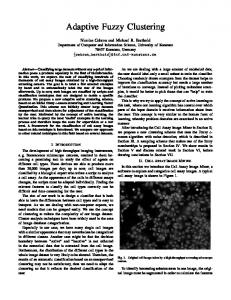
• if the array geometry and environment vary smoothly with time, techniques for quickly updating previous cluster results can be employed. In test cases, using a greedy algorithm gave a speedup of roughly 1000×. Combining the DnC idea with a greedy algorithm gave another 10-20× speedup, while fast updating techniques gave an additional speedup of 3-5×. 3. CLUSTER ANALYSIS OF MFP REPLICAS In this section we will use cluster analysis to gain insight into the 3-D structure of the MFP array manifold. MFP simulations were carried out using environmental parameters from the Santa Barbara Channel (SBCX) experiment [7]. Simulations were done comparing a notional single-line array (101 phones at 2 m spacing) to a volumetric array consisting of three vertically stacked arrays with 30 m total vertical aperture. Simulations were done for frequencies and source levels used in the actual SBCX test (12 tones from 64-338 Hz at 159 dB re 1 µPa ) with 80 dB white noise added. Figure 2 shows how the members of an example cluster at 94 Hz are distributed in three dimensions. Clusters were generated with 1.5 dB cluster radii for the single-line array described above. Cluster members are well grouped in bearing but are widely distributed in range and depth. While not shown here, similar patterns are seen when plane-wave replicas are used as cluster centers for clustering the MFP replicas. When vertical aperture is added the cluster members become more clumped in range and depth. This plot demonstrates several important features: • When vertical aperture is limited, source azimuth is much better resolved than range or depth. Thus the SNR and environmental calibration requirements for correctly localizing source bearing will be much lower than for range / depth localization. • While cluster members for the single-line array are widely scattered across range and depth, several clusters will be required to fully sample the search space along a particular bearing. To further explore the properties of MFP clusters we consider an endfire search problem for the single-line array. The array’s sensitivity to multipath is highest at endfire, so the potential benefit of accounting for multipath propagation is greatest in this region. As a proposed search, we consider a volume extending from -30 to +30◦ around forward endfire, over the full water depth of 0-210 m, and from 1-10 km in range. The space is gridded with 15 azimuthal beams and is sampled every 10 m in depth and every 50 m in range.
wave and clustered MFP replicas, allowing 1.5 dB mismatch. The plane-wave replica set coverage drops from roughly 70% to 20% as frequency increases. When clustered MFP replicas are used, better than 90% coverage is achieved. Figure 4 compares the number of replicas used for unclustered vs. clustered MFP. The number of clusters grows with frequency as array resolution improves, but a reduction of roughly two orders of magnitude is seen. Thus the clustered replica set achieves increased coverage by including multipath but requires many fewer replicas than standard MFP. 6
10
We define a coverage metric for comparing the use of direct-path and clustered MFP replicas. Coverage is defined as the fraction of the search volume vs for which the mismatch, minimized over the set of replica vectors vθ , is below some threshold γ for allowable mismatch: min dist(vs , vθ ) < γ.
(3)
θ
High coverage at a low γ indicates that aggressive adaptation is possible without significant target self-nulling. To add realism, environmental mismatch is introduced into the MFP replicas; the starting compressional soundspeed in the seabed has been lowered from 1628 to 1600 m/s, and sound speed profile points in the water column have been perturbed randomly by ±1 m/s. This environmental mismatch gives roughly 1 dB beamformer mismatch across much of the search space. 100 Clusters
90 80
% Coverage
70 60 50
Planewave
40 30 20 10
100
150 200 250 Frequency, Hz
300
Figure 3: Percent coverage for endfire search volume, allowing for a maximum mismatch of γ = 1.5 dB. Figure 3 compares coverage values calculated for plane-
Number of replicas
Figure 2: Three-dimensional view of example cluster for single-line array, 94 Hz simulation.
MFP
5
10
4
10
1.5 dB clusters
3
10
2
10 50
100
150
200
250
Frequency, Hz
300
350
Figure 4: Number of replicas required for endfire search.
4. COMPUTATIONAL GAINS As shown above, a significant reduction in the number of steering vectors can be achieved by replacing the MFP replicas with the set of cluster centers. Beamformer output in 3-D can be recovered by mapping the output power for each cluster center to all cells belonging to the cluster. This approach achieves computational savings proportional to the reduction in the number of replicas. The cost of this computational gain is a potential squint loss equal to the cluster radius. Thus the acceptable squint loss can be a useful criterion for choosing cluster size. For the three-line array simulations described above, a cluster radius of 1.5 dB did not introduce significant squint loss in reconstructed 3-D output. A smaller cluster radius (roughly 0.5 dB) was required to reconstruct single-line results with the same degree of accuracy. Squint loss can be reduced by using ’multi-level’ clustering. In this concept, a relatively coarse clustering can be used for an initial gridding of space. If high output SNR is seen for a particular cluster (indicating that the cluster contains a source), that cluster can be rebeamformed using either the actual MFP replicas or a set of smaller clusters generated with a smaller radius. The actual computational gain depends on the problem considered. For the SWellEx data example shown below
(which is a static array geometry) an overall speedup of roughly 17× was observed. When the array shape deforms over time it is necessary to re-generate and re-cluster the replicas. In these cases clustering can often reduce the adaptive weight calculation time by an order of magnitude, though the overall speedup may be limited to 3-4× due to the need to frequently recalculate the replicas. 5. BEARINGS-ONLY CLUSTER LOCALIZATION Figure 2 above showed that horizontal arrays typically have poor ability to estimate range and depth but good ability to estimate bearing. The results also showed that along a given bearing, a single replica (whether derived from direct-path or clustered MFP replicas) did not provide complete coverage. Motivated by these observations, we will explore the use of clusters for bearings-only localization. The extra information provided by clustering can aid in collapsing three-dimensional search results to bearings-only, giving gains in track SNR and deflection ratio. In general, multiple clusters will be centered on each azimuth. The most straightforward way to collapse them is by a simple ’max’ operation for all clusters centered on each azimuth. Similarly, standard MFP results can be collapsed by maximizing along range and depth. These maximizations will preserve any signal gain achieved from accurately modeling multipath. They will also increase the displayed noise level, an effect often referred to as ORing loss. The ambiguity surface map provided by clustering gives information that can be used to reduce ORing loss. One way to separate sources from noise is to search for clusters that are peaks in their local neighborhood. Mathematically, we seek clusters whose output power Pi satisfies Pi > P j
∀j ∈ Ni
(4)
where Ni is the set of cluster centers j in the neighborhood of the cluster i. While noise will occasionally give local peaks in output power, the majority of noise outputs will not. Collapsing to bearing by ORing over the peak clusters on each bearing should therefore give an improvement in displayed signal-to-noise ratio. The local neighborhood can be defined as the set of all clusters whose centers are mismatched from the current cluster center by less than some threshold: i j dist(vcen , vcen )≤η (5) Setting the threshold η to be twice the radius of the individual clusters is a reasonable choice. Several modifications to this definition were found to be helpful. A criterion can be imposed that the difference in bearing between the test cluster center and its neighbors should not exceed 1-2 beams. It can also be helpful to avoid rejecting nearby clusters that have output power very close to that of the local peak. These
modifications help avoid rejection of a quieter source near a loud source. This type of peak-picking operation clearly does not represent an optimal solution to the problem of detecting a signal in cluster output. The goal of the current work is simply to indicate that cluster outputs can be reduced to a bearingsonly display while retaining measurable gains over a directpath beamformer. Bearings-only cluster localization has been applied to data collected as part of the SWellEx-96 ocean acoustics experiment (www.mpl.ucsd.edu/swellex96). For data analysis we concentrate on event S5, in which the towship R/V Sproul towed a pair of sources which each projected a comb sequence of tones. Results are shown for the bottom-mounted HLA North array, an irregularly-spaced array of roughly 240 m overall length. During the time period analyzed, the towed source was in the aft endfire (south) direction from the array and was moving from roughly 2 to 4.5 km in range. Figure 5 shows a bearing-time record (BTR) for adaptive processing of a projected 235 Hz tone using rangefocused replicas. The result was constructed by using five range-focused replica vectors with focus ranges uniformly spaced between 2-10 km. This represents an oversampling in range and was done to minimize the potential mismatch (though the range-focusing had little effect near endfire, as expected). The DMR beamformer used 15 snapshots to estimate 5 degrees of freedom, with a 6 dB white noise gain constraint applied. While the high SNR towed source is clearly visible, some time periods of high adaptive selfnulling are seen along the track. At these time periods the signal model mismatch is high enough that the adaptive processor partially cancels the signal of interest. Figure 6 shows cluster beamformer output where the two-stage (peak-pick, then OR) method outlined above has been applied. In this case peak-picking was only allowed within ±2 azimuthal beams of each cluster center. The same adaptive beamforming parameters were used as in the range-focused case. The cluster result shows additional power on source tracks, due to mismatch reduction, and a noise floor similar to that seen in the range-focused result. The result is a display which has increased SNR on the projected tone and provides clearer tracks for several other traces. The track detectability can be measured using the deflection ratio, defined as the difference in expected values of signal and noise, normalized by the standard deviation of the noise: √
d=
E{P | H1 } − E{P | H0 } . σ{P | H0 }
(6)
This quantity was calculated along the track of the towed source for the cases above. The expectation was calculated over 5 snapshots centered on the current time with a split window in bearing. The track beam and three guard
32
75
34
70
36
65
38
60
40
55
42 44
50
46
45
48
10
20 30 Azimuth, beam
40
40
Figure 5: SWellEx-96 bearing-time record (BTR), 235 Hz projected tone, for time period with R/V Sproul in aft endfire. Azimuthal beams are cosine-spaced from −60o to 60o . Results are shown for range-focused replicas. The towed source is near endfire, in beams 22-25.
0.3
Probability distribution
80
Power, dB
Time, minutes
30
beams on either side were excluded from the noise calculation, with noise estimated from a five-beam window on either side. To allow for track jitter, the deflection ratio was maximized over the track beam and one beam on either side. Figure 7 shows the distributions of along-track deflection ratios for the BTR displays above. Deflection is also shown for a BTR of MFP results collapsed along range and depth (not shown here). Because the MFP and clustered results avoid significant self-nulling, the probability of low deflection is reduced for these beamformers. The collapsed MFP result shows an increase in overall deflection of only 1 dB because the increase in signal level is offset by an increase in displayed noise due to ORing loss. The clustered result, which preserves the signal gains of MFP but avoids large increases in displayed noise, shows an increase of roughly 4 dB in median deflection ratio.
0.2
0.1
80
32
75
34
70
36
65
38
60
40
55
42 44
50
46
45
48
10
20 30 Azimuth, beam
40
10
20 30 Deflection ratio, dB
40
Figure 7: Estimated probability distributions for deflection ratio along source track, 235 Hz tone example above.
Power, dB
Time, minutes
0 0
30
Clusters Direct path MFP
40
Figure 6: Cluster-based bearing-time record (BTR) for the event S5 example above. Note the increased SNR on the towed source as well as the improved definition of the weaker track near beam 16.
6. USE OF CLUSTERS IN POST-PROCESSING FOR 3-D LOCALIZATION A final application of clusters is in identifying and rejecting ambiguous peaks in 3-D beamformer output. Ideally these ambiguities would be suppressed by adaptive processing. However, the need to scale back adaptivity to reduce sensitivity to mismatch, combined with the inherent high sidelobes associated with MFP, means that significant ambiguities generally remain in beamformer output. The cluster map derived from MFP replica vectors gives a way of representing the correlations between different beamformer steering vectors. By knowing how the cluster centers are related, we can predict that a source in cluster A will also excite nearby clusters B and C at some lower level. If in the data we observe that cluster A is more strongly excited than B or C, we can conclude that the second two clusters are measuring sidelobe energy that should be discarded. The
30 20
Time, epochs
40
20
60 15 80 10
100
Normalized power, dB
25
5
120 2
4
6 Range, km
8
10
0
Figure 8: Simulated normalized AMFP results, single-line HLA, 166 Hz tone.
7. SUMMARY Applying matched field processing concepts to sonar arrays with limited aperture often results in a set of highly overlapped replica vectors. Clustering methods can be used to identify and map out the resulting ambiguities in the array manifold. Ways of exploiting the cluster map have been described above. As demonstrated using SWellEx-96 HLA data, bearings-only clustering can show mismatch reduction benefits in comparison to direct-path beamforming.
30 20
20
60 15 80 10
100
Normalized power, dB
25
40 Time, epochs
mask generated by the peak-picking operation can then be used to zero out beamformer output for non-peak locations. This mask is applied to the SNR estimate generated using a spatial normalization algorithm. A similar approach has been taken in applying the CLEAN algorithm to adaptive matched field results [6]. One advantage of the cluster peak-picking is that it does not assume the highest peak to be the true source location, which may be helpful in low SNR situations when noise may elevate a sidelobe to be the global maximum. Figure 8 shows simulated adaptive MFP output for a 166 Hz tone projected from the source described above, received on the single-line HLA array. Beamformer output is shown at the source bearing (endfire) and depth (50 m), and is normalized by a noise floor estimated from the 25th percentile of all beams. With no peak-picking, significant range ambiguities are seen parallel to the source track. These ambiguities are reduced using cluster-based peak-picking. If a small cluster radius is used, as in Figure 9, the rejection of ambiguities is excellent. However, SNR and environmental mismatch may require that a larger cluster size be chosen. Simulation examples have shown that noticeable cleanup is also obtained for a cluster radius of 1.5 dB.
5
120 2
4
6 Range, km
8
10
0
Figure 9: Simulated results for cluster peak-picking with 0.3 dB radius, single-line HLA, 166 Hz tone. 8. REFERENCES [1] H. Cox. Resolving power and sensitivity to mismatch of optimum processors. J. of the Acoustical Society of America, 54(3):771–785, 1973. [2] H. Cox and R. Pitre. Robust DMR and multi-rate adaptive beamforming. In 1997 31st Asilomar Conference, pages 920–924, 1997. [3] B. S. Everitt. Cluster Analysis. John Wiley & Sons, New York, 1993. [4] K. Forsythe. Clustering of direction-finding estimates at HF (U). Technical Report AST-26, MIT Lincoln Laboratory, May 1994. [5] F. Jensen, W. Kuperman, M. Porter, and H. Schmidt. Computational Ocean Acoustics. American Institute of Physics, New York, 1993. [6] H. Song, J. de Rosny, and W. Kuperman. Improvement in matched field processing using the CLEAN algorithm. J. of the Acoustical Society of America, 113(3):1379–1386, March 2003. [7] L. Zurk, N. Lee, and J. Ward. Source motion mitigation for adaptive matched field processing. J. of the Acoustical Society of America, 113(5):2719–2731, May 2003.