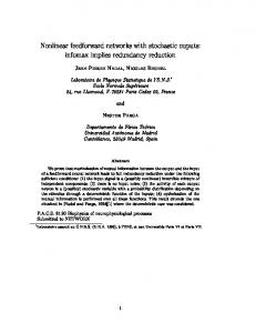
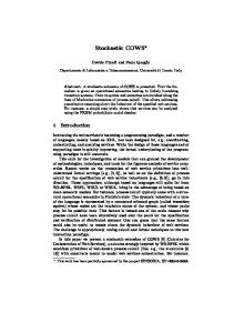
Stochastic TDC Architecture with Self-Calibration Satoshi Ito, Shigeyuki Nishimura, Haruo Kobayashi, Satoshi Uemori, Yohei Tan Nobukazu Takai, Takahiro J. Yamaguchi, Kiichi Niitsu Dept. of Electronic Engineering, Gunma University, Kiryu Gunma 376-8515 Japan
Abstract— This paper describes a time-to-digital converter (TDC) architecture with fine time resolution, self-calibration and self-testing, and these features are realized by the following: (1) Encoder circuit that ensures monotonic characteristics. (2) Self-calibration circuit for linearity improvement. (3) Stochastic architecture for fine time resolution. (4) Self-testing for reliability requirements. These features can be implemented with an advanced fine CMOS process using digital design methodology. The circuit structure and operation are described, and MATLAB simulation results are presented. Keywords: TDC, Stochastic TDC, Self-Calibration, Self-Testing
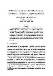
I. I NTRODUCTION A Time-to-Digital-Converter (TDC) measures the time interval between two edges, and time resolution of several picoseconds can be achieved when the TDC is implemented with an advanced CMOS process. TDC applications include phase comparators of all-digital PLLs, sensor interface circuits, modulation circuits, demodulation circuits, as well as TDC-based ADCs [1]-[12]. The TDC will play an increasingly important role in the nano-CMOS era, because it is well suited to implemention with fine digital CMOS processes; a TDC consists mostly of digital circuitry, and resolution improves as switching speed increases. This paper reports on a new TDC architecture suitable for implementation with fine digital CMOS; it achieves fine time resolution and high linearity, and has self-calibration and selftesting features. II. C ONVENTIONAL TDC A RCHITECTURE Basic TDC: Fig.1 shows the configuration of a basic TDC: the reference CLK passes through a buffer delay line, which consists of a chain of inverters, and the delayed reference CLK signals are used as the data input for some flip-flop (DFF) circuits. The measured signal is used as the clock signal of the flip-flops. We obtain the outputs of the flip-flops as a thermometer code, according to the rise-edge-timing interval between the reference“START” edge and the ”STOP” edge, and the encoder transforms it into a binary code. The time resolution is determined by the gate delay 𝜏 . Vernier Delay Line TDC : Fig.2 shows a vernier delay line TDC which uses two delay lines: one, with a buffer delay of 𝜏1 , for the reference edge, and the other, with a buffer delay of 𝜏2 , for the edge under measurement. Time resolution is given by 𝜏1 − 𝜏2 (gate delay difference) which can be smaller than that of the basic TDC, but note that it uses 2N buffers (N buffers of 𝜏1 and N buffers of 𝜏2 ) for an input range from 0 to N (𝜏1 − 𝜏2 ).
978-1-4244-7456-4/10/$26.00 ©2010 IEEE
email: k
[email protected]
Problems of Conventional TDCs : The vernier delay line TDC can have fine time resolution, but its monotonicity is not guaranteed. Both the basic and vernier delay line TDCs may show some nonlinearity due to buffer delay mismatches. III. P ROPOSED TDC A RCHITECTURE A. Encoder Circuit Our TDC architecture is based on the basic TDC architecture (Fig.1), which is similar to a flash ADC. The outputs of DFFs may have so-called bubble errors due to setup and hold time mismatches among DFFs [8]. We use an encoder circuit, which counts the number of ”1” outputs from the DFFs, to ensure monotonicity of the TDC, and we have designed the encoder using an array of full adders (Fig.3). B. Self-Calibration The basic TDC in Fig.1 may show nonlinearity characteristics due to delay-time mismatches among delay buffers; the proposed TDC has self-calibration circuits to compensate for this nonlinearity Our TDC uses a two-ring-oscillator configuration in the self-calibration mode, as shown in Figs. 4 and 5. Since the oscillation frequencies of the two oscillators are different from each other and not synchronized, the histograms in all bins would be equal, after collection of a sufficiently large number of data, if the TDC had perfect linearity [9], [10]. We performed MATLAB simulation to confirm that the above statement is valid for the basic TDC architecture (Fig.6). (However, we found from simulation that it is not valid for the vernier-type TDC architecture.) In reality there is nonlinearity (due to factors such as buffer-delay mismatches) and the histogram in each bin fluctuates being proportional to DNL: this is analogous to an ADC histogram test with a precise ramp input (which is difficult to generate on-chip), however in the TDC test case just a ring-oscillator configuration is sufficient because the signal is “time” instead of “voltage”. Fig.7 explains the principle of the self-calibration. ∙ In self-calibration mode, the histogram engine collects histogram data as DNL values, and obtains INL by accumulating the DNL values. Then it calculates the inverse function of the INL values and stores them in memory. ∙ In normal operation mode, the encoder output is corrected by the inverse function of the INL values in memory, to obtain linear TDC input-output characteristics. The above self-calibration can be done using all-digital methods, and Fig.8 shows simulation results.
1027
We note that the above self-calibration is to compensate for the buffer delay relative mismatches and obtain high linearity, and the calibration of the absolute average delay of the buffers can be done using a delay-locked loop [11]. C. Stochastic TDC Structure Next we consider to utilize the large variation in circuit characteristics of fine CMOS to obtain fine time resolution. We connect each delay buffer output to the data inputs of several DFFs (Fig.9, [12]). Since setup and hold times of the DFFs are not identical due to process variations, the edge timing which changes DFF output from 0 to 1 can be different among these DFFs. Then their statistical variation becomes the effective time resolution of the TDC, which is generally finer than the buffer delay 𝜏 . This stochastic TDC may be highly nonlinear, but its nonlinearity can be compensated by the above self-calibration method; in other words, the self-calibration makes the stochastic architecture practical for realizing a linear TDC with fine (sub-pico second) time-resolution. Also note that since the stochastic TDC utilizes the variation in characteristics positively, each MOSFET in DFFs and delay line buffers can be implemented with minimum channel length and width, which reduces power consumption and is advantageous in a high-switching-speed fine CMOS process. D. Self-Testing Function
R EFERENCES [1] J. Yu, et. al., , “A 12bit Vernia Ring Time-to-Digital Converter in 0.13𝜇m Technology”, IEEE JSSC, vol. 45, no. 4 (April 2010). [2] M. Zanuso, et.al., “Time-to-Digital Converter for Frequency Synthesis Based on a Digital Bang-Bang PLL”, IEEE Trans. CAS, (March 2010). [3] S. Henzler, et. al., “90nm 4.7ps-Resolution 0.7-LSB Single-Shot Precision and 19pJ-per-Shot Local Passive Interpolation Time-to-Digital Converter with On-Chip Characterization”, ISSCC (Feb. 2008). [4] R. B. Staszewski, et.al., “1.3V 20p Time-to-Digital Converter for Frequency Synthesis in 90-nm CMOS”, IEEE Trans. CAS II (Mar.2006). [5] M. Lee, A. A. Abidi, “A 9b,1.25ps Resolution Coarse-Fine Time-toDigital Converter in 90nm CMOS that Amplifies a Time Residue”, Symposium on VLSI Circuits (June 2007). [6] C. Hsu, et.al., “A Low-Noise,Wide-BW 3.6GHz Digital ΔΣ Fractional-N Frequency Synthesizer with a Noise-Shaping Time-to-Digital Converter and Quantization Noise Cancellation,” ISSCC (Feb. 2008). [7] T. Komuro, et.al., “ADC Architecture Using Time-to-Digital Converter”, IEICE vol. J90-C (April 2007). [8] B. Razavi, Principle of Data Converter System Design, IEEE Press (1995). [9] J. Rivoir, ”Fully-Digital Time-to-Digital Converter for ATE with Autonomous Calibration,” IEEE International Test Conference (Oct. 2006). [10] J. Rivoir, ”Statistical Linearity Calibration of Time-to-Digital Converters Using a Free-Running Ring Oscillator,” 15th Asian Test Conference, pp.45-50 (Nov. 2006). [11] I. Mori, et. al., ”High-Resolution DPWM Generator for Digitally Controlled DC-DC Converters”, IEEE Asia Pacific Conference on Circuits and Systems (Dec. 2008). [12] V. Kratyuk, et. al., “A Digital PLL with a Stochastic Time-to-Digital Converter,” IEEE Trans. CAS I, (August 2009) . [13] ISSCC Short Course, Automotive Technology and Circuits, San Francisco (Feb. 2005). [14] H. Casier, P. Moern, K. Appeltans, “Technology Consideration for Automotive,” Proc. of ESSCIRC, pp.37-41, Leuven, Belgium (Sept. 2004).
A self-testing function is often required in automotive applications [13], [14], and here we consider how to incorporate it in the proposed TDC. The following self-testing configuration and operation check whether DFFs have some faults (Fig.10). In self-testing mode, the DFF arrays are configured as Johnson counters (or ring counters, linear feedback shift registers), and all flip-flops are reset. Also the clock for the DFFs is generated by the ring oscillator. Then the Johnson counters operate and their outputs are compared using digital comparators (EXORs) with the expected value stored in the memory. If an output disagrees with the expected value, then the corresponding set-reset FF is set to 1. After some clock periods, the diagnostic output is read, and if it is ”1” we know that there are some faults in DFFs. IV. C ONCLUSIONS We have proposed a TDC architecture with fine time resolution, high linearity, self-calibration and self-testing. We described circuit structure and operation, and presented MATLAB simulation results. We conclude this paper by noting that the proposed TDC can use completely digital methods for design, verification, self-calibration, testing, layout (hence even FPGA implementation is possible), and receives more advantages with fine digital CMOS implementation.
Fig. 1.
Basic TDC architecture and operation.
Fig. 2.
ACKNOWLEDGMENT
We acknowledge H. Miyashita, K. Rikino, S. Kishigami, Y. Yano, T. Gake, T. Mori, O. Kobayashi, T. Matsuura, S. Arai, T. Komuro, K. Wilkinson and STARC.
1028
A vernier delay line TDC.
(a)
Fig. 4.
Proposed TDC architecture with self-calibration.
(b)
(c)
(a)
(d) Fig. 3. Encoder circuit to compensate for bubble error. (a) TDC with encoder to compensate for bubble error. (b) Thermometer code and bubble error. (c) Encoder which counts number of 1’s from DFF outputs. (d) Simple encoder design example with full adders.
(b) Fig. 5. Operation of the the proposed TDC architecture with self-calibration. (a) Self-calibration mode. (b) Normal operation mode.
1029
Fig. 6. Simulation result of histograms in self-calibration mode. Ideally linear TDC case (left). Nonlinear case (right).
(a)
(b) Fig. 9. (a) Stochastic TDC architecture. Timing offset of each DFF is assumed to be random. (b) Coarse time resolution of the conventional TDC (left). Fine time resolution of the stochastic TDC (right).
Fig. 7.
Principle of the self-calibration.
(a)
Fig. 8. Simulation result of the self-calibration. Histogram before calibration (left). Histogram after calibration (right).
(b) Fig. 10. Self-testing function. (a) First, all flip-flops are reset at start. (b) Next, Johnson counter configuration starts self-testing.
1030