CHAOTIC SYSTEMS SYNCHRONIZATION IN SECURE COMMUNICATION SYSTEMS Ahmad M. Harb Electrical Engineering Dept. Jordan Univ. of Science and Technology Irbid, Jordan
[email protected]
Wajdi M. Ahmad Electrical and Computer Engineering Dept. University of Sharjah Sharjah, UAE
[email protected]
ABSTRACT
In this paper, synchronization of two chaotic signals is studied and analyzed. A nonlinear recursive backstepping scheme is utilized to design an appropriate control input signal that achieves synchronization between the two chaotic signals. For the sake of comparison, an alternative master-slave synchronizing controller is designed and the two controllers are compared. Numerical simulations are used to demonstrate the effectiveness of the designed control signals in synchronizing the two chaotic systems. The study demonstrates a promising technique which can be applied in secure communication applications, whereby a chaoticallytransmitted information-bearing signal can be faithfully recovered via synchronization.
1
1. INTRODUCTION Chaos behavior can occur every where, even in very simple and low-dimensional nonlinear systems. The well known Poincare’-Bendixon theorem [1], requires an autonomous continuous time state space model to be at least three-dimensional in order to have bounded chaotic solutions. On the other hand, for non-autonomous systems, chaos can appear in two-dimensional models. There are many examples, such as Lorenz [2], and Rössler [3, 4] systems that have been widely studied. Electronic circuits that consist of two nonlinear elements can be used to verify theoretical predictions. As an example, nonlinear Duffing forced oscillators have been experimentally studied [5]. Another popular example is the nonlinear chua's circuit, built and experimentally examined [6]. The ability of low-dimensional chaotic systems to produce broadband non-periodic signals, as a result of extreme sensitivity to initial conditions, makes such systems attractive for new applications, such as in secure communications. In secure communication applications, the goal is to encapsulate the information-bearing signal in a chaotic envelope at the transmitter end, and send it through the channel as a chaotic signal. At the receiver end, a chaotic oscillator whose parameters are closely matched to those of the oscillator at the transmitting end is used to recover the information signal from its chaotic envelope. Thus, the need for synchronization becomes vital for faithful recovery of the transmitted signal. Many researchers have investigated the implications of chaotic signals in communication systems. For example, Pecora and Caroll [7, 8], Kocarev et. al. [9], have used chaotic signals in communication security, digital communication, and spread spectrum communication. Also, Carroll et. al. [10] have described a way to reduce the parameter sensitivity of chaotic synchronization and reduce the bandwidth of chaotic signals.
All
mentioned studies are done either experimentally or using state feedback linear control. In this paper, a new modern nonlinear controller based on recursive backstepping technique [11, 12, and 13] is introduced for chaos synchronization. Also, a comparison between the proposed controller and the master-slave controller is discussed. The paper is organized as follows: In section 2, the mathematical model of the chaotic system is presented. A recursive backstepping controller and a master-slave controller are designed in section 3. Numerical simulation results are presented and discussed in section 4. Finally, conclusions are drawn in section 5.
2
2. MATHEMATICAL MODEL
The model studied in this paper is a mechanical model that is used to determine the time derivative of acceleration of an object, referred to as “jerk”. This model is referred to as ‘jerk’ model, and was first proposed by Sprott [14]. In state-space, the model is given as: System at sender side:
x& = v v& = a a& = − Aa − v + f (x )
(1) (2) (3)
Where x, v, and a are, respectively, the position, velocity, and acceleration of the object. The model is known to exhibit chaotic behavior for control parameter value A = 0.6, and nonlinearity f(x) given by: f ( x ) = −1.2 x + 2 sgn( x )
(4)
System at receiver side:
x& ′ = v′ v&′ = a ′ a& ′ = − Aa ′ − v ′ + f (x ′)
(5) (6) (7)
where x’, v’, and a’ are, respectively, the position, velocity, and acceleration, A = 0.6, and the nonlinearity f(x’) is given by: f ( x ′) = −1.2 x ′ + 2 sgn( x ′)
(8)
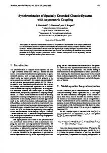
In the sequel, we will use the state variables x1, x2, x3 to represent the states in the first model, and x4, x5, x6 for the states in the second model. The chaotic oscillations of x2, x5 and x3, x6 produced by these models, using A = 0.6, for two sets of initial conditions are shown in Figures 1 and 2, where the solid trajectories represent initial conditions [0.1, 0, 0] and the dashed trajectories correspond to [1.1, 0, 0]. These chaotic trajectories are obviously not synchronized.
3
3. CHAOS SYNCHRONIZATION CONTROL In this paper, two methods are introduced for designing the synchronization control signals. The recursive backstepping control design method is presented first, followed by the master-slave control design technique. 3.1 Backstepping Nonlinear Controller The main goal here is to design one control signal u , to be added to eq. (7), such that the two chaotic systems become synchronized. Following Harb et. al. [11], the error signals are obtained as follows: Let: x = x1 , v = x 2 , a = x3 , x ′ = x1′ , v ′ = x ′2 , and a ′ = x3′ Hence, e1 = x1 − x1′ , e2 = x 2 − x ′2 , and are:
e3 = x3 − x3′ . The time derivative for the error signals
e&1 = x&1 − x&1′ = e2
(9)
e&2 = x& 2 − x& 2′ = e3
(10)
e&3 = x& 3 − x& 3′ = − Ae3 − e2 + f ( x1 ) − f ( x1′ ) − u
(11)
Let V1 be a Lyapunov function given as:
V1 = 12 e1 ,
(12)
Then, V&1 = e1e&1 = e1e2
(13)
2
We define e2 d = −e1 , f 2 = e2 − e2 d = e2 + e1 , and introduce another Lyapunov function V2 given as:
V2 = V1 +
1 2
2
f2 ,
(14)
2 Then, V&2 = V&1 + f 2 f&2 = −e1 + f 2 (e2 + e3 )
In the same manner, let e3d = −e2 , function V3 expressed as:
V3 = V2 +
1 2
2
f3 ,
(15)
f 3 = e3 − e3d = e3 + e2 , and introduce the third Lyapunov
(16)
4
2 Hence, V&3 = V&2 + f 3 f&3 = −e1 + f 3 (e3 − Ae3 − e2 + f ( x1 ) − f ( x1′ ) − u )
(17)
In order for V&3 to be negative, the control signal ‘ u ’ can be chosen as follows: u = e3 (1 − A) − e2 + f ( x1 ) − f ( x1′ )
(18)
and the system with the designed control signal ‘ u ’ is obtained as follows:
x&1′ = x2′ x& ′2 = x3′ x& 3′ = − Ax3′ − x ′2 + f ( x1′ ) + u
(19) (20) (21)
3.2 Master – Slave Controller The objective for this kind of controller is rather to design three control signals u1 , u 2 , and u3 , such that the two chaotic systems are synchronized. First, choose error signals as follows:
e1 = x1′ − x1 , e2 = x 2′ − x 2 , and e3 = x3′ − x3 The time derivative of these are;
e&1 = x&1′ − x&1 = u1 + e2
(22)
e&2 = x& 2′ − x& 2 = u 2 + e3
(23)
e&3 = x& 3′ − x& 3 = − Ae3 − e2 + f ( x1′ ) − f ( x1 ) + u 3
(24)
u1 = −e1 − e2
(25)
u 2 = − e 2 − e3
(26)
u 3 = −e3 + Ae3 + e2 + f ( x1 ) − f ( x1′ )
(27)
Hence, the system with control signals is obtained as follows:
x&1′ = x2′ + u1 x& 2′ = x3′ + u 2 x& 3′ = − Ax3′ − x2′ + f ( x1′ ) + u 3
(28) (29) (30)
5
4. NUMERICAL SIMULATIONS In the following, we present our numerical simulation results of the chaotic systems above, as the control signals are introduced into the models at t = 30ms. 4.1 Synchronization Using the recursive backstepping controller: For the two chaotic systems, eqs. (1) - (3) and eqs. (19) - (21), Figure 3 shows the time history for the system trajectories with and without synchronization controllers. The solid trajectory represents the uncontrolled system ( u is zero), whereas the dashed one represents the controlled system. Clearly, upon applying the control signal, the two chaotic trajectories become synchronized even though their initial conditions, hence their time behaviors, were different.
4.2 Synchronization Using Master-Slave Controller: Similar to the above simulations, Figure 4 shows the time history for the controlled and uncontrolled systems. Prior to t = 30ms, all control signals u1 , u 2 , and u 3 are zero, and the chaotic trajectories are not synchronized. As soon as the control signals are applied, synchronization is achieved and the two systems follow each other. 5. CONCLUSIONS We have presented two methods for chaotic system synchronization have been presented; nonlinear recursive backstepping and master-slave. The control signals required to achieve synchronization are derived so that the error dynamics are asymptotically stable. We have demonstrated that the nonlinear recursive backstepping method can be used to design a control signal that achieves synchronization between chaotic signals representing different initial conditions. We have also shown that the master-slave method can be utilized to design three control signals to accomplish the synchronization. The study demonstrates a promising technique which can be applied in secure communication applications, whereby a chaotically-transmitted information-bearing signal can be faithfully recovered via synchronization.
6
REFERENCES [1] A. Nayfeh and Balanchandra, ”Applied Nonlinear Dynamics”, John Wiley, New York, (1994). [2] E. N. Lorenz, “Deterministic nonperiodic flow”, J. Atmos. Sci. 20, 130-141, (1963). [3] O. E. Rossler, “An equation for continuous chaos”, Phys. Lett. A 57, 397-398, (1976). [4] O. E. Rossler, “An equation for hyperchaos”, Phys. Lett. A 71, 155-157, (1979). [5] C. Hayashi, “Nonlinear Oscillations in Physical Systems”, McGraw-Hill, New York, (1964). [6] R. N. Madan, “Chua’s Circuit: A Paradigm for chaos”, World Scientific, Singapore, (1993). [7] L. Pecora and T. Carroll, “Synchronization in Chaotic Systems”, Physical Review Letters, Vol. 64, pp. 821-823, 1990. [8] L. pecora and T. Carroll, “Driving systems With Chaotic Signals”, Physical Review Letter, Vol. 44, pp. 2374-2383, 1991. [9] L. J. Kocarev, K. S. Eckert, and L. O. Chua, “Experimental Demonstration of Secure Communication Via Chaotic Synchronization”, World Scientific Series on Nonlinear Science, series B, Vol. 1, pp. 371-378. [10] T. L. Carroll, G. A. Johnson, and L. M. Pecora, ”Parameter-Insensitive and NarrowBand Synchronization of Chaotic Circuits”, Int. Journal of Bifurcation and Chaos, Vol. 9, No. 11, pp. 2189-2196, 1999. [11] A. Harb, A. Zaher, and M. Zohdy, “ Nonlinear Recursive Backstepping Chaos Control, ACC- Alaska, (2002). [12] Hassan Khalil. “Nonlinear Systems”, Prentice Hall, 2nd Edition, 1996. [13] Ahmad M. Harb, ”Nonlinear chaos control in a permanent magnet reluctance machine”, International Journal of Chaos, Solitons and Fractals, 19, pp 12171224, 2004. [14] Sprott, J. C., “Simple chaotic systems and circuits”, American Journal of Physics, 68, pp. 758-763, 2000. [15] Bai, E., Lonngren, K., and Sprott, J. C., “On the synchronization of a class of electronic circuits that exhibit chaos”, Chaos, Solitons, and Fractals, 13, pp. 1515-1521, 2002.
7
4
3
2
0
X
2
and
X
5
1
-1
-2
-3
-4 0
10
20
30
40
50 Tim e
60
70
80
90
100
Figure 1: Unsynchronized trajectories x2 (solid, initial conditions 0.1, 0, 0) x5 (dotted, initial conditions 1.1, 0, 0)
4
3
2
0
X
3
and
X
6
1
-1
-2
-3
-4 0
10
20
30
40
50 Tim e
60
70
80
90
100
Figure 2: Unsynchronized trajectories x3 (solid, initial conditions 0.1, 0, 0) x6 (dotted, initial conditions 1.1, 0, 0)
8
4
3
2
and X
6
1
X
3
0
-1
-2
-3
-4 0
10
20
30
40
50 Tim e
60
70
80
90
100
Figure 3: Synchronized x3 and x6 (using backstepping control) after 30 seconds.
3
2
0
3
X and X
6
1
-1
-2
-3 0
10
20
30
40
50 Tim e
60
70
80
90
100
Figure 4: Synchronized x3 and x6 (using Master-Salve control) after 30 seconds.
9