Dec 1, 2010 - Demonstration of Atom LEAP Energy Calipers: Kernel Space . .... http://www.intel.com/products/desktop/motherboards/d945gclf2-d945gclf2d/ ...
The Atom LEAP Platform For Energy-Efficient Embedded Computing: Architecture, Operation, and System Implementation Digvijay Singh1, Peter A. H. Peterson2, Peter L. Reiher2 and William J. Kaiser1 Electrical Engineering Department, University of California, Los Angeles Computer Science Department, University of California, Los Angeles December 1, 2010
Table of Contents 1. 2. 3. 4.
Abstract ........................................................................................................................................ 2 Overview of Low‐power Energy Aware Platform (LEAP) Systems ........................... 2 LEAP Platform Development ................................................................................................ 3 The Atom LEAP Platform ........................................................................................................ 3 1.1. Distribution and Community Access: ........................................................................................ 3 1.2. Performance: ........................................................................................................................................ 4 1.3. New Deep Inspection of Computing Platform Energy‐Sensitive Operation ............. 4 1.4. Architecture .......................................................................................................................................... 4 5. Atom LEAP Synchronization Systems ................................................................................ 7 6. Atom LEAP Synchronization Approach Validation ........................................................ 8 7. Atom LEAP Synchronization and Sampling System ................................................... 10 8. Atom LEAP Synchronization and Sampling System Validation .............................. 10 9. Atom LEAP Developer Interface ....................................................................................... 12 10. Demonstration of Atom LEAP Energy Calipers: Kernel Space ............................. 13 11. Atom LEAP Power Sensing Systems .............................................................................. 15 12. Summary ................................................................................................................................ 15 13. References ............................................................................................................................. 16 14. Appendix A: Atom LEAP Bill of Materials .................................................................... 18 15. Appendix B: Atom LEAP Hardware System Assembly ............................................ 18 16. Appendix C: Atom LEAP DAQ Card Interface .............................................................. 20 17. Appendix D: Atom LEAP Software System Usage ...................................................... 21 18. Appendix E: Atom LEAP Test‐bed Assembly Pictures ............................................. 27
1. Abstract This Technical Report provides a review of a new embedded computing platform enabling research, education and training, and product development based on the Intel Atom processor architecture. This introduces a dramatic advance in the capability for direct characterization of energy and power dissipation in embedded computing platforms and the associated capabilities for optimization of performance and energy. This report includes development, usage, and example operation and results with platform applications in mobile computing, distributed sensing, network routing, and wireless access point implementation. In each case, Atom LEAP is intended to provide both a reference design and a high throughput, easily implemented solution with an unprecedented advance in the capability for characterizing energy usage at a level of computing task and operating system detail substantially superior to prior methods.
2. Overview of Low-power Energy Aware Platform (LEAP) Systems A broad range of embedded networked sensor applications have appeared for large-scale systems focused on the most urgent demands in environmental monitoring, security, and other applications. These applications not only introduce important demand for Embedded Networked Sensing (ENS) systems, they also introduce fundamental new requirements that lead to the need for new ENS embedded architectures, associated algorithms, and supporting software systems. New requirements include the need for diverse and complex sensor systems that present demands for energy and computational resources as well as for broadband communication. Sensing resources include imaging devices, chemical and biological sensors, and others. Computational system demands for new ENS applications now include image processing, statistical computing, and optimization algorithms required for selection of proper sensor sampling. The LEAP platform has introduced a new embedded system design where components are not selected exclusively for low average power dissipation, but instead are selected with both energy and performance criteria to achieve highest energy efficiency and lowest system energy dissipation for a specific measurement objective. LEAP technology has been applied to embedded networked sensing, [McIntire2006] energy-aware routing, [Stathopoulos2007] energy-efficient embedded computing, [Stathopoulos2008] and energy-efficient multicore computing [Ryffel2009]. This platform includes a new energy accounting capability necessary for in-field, adaptive optimization of energy and performance, including methods that may only operate if provided with real-time knowledge of subsystem energy dissipation. LEAP energy accounting is a process of both energy measurement and attribution to the responsible system task or application. Through the use of synchronized energy measurements across the platform’s power domains, the LEAP architecture is able to assign energy usage to high level system operations, often spanning multiple hardware resources. This energy accounting feature allows runtime assessment of energy costs, enabling adaptive behavior based upon energy specific goals. This architecture also includes energy management through scheduling of component operation.
2
Thus, it is then possible to select the most energy efficient components to meet the demands of each sensing task. It is important to note that the LEAP architecture is necessary since, run-time measurement of energy integrated with the platform is required for optimization of energy and performance for many important applications. A series of critical characteristics for determining platform energy dissipation and sensor node platform performance are in fact only known only at runtime. For example, the dynamic nature of events means that as time evolves, data-dependent processing requirements will demand that platform schedules adapt. As an example, processor resource conflicts resulting from the requirements for both processing sensor data (in order to derive event information) while also maintaining network communication between nodes, presents a resource conflict that can be determined only at runtime due to the inherently unpredictable nature of events.
3. LEAP Platform Development The LEAP platform has proceeded through generations beginning with LEAP-1 based on the PXA255 ARM processor [McIntire2006], and then LEAP-2 based on the PXA270 processor and ARM11 architecture [Stathopoulos2008]. The LEAP Server system then was developed to provide support for server-class computing platforms.[Ryffel2009] The enabling components for LEAP2 included an ASIC (implemented with a low power ASIC sampling system accessible to the ARM11 address/data bus). These sampling systems enabled all memory, storage, processor, and peripheral component current levels to be sampled at a rate greater than 1 kHz per channel. LEAP-1 and LEAP-2 have been successful in research and instruction in many programs. LEAP-2 is entering a commercial product in seismic monitoring.
4. The Atom LEAP Platform The Intel Atom processor is appearing in a broad range of embedded products ranging from mobile devices to network appliances. Its support in the Green Edge Networking program provides the capability for development of a wide range of test-beds and development systems. The development of Atom LEAP is intended to provide the following benefits:
1.1. Distribution and Community Access: 1) Low cost: a. The Atom Intel motherboard is low cost and readily available. 2) Accessibility: a. The components for Atom LEAP are low cost and are easily added to the platform. 3) Extensibility: a. The Atom LEAP motherboard provides a reference design with a wide range of peripheral and network interfaces and storage system interfaces. The
3
construction of energy-aware network appliances, energy-aware sensing platforms and testbeds is quite practical now.
1.2. Performance: 1) The Atom LEAP system departs from prior LEAP architectures by relying on peripheral, USB-interface, high speed analog sampling system. a. Today, this uses the National Instruments USB-6215 DAQ system providing high speed analog sampling in both single-ended and differential forms. 2) This system enables an advance in sampling speed over prior platforms 3) The new architecture also presents a challenge for event synchronized sampling. This challenge has been addressed and the solution adopted enables a dramatic step forward in platform capability.
1.3. New Deep Inspection of Computing Platform Energy-Sensitive Operation Atom LEAP introduces new high resolution synchronization methods that improve both performance and ease of use. LEAP architectures enable sampling at high speed integrated with kernel systems. However, these kernel systems were not configurable at run time. Further previous LEAP systems did not enable resolution of energy usage for the combination of user space and kernel space computing including interrupt and system call energy investments. The Atom LEAP system has adopted several new architecture advances. First, the Atom LEAP system leverages the Linux kprobes technology [Panchamukh2004]. This permits the runtime insertion of an inspection module that enables LEAP “energy calipers” to be placed at any location in the kernel code sequence of control. This enables fast instrumentation of a new system. There are many, diverse and fundamental measurements that were not previously possible that may now be accessible. Second, the sampling system and platform are synchronized through an event mechanism that enables instrumentation of short time scale, ephemeral events including kernel services (system calls and interrupts). This is a significant breakthrough for Green Edge network applications in that we are aware of no prior work that has quantified energy investment by these kernel services or further have provided attribution of them to specific tasks and users.
1.4. Architecture The Atom LEAP platform is shown below in Figure 1. This is based on the Intel Atom N330 Motherboard with documentation here: http://www.intel.com/products/desktop/motherboards/d945gclf2-d945gclf2d/d945gclf2d945gclf2d-overview.htm
4
This includes support for: 1) The Intel Atom N330 dual core processor. 2) Dual and multicore embedded systems are now becoming common for their performance and energy efficiency advantages. This platform permits us direct access to each core’s energy dissipation. This is a breakthrough for many research opportunities. 3) Eight USB 2.0 ports 4) This affords many extension 5) Two Serial SATA ports 6) Ethernet interfaces 7) This enables research on energy efficient storage and IO scheduling 8) One parallel ATA IDE interface 9) One serial port 10) One parallel port 11) One PCI port 12) Graphics and audio interfaces Support and drivers are available for a wide range of wireless network interfaces. The Atom LEAP architecture is shown in Figure 1. The N330 dual core processor, SDRAM, Storage, and Network interfaces, are monitored by the high speed sampling system. Synchronization methods, to be discussed, enable access to power dissipation data that is then synchronized with kernel events. This will be available with synchronization for events in each core. The components and finally a complete system is shown in Figures 2 and 3. It should be noted that the platform can be packaged in a small module.
5
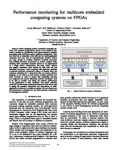
Figure 1. The Atom LEAP Platform architecture for the dual core Atom N330 processor. The Atom platform includes the processor and Graphics and Memory Controller Hub, I/O Controller Hub, and the Legacy I/O Controller. The Analog Sampling system detects voltage drops across current sensing resistors for the components indicated. The Sync Signal is generated by the I/O Controller at its RS-232 serial interface as the DTR line. This is sampled also by the analog sampling system.
Figure 2. The Atom LEAP Platform primary components including embedded motherboard with a wide range of diverse interface options as well as the analog sampling module at lower left.
6
Figure 3. The Atom LEAP Platform. The Atom platform is shown next to the optional chassis. Wiring between the DAQ and platform is shown. The Atom LEAP wiring harness can be supplied as a kit item or constructed.
5. Atom LEAP Synchronization Systems As discussed in previous Green Edge documents, the Atom LEAP platform relies on a sampling system module that provides direct measurement of subsystem power dissipation. According to the Atom LEAP architecture, the processor Time Stamp Counter (TSC) is then synchronized directly with the sampling system module. This, in turn permits power and energy measurements in kernel and user space control sequences that have previously been inaccessible. This section of the report briefly describes development and validation of synchronization. The Atom LEAP system relies on a synchronization method that directly links the time base associated with the a CPU core Time Stamp Counter (TSC) with that of an external continuously operating sampling system that acquires platform subsystem current and supply voltage measurements. This synchronization is, in turn, based on the usage of a signal generated by direct output of a hardware reference that is sampled by the external sampling system. Of course, a critical requirement is to prove that these signals are synchronized and to also determine the characteristics of time base drift between subsystems to ensure that a periodic synchronization signal (with sufficiently low repetition rate to present negligible platform operating overhead) provides sufficiently accurate synchronization. Here, sufficient accuracy is established if drift in time base synchronization remains less than a small fraction of a sample period. This approach enables direct relationship between analog sampling of platform power and processor TSC values. Since the TSC is then immediately accessible to kernel systems, direct power and energy measurement synchronized with kernel events is now possible. While latency must be verified, low latency is expected as a result of platform architecture. The serial port UART system is integrated into an Intel Legacy I/O Controller bridge as shown in Figure 1. This evaluation seeks to validate that serial port signals are generated with low latency with respect to events initiated by the sequence of control defined by kernel code. In particular, the execution of sampling of TSC values and the initiation of a serial port pulse must be coincident within a time interval no greater than a sampling interval of the analog current sampling system.
7
6. Atom LEAP Synchronization Approach Validation An experiment was designed to create an observable and immediate change in power dissipation initiated by a well-defined kernel event while at the same time introducing a serial port signal. This kernel event was created by simultaneously monitor power dissipation by the memory subsystem, and the serial port signal during a transition between two operating states. The two states include first a loop over NOP operations (implemented with cpu_relax() ) and then followed by a loop over memory block copy operations with block sizes of 1MB, exceeding the L2 cache size of 512KB. The transition between the two loops is anticipated to introduce a large change in memory power dissipation. This proposed operation is confirmed as shown in Figures 1, 2, and 3. Note that as observed in every data set to date, the serial pulse rise time is such that it is always observed to rise between minimum and maximum values during one sample period. It thus offers a sufficiently high resolution sample probe for this sample rate of 10 kHz. The coincidence of sampling, serial port signal assertion and memory power events confirms the low latency operation of the serial port signal. With this validation, we now proceed with the usage of the serial port synchronization to implement automated synchronized sampling.
Figure 4. Memory SDRAM subsystem power dissipation at an event corresponding to the initiation of a large block memory copy of a size in excess of the CPU L2 cache size. This event includes a serial synchronization signal and sampling of the TSC.
8
Figure 5. Data of Figure 1 shown at high resolution.
Figure 6. Data of Figures 1 and 2 highlighting the time region at the event where memory copy, serial sync signal and TSC sampling occurs.
9
7. Atom LEAP Synchronization and Sampling System The Atom LEAP Synchronization System relies on interaction between a kernel module and a user space application process. The kernel module includes capability for generating the serial port synchronization signal while measuring the TSC value at which this signal is asserted. The user space process commands the kernel module signal assertion at a regular and configurable interval. The default period is currently 100 milliseconds. The user space process is also tasked with acquisition of data from the DAQ sampling system. This process computes a continuously updated linear model relating TSC and sample clocks. This takes advantage of the presence of data in the DAQ sampling record that contains the serial synchronization signal. The linear model relating the TSC and sample clocks is solved for by comparing TSC and sample index values at the successive events. The linear relationship includes a Synchronization Scale Factor (SSF) (the ratio of TSC rate divided by sample rate) and a Sample Index Offset (SIO) value.
8. Atom LEAP Synchronization and Sampling System Validation Experimental validation has been performed by creating kernel events including both operations that induce memory or processor power change and serial port signals while recording TSC values at each event. First, drift in the values of computed relationship between TSC and sample counts has been determined. This was evaluated by initiating a synchronization event (as above applying two successive synchronization signals) and then observing drift using the methods of Figures 1 through 3. As shown in Figure 4, drift is less than one sample over a period of several seconds. This establishes that 100 millisecond synchronization refresh periods are adequate to ensure less than one sample count error. For continuous operation of the automated synchronization system, experimental analysis also shows that variations in SSF and SIO account for less than one sample index value over lengthy intervals as shown in Figure 5.
10
Figure 7. Experimental results for TSC and sample synchronization drift. Note that over a 3 second period, accumulated drift is much less than one sample interval.
Figure 8. Variation in computed value of Synchronization Scale Factor with time. Note that this variation accounts for less than one sample of synchronization variation. Experiment Relative Time (seconds) 2.2 7.4 16.6
Time Stamp Counter Measured Value at Event Time 275027181544764 275035473163152 275050137785508
Sample Index Measured Value at Event Time
Sample Index Predicted Value at Event Time
Sample Index Prediction Error
21768 73721 165604
21769 73721 165603
1 0 1
Table 1. Evaluation of synchronization stability by comparison of actual and computed Sample Index values from values of TSC and SSF and SIO values.
11
9. Atom LEAP Developer Interface The new Atom LEAP system presents an output data set that includes Sample Index (SI), CPU power, storage system power (HDD), main memory SDRAM power (RAM), sync signal value, and TSC. The TSC values are computed using the synchronization system. A typical record is shown in Figure 6. Note that now a developer has complete access to all power data and requires only knowledge of TSC value within a sequence of control to implement “Energy Calipers”. SI 994 995 996 997 998
CPU 2.442 3.849 2.363 3.928 3.218
HDD 1.505 1.982 0.88 1.061 1.308
RAM 2.079 0.942 0.882 2.233 1.735
Sync -1.065 -1.065 -1.065 1.091 1.091
TSC 275023865598993 275023865758587 275023865918180 275023866077782 275023866237372
Figure 9. Typical output data file for the Atom LEAP sampling system. Data values include the sample index value (SI), CPU Power, HDD Power, RAM Power, Sync signal voltage, and Time Stamp Counter (TSC) value. The TSC is a derived quantity computed by the Atom LEAP synchronization system.
12
10. Demonstration of Atom LEAP Energy Calipers: Kernel Space A demonstration of Energy Calipers has been developed. This seeks to measure the energy cost associated with proper and improper use of processor L1 and L2 cache resources. This demonstration applies a system that performs a memory copy in a loop for a number of cycles. The memory copy size and number of cycles are scaled in subsequent to probe the influence of cache size (both L1 and L2 on memory copy size) while maintaining total copy payload constant. The remarkably convenient method for instrumentation of code to enable this is indicated below with a code segment from the demonstration module included in the Appendix. Note below that the developer need only add the 64bit read of TSC prior to and after events of interest and to subsequently report these values to the kernel log buffer. It is important to note that powerful interfaces may now be developed that provide many power and energy inspection operations with small processor overhead. /* Read current TSC value - STARTING CALIPER */ rdtscll(tsc_start); /* Memory-copy loop */ for(i=0; i zypper install python gcc make
Note that you must have a working internet connection before these commands will work. This can be accomplished by using the Ethernet card on the Atom motherboard to connect to the LAN. Then the wired connection is configured by using the “Network Manager” GUI to have a working internet connection. Finally, we update the system using the following command as root: #> zypper update
Now that our operating system is running, we install the drivers and programming interfaces for the DAQ card. The basic package that we want to install is the Linux version of ‘NIDAQmxBase 3.4’. This package can be downloaded along with the README [NI2010]. The README contains a section with detailed instructions on installing the drivers and programming interfaces on openSUSE. We only follow these instructions from Steps 1 to 5, but instead of following the last step we download the ‘NIDAQmxBase 3.3’ package [NI2009]. Now, as root, we extract ‘NIDAQmxBase 3.4’ and copy the files to ~/bin. Then, the ‘NIDAQmxBase 3.3’ package is extracted and the files are copied to ~/bin/nidaqmx3_3/. After this we execute the following command sequence:
20
#> cd ~/bin #> chmod +x INSTALL #> ./INSTALL
At the terminal answer the following for the installation prompts: Do you want to install NI-DAQmx Base for C? No Do you want to install NI-DAQmx Base USB Device Support? Yes
Next we follow these set of commands: #> #> #> #>
cd ~/bin/nidaqmx3_3 rpm --install labview82-rte-8.2.1-2.i386.rpm rpm --install nidaqmxbase-cinterface-3.3.0-f0.i386.rpm yast2 --install libstdc++33
Now we find the Linux version we are running using the command ‘uname –r’ and this replaces in the following set of commands (for example, on our system was 2.6.31.14-0.4): #> #> #> #> #> #>
cd /usr/src/linux- make mrproper zcat /boot/symvers--default.gz > Module.symvers make cloneconfig make modules_prepare updateNIDrivers
Finally, we reboot and then test our system using the following command to detect our DAQ card: #> lsdaq --------------------------------------------------------------Detecting National Instruments DAQ devices: Found the Following DAQ devices: NI USB-6215: “Dev1” (USB0: 0x3923::0x7271::01551AC9::RAW) ---------------------------------------------------------------
The README also contains a section for the C programming interfaces. Examples are also provided to help developers write C code to program the DAQ. This will probably not be required as we provide code for performing configuration and sampling for the DAQ card as part of our software system for the Atom LEAP.
17. Appendix D: Atom LEAP Software System Usage The software is available as a package called ‘atom_LEAP-1.0.zip’ along with this document. First, we extract this package to the folder /usr and then build the modules as root: #> mv atom_LEAP-1.0.zip /usr/ #> cd /usr
21
#> #> #> #>
unzip atom_LEAP-1.0.zip cd /usr/atom_LEAP chmod –R +x * ./build.sh
Next, we set-up the synchronization module. We need to find the address of the ‘do_timer’ function in the Linux kernel. For this we run the following commands with the value of obtained using the command ‘uname –r’: #> cat System.map- | grep do_timer c025d560 T do_timer c08aa6a8 D tick_do_timer_cpu
Thus, on our system we obtained c025d560 as the address of ‘do_timer’. We now edit the file /usr/atom_LEAP/code/sync/probe_set_address.sh using a text editor and put the address of ‘do_timer’ in it: #!/bin/sh echo c025d560 > /proc/probe/address dmesg | tail –n 1
# Put address of do_timer() here!
Then, we insert the synchronization module into the kernel. This particular step must be performed every-time the machine is rebooted: #> insmod /usr/atom_LEAP/code/sync/probe.ko
Our synchronization system has now been set-up and is ready for use. We are now capable of sampling energy/power data for our system using the DAQ card. It is advisable to exit super-user (root) mode now and use ‘sudo’ for all further commands. This can be accomplished using the following command: #> sudo /usr/atom_LEAP/code/sampling/start_sampling 2> data.txt Output can be redirected to a file using pipes. All power data is in Watts. Initiating data sampling (this may take a few seconds) … Data Sampling started at a rate of 10000.00Hz! Press Ctrl-C to stop and exit. [62218.180110] Kprobe address set to c02d560 [62218.248530] Synchronized! Core = 1 TSC = 131256430081464
This will redirect all data samples to the file ‘data.txt’. Pressing Ctrl-C on the keyboard will stop the sampling process: ^C[62248.183110] Probe Unregistered ^C[62248.183110] Probe Unregistered #>
22
Now the raw power data exists in ‘data.txt’. We can synchronize the power data with the TSC on the Atom Processor using the following command: #> sudo python /usr/atom_LEAP/code/sync/sync.py data.txt> sync_data.txt
We have obtained the synchronized power data in the file ‘sync_data.txt’. This can now be used as the developer wishes. To further help users, we have provided examples and tools in our software package to enhance the utility of the power data that the Atom LEAP system generates. One such tool we would like to introduce is the ‘energy caliper’. It provides Atom LEAP users the ability to estimate the power/energy usage for sections of their modules or programs. We have developed energy calipers in two flavors namely the ‘kernel-space energy calipers’ and ‘user-space energy calipers’. Kernel-space energy calipers are to report energy/power usage for sections of code within kernel modules [Salzman2001]. We will present an example to elucidate how this tool works. The module /usr/atom_LEAP/code/kernel_energy_caliper/kernel_caliper_example.c is used in our demonstration. This simple kernel module is quite straight-forward and basically performs memory copies using kernel memory. The important parts to notice in the code are the reads of the TSC (time-stamp counter) register and logging of its value in the kernel log buffer: /* Read current TSC value – STARTING CALIPER */ rdtscll(tsc_start); /* Memory-copy loop */ For(i=0; i sudo /usr/atom_LEAP/code/sampling/start_sampling 2> data.txt Output can be redirected to a file using pipes. All power data is in Watts. Initiating data sampling (this may take a few seconds) … Data Sampling started at a rate of 10000.00Hz! Press Ctrl-C to stop and exit. [62218.180110] Kprobe address set to c02d560 [62218.248530] Synchronized! Core = 1 TSC = 131256430081464
In the other terminal, we insert our compiled kernel module to begin execution: #> sudo /sbin/insmod /usr/atom_LEAP/code/kernel_energy_caliper/kernel_c aliper_example.ko
After execution of the code has finished, we remove the module (this step is optional, but encouraged): #> sudo /sbin/rmmod kernel_caliper_example.ko
Now, back in the first terminal we stop the data sampling by pressing Ctrl-C on the keyboard: ^C[62248.183110] Probe Unregistered ^C[62248.183110] Probe Unregistered #>
Next, we synchronize the obtained data with the Atom processor’s TSC using our synchronization system: #> sudo python /usr/atom_LEAP/code/sync/sync.py data.txt> sync_data.txt
Finally, we can now report then energy/power during the execution of the memory-copy loop by using the following command. Note that the report is only generated for the most recent kernel module execution and previous executions will be ignored: #> sudo python /usr/atom_LEAP/code/kernel_energy_caliper/kernel_caliper _report.py sync_data.txt CPU_Energy (J) = 20.477718 HDD_Energy (J) = 2.572131 Bridge_Energy (J) = 25.904280 RAM_Energy (J) = 3.230877 CPU_Average_Power (W) = 10.078113 HDD_Average_Power (W) = 1.265875 Bridge_Average_Power (W) = 12.748797 RAM_Average_Power (W) = 1.590077
User-space energy calipers are akin to Kernel-space energy calipers, but instead allow us to estimate energy/power during execution of sections of user-space programs instead of kernel modules. The file /usr/atom_LEAP/code/user_energy_caliper/user_caliper_example.c
24
contains the program used in our demonstration. This is a standard C program with a few notable exceptions. First, we look at the following snippet of code: typedef unsigned long long ticks; static __inline__ticks getticks(void) { unsigned a,d; asm(“cpuid”); asm volatile (“rdtsc”: “=a” (a), “=d” (d)); return (((ticks)a) | (((ticks)d) sudo /usr/atom_LEAP/code/sampling/start_sampling 2> data.txt Output can be redirected to a file using pipes. All power data is in Watts. Initiating data sampling (this may take a few seconds) … Data Sampling started at a rate of 10000.00Hz! Press Ctrl-C to stop and exit. [92218.380113] Kprobe address set to c02d560 [92218.648533] Synchronized! Core = 0 TSC = 161256440081513
Next, in the other terminal we execute the compiled version of our example energycaliper code. Note that we must assign a very high real-time priority using ‘chrt’ to our program to reduce chances of pre-emption. This will help us to eliminate erroneous energy data that may be introduced by other running processes. This was not a problem for the Kernel-space energy calipers as kernel module insertion cannot be pre-empted. For more information on real-time process scheduling in Linux use the command ‘man chrt’: #> sudo chrt 99 /usr/atom_LEAP/code/user_energy_caliper/user_caliper_ex ample
Once execution of our code has completed we wait for a few seconds for data to be written to the file and then, in the first terminal, we stop the sampling process: ^C[99245.143610] Probe Unregistered ^C[99245.143610] Probe Unregistered #>
We now synchronize the raw data with the TSC on the Atom processor:
26
#> sudo python /usr/atom_LEAP/code/sync/sync.py data.txt> sync_data.txt
Finally, we can report the power/energy for the sections of code we had marked with our energy calipers: #> sudo python /usr/atom_LEAP/code/user_energy_caliper/user_caliper_rep ort.py sync_data.txt This is the AES-128 openSSL test! CPU_Energy (J) = 16.951892 HDD_Energy (J) = 2.238894 Bridge_Energy (J) = 21.797209 RAM_Energy (J) = 1.253892 CPU_Average_Power (W) = 10.085009 HDD_Average_Power (W) = 1.331961 Bridge_Average_Power (W) = 12.967582 RAM_Average_Power (W) = 0.745965 This is the RC2 openSSL test! CPU_Energy (J) = 36.357257 HDD_Energy (J) = 6.060418 Bridge_Energy (J) = 46.841994 RAM_Energy (J) = 2.801224 CPU_Average_Power (W) = 10.059559 HDD_Average_Power (W) = 1.676835 Bridge_Average_Power (W) = 12.960543 RAM_Average_Power (W) = 0.775061
18. Appendix E: Atom LEAP Test-bed Assembly Pictures
27
Figure 12. The Atom LEAP Platform with current sensing access leads shown. The Atom processor heatsink is at the foreground with memory DIMM at left and digital and media interfaces at right.
Figure 13. The Atom LEAP Platform with current sensing access leads shown. The memory DIMM is at the foreground.
Figure 14. The pinout of the NI DAQ USB-6215 card are shown here. Connections will be made to the Analog Input (AI) pins of the DAQ card using our current sensing leads. This allows us to obtain power usage for various components.
28
Figure 15. The Atom Platform with current sensing access leads shown. The memory DIMM is at the foreground. The connections to the current sensing resistor in the DIMM riser card is shown.
Figure 16. The Atom The Atom LEAP Platform is shown with attention to the CPU power supply system. The inductor component of the CPU power supply PWM system is seen at center. This is the solenoidal inductor (with copper windings) flanked by two electrolytic capacitors.
29
Figure 17. The Atom LEAP Platform is shown with attention to the DIMM and Memory and Graphics Hub chip power supply system. The inductor component of the CPU power supply PWM system is seen at center. This is the solenoidal inductor (with copper windings) flanked at left by two power MOSFET devices that are components of this PWM system.
30
Figure 18. The Atom LEAP Platform is shown with attention to the CPU power supply system at the board location underneath the PWM system. The current sensing leads are soldered to the inductor terminals that protrude through this board at this location. Soldering of the sense leads is executed with great care to ensure that the board is not damaged.
Figure 19. The Atom LEAP Platform is shown with attention to the DIMM and Graphics and Memory Hub power supply system at the board location underneath the PWM system. The current sensing leads are soldered to the inductor terminals that protrude through this board at this location. Soldering of the sense leads is executed with great care to ensure that the board is not damaged.
31
Figure 20. The standard SATA drive is shown equipped with its current sensing resistor and sensing leads.
Figure 21. The Atom LEAP Platform is shown with attention to cable strain relief practice. It is most important to ensure that mechanical strain is not applied to component connections.
32
Figure 22. The pinout for the serial port of the Intel Atom Motherboard is shown. We are interested in connecting the RTS (pin 7) and GND (pin 5) lines to the DAQ card. These serial port lines are used for synchronizing the DAQ card’s samples with the Atom processor’s TSC.
33