Basri et al. / Malaysian Journal of Fundamental and Applied Sciences Special Issue on Medical Device and Technology (2017) 546-552
RESEARCH ARTICLE
The effect of flow rate characteristic on biodegradation of bone scaffold Hasan Basri a,*, Jimmy Deswidawansyah Nasution a, Ardiyansyah Syahrom b,c, Mohd Ayub Sulong b,c, Amir Putra Md.Saad b, Akbar Teguh Prakoso a, Faisal Aminin a a b
c
Department of Mechanical Engineering, Faculty of Engineering, Universitas Sriwijaya, Inderalaya 30662, Kabupaten Ogan Ilir, Indonesia Department of Applied Mechanics and Design, Faculty of Mechanical Engineering, Universiti Teknologi Malaysia, 81310 UTM Johor Bahru, Johor, Malaysia Sports Innovation and Technology Centre (SITC), Institute of Human-Centred and Engineering (IHCE), Universiti Teknologi Malaysia, Skudai 81310 UTM Johor Bahru, Johor, Malaysia
*Corresponding author:
[email protected]
Article history Received 16 October 2017 Accepted 6 December 2017
Abstract This paper proposes an improved modeling approach for bone scaffolds biodegradation. In this study, the numerical analysis procedure and computer-based simulation were performed for the bone scaffolds with varying porosities in determining the wall shear stresses and the permeabilities along with their influences on the scaffolds biodegradation process while the bio-fluids flow through within followed by the change in the flow rates. Based on the experimental study by immersion testing from 0 to 72 hours, the specimens with different morphologies of the commercial bone scaffolds were collected into three group samples of 30%, 41%, and 55% porosities. As the case of the cancellous bone morphology, the morphological degradation was observed by using 3-D CAD scaffold models based on microcomputed tomography images. By applying the boundary conditions to the computational fluid dynamics (CFD) and the fluid-structure interaction (FSI) models, the wall shear stresses within the scaffolds due to flow rate variation had been simulated and determined before and after degradation. The increase of flow rates is given to lift the pressure drop for scaffold models with porosities lower than 50% before degradation. As the porosity increases, the pressure drop decreases with an increase in permeability within the scaffold. The flow rates have significant effects on scaffolds with higher pressure drops by introducing the wall shear stresses with the highest values and lower permeability. These findings demonstrate the importance of using accurate computational models to calculate shear stress and determine experimental conditions in perfusion bioreactors for tissue engineering more accurate results will be achieved to indicate the natural distributions of fluid flow speed, wall shear stress, and pressure. Keywords: Bone scaffold, biodegradation, porosity, shear stress, permeability, flow rate © 2017 Penerbit UTM Press. All rights reserved
INTRODUCTION Physiological activity is very important for bone homeostasis. The generated mechanical loading from physiological activity induces a mechanical stimulus of fluid flow [1] due to pressure differentials. Routine physical activities such as walking, jogging, stair-climbing, and stumbling result in different loadings on the human bone. The average loading during walking, jogging and fast walking, stair climbing, and stumbling are 3.1 x body weight (BW), 6.2 x BW, and 8.7 x BW, respectively. The BW is based on a 75 kg [2,3]. These variations in mechanical loading generate different bone strains (1000–3500 µɛ) that create the pressure difference in bone [4]. Consequently, different flow rates induce different flow rates of the bone marrow are generated. These variations in flow rates induce different shear stress levels that are experienced by bone cells [5]. Mechanical stimulation demonstrates better osteogenic differentiation than static culture because bone cells are subjected to fluid flow [6,7]. Fluid flow is primarily caused by compressive loading of bone as a result of physical activity. Changes in loading, e.g., due to protracted periods of bed rest or microgravity in space are associated with altered bone remodeling and formation in vivo. In vitro, it has been reported that bone cells respond to fluid shear stress by releasing osteogenic signaling factors, such as nitric oxide, and prostaglandins [2]. 546
Evaluating fluid flow mechanism and subsequently, permeability [3] or wall shear stress [4] is an important part because of the direct effects of these parameters on cell bioactivity within scaffolds. A permeable scaffold should allow efficient nutrient and gas diffusion and waste emission through its channels [5]. Determining scaffold permeability is an important factor in predicting cell proliferation, regardless of the fact that permeability can exert opposite effects on different types of cells [6]. Appropriate cellular signals, including those induced by biophysical stimulants, enable the formation of desired tissue inside a scaffold’s pores [7]. Among the well-known biological stimulants, the shear stress that arises from fluid flow exert the most pronounced effect [8]. A number of studies have been conducted to investigate factors that effectively control permeability and wall shear stress. O'Brien et al. [9] carried out experimental and mathematical analysis and found that scaffold permeability depended mainly on porosity. Another study probed into the effect of porosity and pore size on permeability through an experimental and computational analysis [10]. The result indicated that the permeability improved with increasing porosity and pore size. Given major role of fluid flow rates in wall shear stress (WSS), numerous studies have focused on flow-induced shear stresses [8,9,11]. Bartnikowski et al. [4] probed into the effects of scaffold architecture with a porosity of 60% on osteoblast response in
Basri et al. / Malaysian Journal of Fundamental and Applied Sciences Special Issue on Medical Device and Technology (2017) 546-552
perfusion bioreactor and static cell cultures. It was found good agreement in the permeability results derived from CFD and experiments, it was concluded that CFD analysis is a reliable tool for predicting WSS. Zhao et al. [12] performed CFD analysis to investigate the effect of geometrical parameters, such as pore size and shape on WSS. Their finding indicated that pore size more significantly influenced mechanical stimulation within a scaffold than the structural architecture and porosity. In a recent study, the different ranges of WSS were obtained only by modifying scaffold architecture [7]. Apart from mechanobiological movement affects bone scaffold quality with biological environment, many requisites should be met through the micro and macro scale design of a porous structure in scaffolds [13,14]. When it comes to the morphological design, the biomechanical modulation involving with simultaneous consideration of structural and bio-fluidic properties is becoming a vital aspect [15]. From a microscopical point of view, although the main topological features having the significant impact on biological efficiency has been frequently addressed, there are still conflicts between reported data [16]. The minimum pore size of 80 µm has been found to be necessary for an optimum cell penetration in hydroxyapatite scaffolds [17]. Some studies also have found the suggested pore sizes with the values higher than 300 µm could enhance cell proliferation [18,19]. Nevertheless, Murphy et al. [20] had stated that although there was a higher bone formation within scaffolds with 325 µm of pore size, the pore size of 120 µm also showed considerable early additional peak. In addition, a substantial capillary density was reported for pore sizes higher than 140 µm [21] and in the range 300-1200 µm no considerable difference was found in bone formation [22]. As well, in terms of porosity, the values higher than 85% was seen to improve cell penetration up to 400 µm [23] whereas the porosities larger than 75% was suggested to ensure cell proliferation [24]. Furthermore, Danilevicius et al. [25] observed a higher efficiency for the scaffold with the 86% porosity compared the ones with 82% and 90%. Given this disparity and complication, many attempts have been made to quantitatively describe permeability of porous scaffolds to conglomerate main topological features such as porosity, pore architecture, pore size, and interconnectivity through which biological efficiency of pore morphology is being characterized [10,26-28]. The
recent study performed by Syahrom et al. [29] had offered that prismatic plate suggested as a rod model has shown the similar permeability as of natural bone and the higher permeability was attributed to structures comprised of tetrakaidecahedron unit cells. The accuracy of CFD calculations in predicting permeability of regular scaffolds was also studied by Truscello et al. [30] and their results were in good agreement with the experimental data by less than 27% of error. To address this gap, it necessary to consider the mechanical stimulus of fluid flow in determining the degradation behavior of porous Mg in immersion tests. The current study carried out computational simulation base on CFD to determine the effects of different porosity scaffold architecture on physical of human activity and its biodegradation.
MATERIALS AND METHOD Previous research overview Cuboid-shaped (5 x 5 x 3 mm) of commercially available pure magnesium (rod diameter of 24.4 mm and 99.9% purity which was made by Good Fellow Inc, Cambridge, UK) having interconnected holes were fabricated using CNC machine (HAAS, USA). The samples were drilled using a drill bit of 800 µm diameter. The porous magnesium of bone scaffold with varying porosity and surface area can be shown in Fig. 1c [31,32]. The morphology of the specimens is shown in Table 1. Table 1 Morphological details of porous magnesium scaffold specimens [31,32].
Type
Porosity
Surface Area
Volume
Surface area per volume
A
30%
189.30 mm2
52.87 mm3
3580.48 m-1
B
41%
209.81 mm2
44.57 mm3
4704.43 m-1
55%
2
3
6673.07 m-1
C
225.75 mm
33.83 mm
Fig. 1 The dynamic immersion test rig system: a) a schematic view of the test rig, b) a detailed illustration of the fluid medium SBF direction in the chamber, and c) a photograph of three different morphology of bone scaffolds [31,32].
The three groups of specimens with different morphologies were labeled as sample A, B, and C. The samples were fabricated with three different porosities 30%, 41%, and 55%, respectively, which were selected on the basis of the morphology of cancellous bone. For
the experimental test, there were 27 porous magnesium samples were prepared within the scope of this research. The different flow rates of bone marrow across a cancellous bone structure were translated to an in vitro experimental setup, as described in Fig. 1a and 1b [31,32]. A
547
Basri et al. / Malaysian Journal of Fundamental and Applied Sciences Special Issue on Medical Device and Technology (2017) 546-552
laminar flow in a channel with a 41 mm length (L) was set. Three different flow rates, i.e. 0.025, 0.4 and 0.8 ml/min, respectively to perform different mechanical loadings. A chamber was specifically designed with a 2 mm diameter (D) to clamp and hold the specimen in the channel during testing. Two pressure gauges (EMA, China) were placed before and after the chamber to measure the pressure difference in which both were connected to a data acquisition instrument (DAQ, National Instruments, USA). The porous Mg was subjected to immersion tests for the periods of 24, 48 and 72 hours. Once proven, the specimen removed from the bedroom, gently rinsed with deionized water, and then dried under vacuum for 1 hour. Three dimensional model preparation In order to determine the behavior of fluid flow of porous magnesium scaffold, computer-aided design (CAD) models of bone scaffold initially were generated using Solidworks modeling software as shown in Fig. 2. One sample from each porosity (i.e. A, B, and C) and each immersion group (i.e. 24, 48 and 72h) with 0.025 ml/min flow rate, were scanned by means of the micro-computed tomography (µCT) device. For simulation purpose, there only 9 samples were scanned. Raw images with a resolution of 17.20 µm by using a µCT scanner (Skycan 1172, Kontich, Belgium) were taken. In general, µCT datasets provide spatial information, suitable for measurements of various bone parameters such as bone volume, bone thickness bone mineral density and surface area. The procedure to obtain a three-dimensional model from raw µCT images of the bone scaffold illustrates the step-by-step process in Fig. 2. The representative cross-sectional images and the morphology of the specimen after degradation are presented respectively in Fig. 2a and Fig. 2b. The data from µCT images as shown in Fig. 2a is prepared to be exported into MIMICS software (Materialize, Belgium). The volume of interest (VOI) is reduced as much as possible so that the specimen encapsulated by a minimum number of black voxels. After that, the images are transformed into a binary form or simply black and white voxel. The black and white voxel in the micrograph represents the air and solid, respectively. Segmentation or thresholding procedure is conducted by using MIMICS software commands to set the right value of greyscale [33]. This process is iteratively adjusted until the volume of reconstructed 3D model coincides with the actual sample underwent the µCT scanner [34,35]. Finally, the 3D model is obtained with the 3D mask calculate software command as shown in Fig. 2c.
Fig. 2 Illustrations of the preparation process of bone scaffold reconstruction: a) raw data µCT, b) segmentation of image stacks and c) 3D model reconstruction.
Reconstructed 9 samples of porous magnesium specimens as shown in Fig. 3 were exported as stereolithography format (STL) that show the surface network. The STL surface mesh contains a large number of triangles to avoid the loss of geometric details. Boundary condition and material input In the following step, the commercial software, COMSOL was used to transform the surface mesh into the volume mesh. The resulting numerical three dimensional contains tetrahedral elements. For fluid characterization of the porous magnesium scaffold specimen by using CFD, incompressible fluid properties (i.e. simulated body fluid) was used in the scope of this investigation and the values were
548
assumed to have a density = 1000 kg/m3 and dynamic viscosity 0.001 Pa.s.
=
CFD simulation procedure The models for fluid flow analysis were solved by COMSOL solver. The properties of bio-fluid were set to the value of density 1000 kg/m3 and viscosity 0.001 Pa.s, respectively. In order to ensure the fluid flow remains laminar (satisfying Darcy’s law), a low inlet flow rate was imposed at the inlet and zero pressure condition was defined at the outlet (see Fig. 4).
Fig. 3 Photograph comparison morphology between true samples and 3D reconstructed models of bone scaffold after biodegradation.
Fig. 4 The boundary conditions used in CFD simulation
Finally, the average pressure drop was obtained for each model and the permeability coefficient was calculated by Darcy’s law using Eq. (1).
(1) where Q is the volumetric flow rate, A is the cross-sectional area of the specimen (m2), is set for the obtained pressure drop under defined boundary conditions (Pa), L is the specimen length (m), is the fluid viscosity, and k is the intrinsic permeability of the specimen. In order to exclude dimensional effects, the numerical permeability values were normalized by the permeability of a perfectly porous structure with the same boundary condition.
Basri et al. / Malaysian Journal of Fundamental and Applied Sciences Special Issue on Medical Device and Technology (2017) 546-552
Mesh sensitivity study A convergence study was executed where a minimum of 600,000 fluid cells was required for reliable results (see Fig. 5). The velocity value of the analysis had to be independent of mesh density, where the wall shear stress and permeability are directly dependent on the velocity. Roughly, for the period of 2 hours were required to complete the generation of the mesh and another 3 hours were needed to finish the simulation. All simulations were performed on a Dell Precision Workstation T54000 with Intel Xeon microprocessor and RAM of 128 GB.
The permeability of each specimen before degradation was then determined (see Fig. 7). The influence of permeability of the specimen A (30% porosity), B (41% porosity), and C (55% porosity) under different flow rates does not significantly change. The permeability of porous magnesium specimen increases as porosity increases. The significance level of the correlation was 71.59%. The results agree with the previous study [10,32].
Fig. 7 The relationship between permeability and porosity of bone scaffolds under three different flow rates before degradation.
Fig. 5 Convergence study for fluid flow analysis
RESULTS AND DISCUSSION Many devices have been investigated for providing suitable mechanical stimuli to simulate the environment in vivo. The flow chamber used in the research was built to give a steady fluid shear stress and permeability through scaffold in vitro. Since it was hard to validate the fluid wall shear stress generated by existing test method, therefore a computational fluid dynamics were conducted. The SBF flowed through the chamber, generated fluid shear stress on the surface of the scaffold. The shear stress magnitude could be corrected by varying the flow rate of the SBF solution. In order to determine the performance and reliability of the scaffold models in CFD analysis, their pressure drop (∆P) responses to flow rate were tested under three different flow rates 0.025, 0.4 and 0.8 ml/min, respectively. From the CFD results for the three different scaffold porosities as shown in Fig. 6, it was found that the pressure drop (∆P) through the specimens increases linearly as the given flow rate increases. The results sound good with the previously reported experimental work on perfusion experiment in rabbit cancellous bone graft [36]. Thus, these results indicate that the simulation procedure followed the experimental testing.
Figure 8 shows the comparison between permeability values of cancellous bone from previous experimental and simulation studies and permeability of bone scaffolds in the present study. These values were obtained from experimental studies and varied from 2.56 × 10 -11 m2 to 7.43 × 10⁻⁸ m2. The cancellous bone samples were taken from the vertebral body of the calcaneus [37], the femoral bone [36,38,39], and the lumbar vertebrae [40,41]. Based on our extensive literature search, there has been computational simulation work reported on bulk cancellous bone and the permeability values were 1.4 × 10⁻⁷ m2 to 2.8 × 10⁻⁷ m2. In this present study shows permeability values ranging from 2.2 × 10⁻⁷ m2 to 3.94 × 10⁻⁷ m2. The result shows good agreement with bulk cancellous bone on computational simulation in the previous study. The aim of this study was to compare the permeability of bone scaffold with cancellous bone and to determine its relationship with the morphological indices include porosity, pore size, and surface area.
Fig. 8 comparisons between permeability values of cancellous bone from previous experimental and simulation studies and permeability of bone scaffold in the present study.
Fig. 6 Relationship between pressure drop (∆P) and flow rate (Q) before degradation.
The correlation between permeability and porosity of bone scaffold after the immersion test is illustrated in Fig. 9. The permeability of the whole samples increases as the porosity increase. The 0h period indicates the sample before degradation and the 72h period indicates the sample after degradation. The substantial point of 549
Basri et al. / Malaysian Journal of Fundamental and Applied Sciences Special Issue on Medical Device and Technology (2017) 546-552
the correlation is 0.58 for permeability and porosity. Although on that point are numerous reports on the permeability of porous structures, none has covered a study on scaffold samples before and after degradation using the computational method. The simulation results showed permeability graph similar to those found in previously reported experimental and simulation investigation [28,42].
simulation would result in different shear stresses applied to cells on the scaffold surfaces.
Fig. 10 The contour plot of shear stress on the porous scaffold specimens under different flow rates.
Fig. 9 The plot of permeability vs. porosity of bone scaffolds before and after degradation under the flow rate of 0.025 ml/min
The study on the permeability of idealized bone scaffold is as crucial as the mechanical properties, as it determines the capability of the idealized structure to pass nutrients through. A higher permeability value would allow a good supply of nutrients at the expense of the strength of the overall structure due to a high porosity value. Getting the right balance between permeability and mechanical strength is crucial to achieving the optimum performance of the idealized synthetic structure [29]. In the case of bone scaffold implant, there may be a contradiction between optimizing the pore size and porosity and mechanical properties. For example, the finding by Agrawal et al. [43], that lower permeability and initial porosity results in a faster rate of biodegradation of L-prolyl-L-Leucylglycinamide (PLG) scaffolds and lower mechanical properties during the initial weeks. Thus, in view of these conflict factors, optimizing of scaffolds are necessary for bone regeneration based on their specific mechanical requirements balanced with their desired useful life and diffusion characteristic. One possible way of achieving this would be to optimize the porosity of scaffold with respect to nutrient availability and match it with biomaterials that can provide adequate mechanical properties [44]. A 2D middle cross-sectional was used to measure the shear stress of the specimen. The shear stress contour plot of the specimens under the flow rate of 0.025, 0.4 and 0.8 ml/min respectively are shown in Fig. 10. The contour plot shows the shear stress acted on the exposed surface that was localized in the middle of the porous specimen. The wall shear stress in the middle of the porous structure of specimens A and B are shown to be higher compared to the specimen C. In order to determine the maximum localized wall shear stress in the porous structure for all specimens, the wall shear stress in the area marked with a* is selected. The average wall shear stress is then determined for each specimen under varying flow rates, as shown in Fig. 11. The wall shear stress increases as the flow rate increase. The specimen B has a higher wall shear stress compared to the specimens A and C for all flow rates used. For instance, the average wall shear stress for samples A, B, and C under the flow rate of 0.025 mil/min are 0.152×10⁻⁵Pa, 0.194×10⁻⁵Pa, 0.16×10⁻⁵Pa, respectively. Although few direct comparisons exist, Porter et.all [45] recently used a commercial finite element code to estimate highest values for local shear stresses of 5 × 10⁻⁵ Pa were found the surfaces of the 3D scaffold at a flow rate of 0.01 ml/min. Even if the flow rates had been matched in the previous study, however, differences in the microarchitecture and morphological indices (i.e., porosity, pore size and surface area) of the scaffolds used in the various experiment and
550
Fig. 11 The contour plot of shear stress on the porous scaffold specimens under different flow rates before degradation.
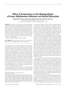
Fig. 12 Morphology of bone scaffold (sample A) before and after degradation under the flow rate of 0.025 ml/min.
The effect of shear stress on biodegradation of bone scaffold under 0.025 ml/min flow rate is shown in Fig. 12. Firstly, after the specimen was subjected to simulated body fluid, the initial shear stress occurred and located the middle pore of scaffold referred to from the level of color. Within 24 hours, the pores on the middle surface became enlarged. As the degradation time increased, the pore size also increased. The relationship between the propagation of degradation and the maximum location of fluid shear stress found in
Basri et al. / Malaysian Journal of Fundamental and Applied Sciences Special Issue on Medical Device and Technology (2017) 546-552
our study was in good agreement with previously reported experimental work on PLGA membrane [46]. Unfortunately, it is a very high cost in carrying out the scanning of the specimens using µCT. In this study, we did not carry out the immersion test for the flow rates of 0.4 and 0.8 ml/min. Various perfusion systems have been developed in an effort to enhance the development of 3D tissue constructs in vitro [47,48]. The effects of various media flow rates on cell behavior have been reported for these systems. An improved understanding of local internal shear stresses experienced by cells under flow conditions in a 3D scaffold as a function of flow rate and microarchitecture might be an aid in identifying culture conditions which would impart appropriate shear stresses as well as improve mass transport for enhanced bone cell proliferation and activity [45]. The modeling of flow through the 3D bone scaffold with complex microarchitecture and different porosity to calculate shear stresses in scaffold surface is a challenging computational problem such analyses are necessary to compare outcomes between different perfusion experiments. Computational fluid dynamics simulations that especially model scaffold microarchitecture is currently under development to directly estimate local fluid velocities and shear stress throughout perfused constructs [47].
[5]
[6]
[7]
[8]
[9]
[10]
[11]
CONCLUSION The fluid shear stress has a great effect on the surface morphology of bone scaffold. This study is helpful for understanding the influence of the fluid shear stress of the in vitro degradation process of porous magnesium scaffold. The flow rates of bone scaffolds under physiological activities have been given the impact of the biodegradation and the effect of mass transport on the in vitro degradation process should be further investigated. It is deduced that the in vivo biodegradation of bone scaffold implants under fluid shear stress should be carefully considered for the advance appropriate degradation design for matching the healing or generation process in the biodegradable medical applications. From the results and discussion above, it can be concluded as follows: 1. The wall shear stress increases as the flow rate increases. 2. The permeability increases as the porosity increases. 3. Effect wall shear stress on biodegradation has been fully developed, initial degradation refers to the location of wall shear stress. Understanding the influence of fluid shear stress on the biodegradation of porous scaffold is helpful for effective prediction of the in vivo degradation dynamics, which is important in developing appropriate biodegradable medical implants and drug delivery system made of magnesium.
[12]
[13]
[14]
[15]
[16]
[17]
[18] [19]
[20]
ACKNOWLEDGEMENT This work was part of an International Research Collaboration between Universitas Sriwijaya, Indonesia and the Universiti Teknologi Malaysia, Malaysia.
[21]
[22]
REFERENCES [1]
[2]
[3]
[4]
L. M. McNamara and P. J. Prendergast, 2007. Bone remodeling algorithms incorporating both strain and microdamage stimuli. Journal of Biomechanics 40(6), 1381–1391. C. Wittkowske, G.C. Reilly, D. Lacroix, and C.M. Perrault, 2016. In vitro bone cell models: Impact of fluid shear stress on bone formation. Frontiers in Bioengineering and Biotechnology 4(87), 1-22. A. G. Mitsak, J. M. Kemppainen, M. T. Harris, and S. J. Hollister, 2011. Effect of polycaprolactone scaffold permeability on bone regeneration in vivo. Tissue Engineering: Part A 17(13&14), 1831–1839. M. Bartnikowski, T. J. Klein, F. P. W. Melchels, and M. A. Woodruff, 2014. Effects of scaffold architecture on mechanical characteristics and osteoblast response to static and perfusion bioreactor cultures.
[23]
[24]
[25]
Biotechnology and Bioengineering 111(7), 1440–1451. V. Serpooshan, M. Julien, O. Nguyen, H. Wang, A. Li, N. Muja, J. E. Henderson, and S. N. Nazhat, 2010. Reduced hydraulic permeability of three-dimensional collagen scaffolds attenuates gel contraction and promotes the growth and differentiation of mesenchymal stem cells. Acta Biomaterialia 6(10), 3978–3987. J. M. Kemppainen and S. J. Hollister, 2010. Differential effects of designed scaffold permeability on chondrogenesis by chondrocytes and bone marrow stromal cells. Biomaterials 31(2), 279–287. W. J. Hendrikson, A. J. Deegan, Y. Yang, C. A. Van Blitterswijk, N. Verdonschot, L. Moroni, and J. Rouwkema, 2017. Influence of additive manufactured scaffold architecture on the distribution of surface strains and fluid flow shear stress and expected osteochondral cell differentiation. Frontiers in Bioengineering and Biotechnology 5(6), 1– 11. R. Voronov, S. VanGordon, V. I. Sikavitsas, and D. V. Papavassiliou, 2010. Computational modeling of flow-induced shear stresses within 3D salt-leached porous scaffolds imaged via micro-CT. Journal of Biomechanics 43(7), 1279–1286. F. J. O'Brien, B. A. Harley, M. A. Waller, I. V Yannas, L. J. Gibsond, and P. J. Prendergast, 2007. The effect of pore size on permeability and cell attachment in collagen scaffolds for tissue engineering. Technolology and Health Care 15(1), 3–17. M. R. Dias, P. R. Fernandes, J. M. Guedes, and S. J. Hollister, 2012. Permeability analysis of scaffolds for bone tissue engineering. Journal of Biomechanics 45(6) 938–944. A. Lesman, Y. Blinder, and S. Levenberg, 2010. Modeling of flowinduced shear stress applied on 3D cellular scaffolds: Implications for vascular tissue engineering. Biotechnolology and Bioengineering 105(3), 645–654. F. Zhao, T. J. Vaughan, and L. M. McNamara, 2015. Quantification of fluid shear stress in bone tissue engineering scaffolds with spherical and cubical pore architectures. Biomechanic Model Mechanobiology 15(3), 561–577. H. A. Almeida and P. J. Bártolo, 2014. Design of tissue engineering scaffolds based on hyperbolic surfaces : Structural numerical evaluation. Medical Engineering & Physics 36(8), 1033–1040. C. T. Koh, D. G. T. Strange, K. Tonsomboon, and M. L. Oyen, 2013. Failure mechanisms in fibrous scaffolds. Acta Biomaterialia 9(7), 73267334. M. R. Dias, J. M. Guedes, C. L. Flanagan, S. J. Hollister, and P.R. Fernandes, 2014. Optimization of scaffold design for bone tissue engineering: A computational and experimental study. Medical Engineering & Physics 36(4), 448-457. Q. Zhang, H. Lu, N. Kawazoe, and G. Chen, 2014. Pore size effect of collagen scaffolds on cartilage regeneration. Acta Biomaterialia 10(5), 2005-2013. F. R. Rose, L. A. Cyster, D. M. Grant, C. A. Scotchford, S. M. Howdle, and K. M. Shakesheff, 2004. In vitro assessment of cell penetration into porous hydroxyapatite scaffolds with a central aligned channel. Biomaterials 25(24), 5507-5514. V. Karageorgiou and D. Kaplan, 2005. Porosity of 3D biomaterial scaffolds and osteogenesis. Biomaterials 26, 5474-5491. S. M. Lien, L. Y. Ko, and T. A. Huang, 2009. Effect of pore size on ECM secretion and cell growth in gelatin scaffold for articular cartilage tissue engineering. Acta Biomaterialia 5(2), 670-679. C. M. Murphy, M. G. Haugh, and F. J. O'Brien, 2010. The effect of mean pore size on cell attachment, proliferation, and migration in collagen-glycosaminoglycan scaffolds for bone tissue engineering. Biomaterials 31(3), 461-466. F. M. Klenke, Y. Liu, H. Yuan, E. B. Hunziker, K. A. Siebenrock, and W. Hofstetter, 2008. Impact of pore size on the vascularization and osseointegration of ceramic bone substitutes in vivo. Journal of Biomedical Materials Research - Part A 85(3), 777-786. S. J. Hollister, C. Y. Lin, E. Saito, C. Y. Lin, R. D. Schek, J. M. Taboas, J. M. Williams, B. Partee, C. L. Flanagan, A. Diggs, E. N. Wilke, G. H. Van Lenthe, R. Mu¨ller, T. Wirtz, S. Das, S. E. Feinberg, and P. H. Krebsbach, 2005. Engineering craniofacial scaffolds. Orthod Craniofacial Res 8(3), 162-173. C. Ji, A. Khademhosseini, and F. Dehghani, 2011. Enhancing cell penetration and proliferation in chitosan hydrogels for tissue engineering applications. Biomaterials 32(36), 9719-9729. J. Zeltinger, J. K. Sherwood, D. A. Graham, R. Müeller, and L. G. Griffith, 2001. Effect of pore size and void fraction on cellular adhesion, proliferation, and matrix deposition. Tissue Engineering 7(5), 557-572. P. Danilevicius, L. Georgiadi, C. J. Pateman, F. Claeyssens, M. Chatzinikolaidou, and M. Farsari, 2015. The effect of porosity on cell ingrowth into accurately defined, laser-made, polylactide-based 3D scaffolds. Applied Surface Science 336, 2-10.
551
Basri et al. / Malaysian Journal of Fundamental and Applied Sciences Special Issue on Medical Device and Technology (2017) 546-552 [26] C. Sandino, P. Kroliczek, D. D. McErlain, and S. K. Boyd, 2014. Predicting the permeability of trabecular bone by micro-computed tomography and finite element modeling. Journal of Biomechanics 47(12), 3129–3134. [27] R. P. Widmer and S. J. Ferguson, 2013. On the interrelationship of permeability and structural parameters of vertebral trabecular bone: a parametric computational study. Computer Methods in Biomechanics and Biomedical Engineering 16(8), 908-922. [28] A. Rahbari, H. Montazerian, E. Davoodi, and S. Homayoonfar, 2016. Predicting permeability of regular tissue engineering scaffolds: scaling analysis of pore architecture, scaffold length, and fluid flow rate effects. Computer Methods in Biomechanics and Biomedical Engineering 5842, 1–11. [29] A. Syahrom, M. Rafiq A. Kadir, J. Abdullah, and A. Öchsner, 2013. Permeability studies of artificial and natural cancellous bone structures. Medical Engineering & Physics 35(6), 792-799. [30] S. Truscello, G. Kerckhofs, S. Van Bael, G. Pyka, J. Schrooten, and H. Van Oosterwyck, 2012. Prediction of permeability of regular scaffolds for skeletal tissue engineering: A combined computational and experimental study. Acta Biomaterialia 8(4), 1648-1658. [31] A. P. Md. Saad, N. Jasmawati, M. N. Harun, M. R. A. Kadir, H. Nur, H. Hermawan, and A. Syahrom, 2016. Dynamic degradation of porous magnesium under a simulated environment of human cancellous bone. Corrosion Science 112, 1-12. [32] A. P. Md. Saad, R. A. A. Rahim, M. N. Harun, H. Basri, J. Abdullah, M. R. A. Kadir, and A. Syahrom, 2017. The Influence of flowrates on the dynamic degradation behavior of porous magnesium under a simulated environment of human cancellous bone. Materials & Design 122, 268279. [33] P. J. Reynisson, M. Scali, E. Smistad, E. F. Hofstad, H. O. Leira, F. Lindseth, T. A. N. Hernes, T. Amundsen, H. Sorger, and T. Langø, 2015. Airway segmentation and centerline extraction from thoracic CT Comparison of a new method to state of the art commercialized methods. PLoS One 10(12), 1–20. [34] M. Navarro, A. Michiardi, O. Castano, and J.A. Planell, 2008. Biomaterials in orthopaedics. Journal of the Royal Society Interface 5, 1137-1158. [35] J. A. Sanz-Herrera and A. R. Boccaccini, 2011. Modelling bioactivity and degradation of bioactive glass based tissue engineering scaffolds. International Journal of Solids and Structures 48(2), 257-268. [36] P. W. Hui, P. C. Leung, and A. Sher, 1996. Fluid conductance of cancellous bone graft as a predictor for graft-host interface healing. Journal of Biomechanics 29(1), 123-132. [37] M. J. Grimm and J. L. Williams, 1997. Measurements of permeability in
552
[38]
[39]
[40]
[41]
[42]
[43]
[44]
[45]
[46]
[47]
[48]
human calcaneal trabecular bone. Journal of Biomechanics 30(7), 743745, 1997. S. S. Kohles, J. B. Roberts, M. L. Upton, C. G. Wilson, L. J. Bonassar, and A. L. Schlichting, 2001. Direct perfusion measurements of cancellous bone anisotropic permeability. Journall of Biomechanics 34(9), 1197–1202. E. A Nauman, K. E. Fong, and T. M. Keaveny, 1999. Dependence of intertrabecular permeability on flow direction and anatomic site. Annals of Biomedical Engineering 27, 517–524. G. Baroud, R. Falk, M. Crookshank, S. Sponagel, and T. Steffen, 2004. Experimental and theoretical investigation of directional permeability of human vertebral cancellous bone for cement infiltration. Journal of Biomechanics 37(2), 189–196. J. C. M. Teo and S. H. Teoh, 2012. Permeability study of vertebral cancellous bone using micro-computational fluid dynamics. Computer Methods in Biomedical Engineering 15(4), 417–423. C. G. Jeong and S. J. Hollister, 2010. Mechanical, permeability, and degradation properties of 3D designed poly (1,8 Octanediol-co-Citrate) scaffolds for soft tissue engineering. Journal of Biomedical Materials Research Part B Applied Biomaterials 93(1), 141-149. C.M. Agrawal, J.S. McKinney, D. Lanctot, and K.A. Athanasiou, 2000. Effects of fluid flow on the in vitro degradation kinetics of biodegradable scaffolds for tissue engineering. Biomaterials 21(23), 2443–2452. T. S. Karande, J. L. Ong, and C. M. Agrawal, 2004. Diffusion in musculoskeletal tissue engineering scaffolds: design issues related to porosity, permeability, architecture, and nutrient mixing. Annals of Biomedical Engineering 32(12), 1728–1743. B. Porter, R. Zauel, H. Stockman, R. Guldberg, and D. Fyhrie, 2005. 3D computational modeling of media flow through scaffolds in a perfusion bioreactor. Journal of Biomechanics 38(3), 543–549. Z. Chu, Q. Zheng, M. Guo, J. Yao, P. Xu, W Feng, Y. Hou, G. Zhou, L. Wang, X. Li, and Y. Fan, 2016. The effect of fluid shear stress on the in vitro degradation of poly(lactide-co-glycolide) acid membranes. Journal of Biomedical Materials Research Part A 104(9), 2315–2324. S. H. Cartmell, B. D. Porter, A. J. García, and R. E. Guldberg, 2003. Effects of Medium Perfusion Rate on Cell-Seeded Three-Dimensional Bone Constructs in Vitro. Tissue Engineering 9(6), 1197–1203. M. E. Gomes, V. I. Sikavitsas, E. Behravesh, R. L. Reis, and A. G. Mikos, 2003. Effect of flow perfusion on the osteogenic differentiation of bone marrow stromal cells cultured on starch-based threedimensional scaffolds. Journal Biomedical Materials Research Part A 67, 87–95.