Tamkang Journal of Science and Engineering, Vol. 5, No. 3, pp. 121-127 (2002)
121
The Microsensor Technology Using to Identify the Initiation Time of Impact Induced Elastic Waves Lung-Jieh Yang1, Tsung-Tsong Wu2 and Shung-Wen Kang1 1
Department of Mechanical and Electro-Mechanical Engineering Tamkang University Tamsui, Taiwan 251, R.O.C. E-mail:
[email protected] 2 Institute of Applied Mechanics National Taiwan University Taipei, Taiwan 106, R.O.C.
Abstract The microsensor technology was used here to identify the initiation time of an impact shock. The shock excitation caused by an impact sphere with a diameter of 4-6 minimeters could generate transient elastic waves in concrete structures. Such elastic waves with frequency above 100 kHz are the active emission sources for defect detection in the non-destructive testing (NDT) of concrete using transient elastic waves. In this paper, an impact sphere, which was packaged with a piezoresistive microsensor, was fabricated to verify this new idea. The microsensor after packaging has the maximum output voltage of 100 mV and the rise time less than 5 microsecond subjected to a sphere impact. The promising result of the initiation time experiment showed that the calibrated (short circuit) signal was left behind the microsensor signal for 40 nanoseconds. Key Words: Transient Elastic Wave, Impact Initiation, Microsensor
1. Introduction There are several kinds of ultrasonic NDT methods developed to detect the defects of concrete structures, such as ultrasonic method, acoustic emission method, and transient elastic wave method. By means of the propagation of elastic waves in solid structures, the ultrasonic transducers could sense the wave pattern, which may be distorted by surface cracks, shallow cavities, hetero-junctions, etc [1]. Basically, the ultrasonic method has the intrinsic drawbacks of severe attenuation in high frequency waves and the bad resolution in low frequency waves. On the other hand, the acoustic emission method just always works at the passive mode of sensing. It was noted that the point source/point receiver
method could actively measure the structural defects and mechanical properties by an elastic wave point source stimulated from pencil breaking, capillary breaking, and ball impact without obvious attenuation [1,2]. On the issue of identifying the cracks on a concrete surface, it usually uses the transient elastic wave method. Figure 1 is the simplified schematic drawing of the measurement. The ball impact initiates the elastic wave in concrete. It takes at least two standard ultrasonic transducers to detect the surface wave signal as well as the diffracted wave signal. By some comparisons and some algorithms of inverse computations, Wu, et al. [2] deduced the crack depth and the time origin of the transient elastic wave inversely.
122
Lung-Jieh Yang et al.
Ultrasonic transducer
Impact head
a
b
θ
α
d
Figure 1. The schematic drawing of measuring a (vertical) crack depth by transient elastic wave [2]
2. The Time Origin Issue of the Transient Elastic Wave Method
Output Voltage (V)
If the time origin of the transient elastic wave could be defined as well as the wave pattern simultaneously, the detected signal or wave pattern from the standard transducers on a concrete surface would reveal more information about the concrete specimen in the frequency domain and the phase domain. That is, direct measuring the time origin of the impact shock could simplify the inverse computation of the crack depth and improve the performance of the ultrasonic system. It also enhances the feasibility or accelerates the realization of a portable NDT system using in many in-situ measurements of civil structures. In
addition, to employ the imaging method utilized in the field of geophysics to the NDT of concrete structures, the measurement of time origin is needed. Figure 2 is a typical pattern of the surface wave generated by a hard sphere impact on a steel half space. The first peak is the P-wave, and the second one is the Rayleigh wave (or surface wave). The frequency range of these elastic waves is larger than 100 kHz. On the other hand, the impact shock usually means the tremendous inertial load. Figure 3 is the time history and FFT (fast Fourier transform) spectrum of an impact signal generated by the PCB-309-A accelerometer, which is mounted on a sphere and collided with a steel platform. The maximum load with the frequency below 50 kHz is nearly approach to 2000 g! This direct impact is harmful to the expensive, conventionally large-sized piezoelectric accelerometer and is not recommended as the proper impact source of transient elastic waves for ultrasonic NDT. Therefore, if we want to measure the time origin of the impact signal by installing certain kind of sensor into the impact sphere, the fairly large frequency bandwidth and the harsh shock endurance of the sensor are certainly required. Additionally, the impact sphere has the diameter of 4-6 minimeters, and the size of the sensor is then constrained to 3 minimeters or even smaller. Herein, this work proposed the microsensor technology to solve the issues mentioned above.
Time (micro-sec) Figure 2. A classical pattern of the surface wave generated by a hard sphere impact on the steel half space
The Microsensor Technology Using to Identify the Initiation Time of Impact Induced Elastic Waves
123
Scale
Ref Lv1 A: 0 Ref Lv1 B: 30 Ref Pos A: Cntr Ref Pos B: Top Date: 29/05/96 Time: 20:50:00 A: CH1 Time
25 V Real 5 v /div -25 V Os B: CH1 Pwr Spec X:20.864 kHz
156.8591ms Y: -39.956 dBVrms
30 dBVrms dB Mag 10 dB /-div -70 dBVrms 0 Hz
51.2 kHz
Figure 3. The time history and FFT (fast Fourier transform) spectrum of an impact signal generated by the PCB-309-A accelerometer, which is mounted on a sphere and collided with a steel platform.
3. Detection Using Piezoresistive Force Sensor For the flourishing development of the micro-electro-mechanical systems (MEMS) recently, the sensors using micromachining technology could greatly reduce the size and endeavor to have cost effectiveness, larger frequency bandwidth and harsh endurance than the conventional ones. The microsensor technology generally composes of three kinds of sensor chips. They are capacitive, piezoelectric and piezoresistive types corresponding to different working principles. The capacitive microsensor needs the delicate circuitry capability for measuring infinitesimal capacitance and for avoiding parasitic noises. Meanwhile, the piezoelectric microsensor needs coating the piezoelectric thin films, e.g., PZT or ZnO, on the sensor chips for silicon is not a piezoelectric material. Therefore, there are some processing compatibility problems during the material integration of piezoelectric microsensors. For the silicon-based micromachining techniques, the piezoresistive sensor is therefore the primary and the most well developed one so far. The piezoresistive pressures sensors and accelerometers are two successful examples and widely used
commercially for its IC and processing compatibilities [3]. The design and the fabrication methods of piezoresistive microsensors could refer to references [4, 5] Although semiconductor silicon has the strong dependence on the temperature drift correlated with piezoresistance, we still ignore this negative influence of temperature on the time origin problem herein for the ultra-short period of test time. By the mercy of the small size down to minimeter scale, the bulk-micromachined piezoresistive sensor is suitable for detecting the time-origin of the impact signal by means of elastic waves transmitting through the impact sphere to the piezoresistive sensing portion of the silicon microsensor. This argument correlates two subsequent considerations. The first one is whether the piezoresistive sensor is fast enough to pick up the elastic wave. Although the sensor’s frequency bandwidth as high as several hundreds of kHz is scarcely known, yet there’s no report that the piezoresistive effect of silicon itself could not response the impact shock on time [6]. The second consideration about the feasibility of this work is where to purchase the proper tactile force sensor with minimeter size. General speaking, micro force sensors are usually tailor-made corresponding to their
124
Lung-Jieh Yang et al.
special application environment. Although the working principles of tactile force sensors and pressure sensors are basically different, this work chose the commercial piezoresistive pressure sensor (made by SMI Corp., USA) shown in Figure 4 to be the impact force sensor with certain special package treatment for convenience. There are two procedures in this package treatment shown in Figure 5. The pressure sensor chip was cling to the printed-circuit-board (PCB) and forward to the wire bonding process first. Then the small chip module is coated with epoxy, which is very robust after solidifying, and carefully installed on the top surface of the impact sphere. A tiny ball with a diameter of 0.5mm is inserted manually between the diaphragm of the pressure sensor and the impact sphere. This treatment can reduce the filtering effect of package and avoid the bonding wires’ departure from the bonding pads by improper manipulation. Figure 6 shows the impact sphere with a microsensor during the packaging process.
Microsensor
Bonding wire
Epoxy
Tiny, in-between sphere with diameter of 0.5mm Impact sphere with diameter of 6 mm
Figure 5. The package method of a piezoresistive micro pressure sensor to the impact sphere with diameter of 6mm (The arrows on the top surface denote the bias for Wheatstone bridge of the microsensor and the output signal.)
Figure 6. The impact sphere is fastened by an X-Y stage and heated to solidify the epoxy during the packaging process.
4. Experimental and Results
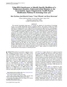
Figure 4. The top microscopic view of a commercial piezoresistive pressure sensor (SMI Corp., U. S. A.) with a chip area of 1.8 mm×1.8 mm. The four piezoresistors (circle blocks), connected as a Wheatstone bridge, are implanted on a square diaphragm (dash-line block) of this silicon pressure sensor chip.
The set-up of the impact experiment for transient elastic wave NDT is shown in Figure 7 and Figure 8. The LeCroy-9314L oscilloscope could capture the signal with the frequency up to 500 MHz, and is suitable for recording the history of the ultrasonic signals. The piezoresistive microsensor (with a configuration of Wheatstone bridge) packaged above the impact sphere was biased with 1 V and had an impact test at first. The output signal triggered by the piezoresistive microsensor has the maximum amplitude of 100 mV and the rise time less than 5 microseconds. This test demonstrated the piezoresistive microsensor is
The Microsensor Technology Using to Identify the Initiation Time of Impact Induced Elastic Waves
working when subjected to an impact load. The whole data acquisition system was triggered by a short-circuit source (channel 1 in Figure 7) rather than by the piezoresistive sensor. The short-circuit source is temporarily used as the calibration standard of the time origin of the impact sphere experiment, but is not feasible to the real application of concrete specimens. The short-circuit path in Figure 7 is from the 0.2 Volt DC source, through the impact steel half space, the impact sphere, and finally to the ground. Whether the impact sphere collides with the steel half space determines the “switch-on” state of the easy circuit. It is impossible to implement such a trigger circuit on the real application for the electrical isolation of concrete structures. Therefore, we should feedback this information of the delay time of impact initiation into the later-on, practical NDT of the concrete structures if the microsensor in the impact sphere is working. The above statement also clarifies why we spent so much effort to package a microsensor into the tiny impact sphere instead of just using the short-circuit technique. Additionally, the ultrasonic transducer on the steel-half space of Figures 7 and 8 received the transient elastic wave propagated from the impact point. The signals of the ultrasonic transducer (channel 2 in Figure
7) and the piezoresistive microsensor (channel 3 in Figure 7) shown in Figure 9 reveal directly that 27 microseconds is required for the elastic wave to travel from the impact point to the ultrasonic transducer (with the distance about 15 cm.) Then the P-wave speed is matched with the speed value of steel (5050 m/sec.) Moreover, there should be some time delay between the signals of the microsensor and the short-circuit source by the finite diameter (6 mm) of the impact sphere made of steel. In other words, the magnified plot of Figure 9, i.e. Figure 10, around the impact instant should show that the short-circuit signal goes ahead of the signal pick by microsensor for 1 microsecond or even shorter. However, it seems not the case in Figure 10. The short-circuit signal was left behind the microsensor signal for even 40 nanoseconds! Such a result, contradicted to our physical intuition, might be explained that the microsensor also has the acceleration signal output due to the finite values of the equivalent mass and stiffness of the impact sphere after packaging with the piezoresistive microsensor. In other words, there is a huge acceleration exerting on piezoresistive microsensor before the impact collision with the steel platform. LeCroy-9314L Oscilloscope
Ch1
Ch2
125
PC
Ch3 to Ch3
V0 to ground Short-circuit source (0.2 Volt)
Wheatstone bridge of the microsensor on the impact sphere
Ultrasonic transducer on the surface crack
Crack
Transient elastic wave induced by the ball-sphere impact
Figure 7. The experimental set up of detecting the initiation time of an impact excitation on a steel platform (half space)
126
Lung-Jieh Yang et al.
Figure 8. Some components of the experiment in Figure 7: including the impact sphere with a microsensor (left) and the conventional ultrasonic transducer (right) on the steel platform
Output Voltage (V)
27ms
Time History (50 µs / div. ; 10 ns / unit)
Output Voltage (V)
Figure 9. Signals pick up by the ultrasonic transducer on the surface of the steel half space, the microsensor on the impact sphere, and the short circuit source, which sets the initiation of the signal pick-up. The left arrow denotes the impact instant, and the right arrow denotes the when that the elastic wave arrives the ultrasonic transducer.
40ns
Time History (10 ns / unit)
Figure 10. The very beginning of the instant that impact sphere collides with the steel half space (the magnified section of the impact initiation in Figure 9). The right arrow denotes the impact instant, and the left arrow denotes the when that the piezoresistive microsensor senses the acceleration of the impact sphere before the impact instant.
The Microsensor Technology Using to Identify the Initiation Time of Impact Induced Elastic Waves
5. Conclusion This paper proposed the using of piezoresistive microsensors to detect the time origin of the transient elastic wave excited by an impact shock of small steel-ball. Proper package method is the most important issue in this research of microsensors or MEMS technology. The microsensor after packaging herein has the maximum output voltage of 100 mV and the rise time less than 5 microsecond subjected to a sphere impact. The promising result of the initiation time experiment showed the feasibility of this new idea, and the calibrated (short circuit) signal of the time origin was left behind the microsensor signal for 40 nanoseconds in the prototype test.
Acknowledgments The authors want to appreciate the financial support from National Science Council, Republic of China, under the contract number of NSC-87-2218-E-032-008 and acknowledge the valuable discussion with Prof. Pei-Zen Chang, the Institute of Applied Mechanics, National Taiwan University, Taiwan R.O.C.
References [1]
[2]
[3]
[4]
[5]
Wu, T.-T. and Fang, J.-S., “A New Method for Measuring Concrete Elastic Constants Using Horizontally Polarized Conical Transducers,” J. Acoust. Soc. Am., Vol. 101, pp. 330-336 (1997). Wu, T.-T., Fang, J.-S. and Liu, P.-L., “Detection of the Depth of a Surface-breaking Crack Using Transient Elastic Wave,” Journal of Acoustic Society of America, Vol. 97, pp. 1678-1686 (1995). O’Connor, “MEMS-microelectromechanical Systems,” Mechanical Engineering, pp. 40-47 (1992). Chang P.-Z. and Yang, L.-J. “A Method Using V-groove to Monitor the Thickness of Silicon Membrane with um Resolution,” Journal of Micromechanics and Microengineering, Vol. 8, pp. 180-185 (1998). Yang, L.-J., Chang, P.-Z. and Chiang, C.-C., “The Application of V-groove Slot-array Method to the Piezoresistive Pressure Sensors,” Journal of the Chinese Institute of Engineer, Vol. 20, pp. 335-341 (1997).
[6]
127
Smith, C. S., “Piezoresistance Effect in Germanium and Silicon,” Physical Review, Vol. 94, pp. 42-49 (1954).
Manuscript Received: Mar. 11, 2002 Revision Received: May 20, 2002 and Accepted: Jun. 20, 2002