The problem of upstream traffic synchronization in Passive Optical Networks Glen Kramer Department of Computer Science University of California Davis, CA 95616
[email protected]
Abstaract. Recently Passive Optical networks gained a lot of attention as a possible solution to the broadband local access network. PON may be deployed as a bus, ring, or tree topology. While it is a very cost-effective solution, it has some unique problems, not found in backbone or metropolitan networks. One of such problems is upstream traffic synchronization. In the upstream direction PON is a multipoint-to-point network. Because distance from central office to every network unit is different, if every unit will transmit in its own time slot, due to differences in propagation delays, data will collide in the point where fibers from different network units join together. In this paper we present an operation called ranging – a process of finding a specific delay for every network unit, such that all upstream transmissions will arrive to the central office without collisions. There are several ways to perform ranging. The presented solution is very cost-effective, as it doesn’t require additional optical transmitters and receivers to be installed.
Page 1 of 7
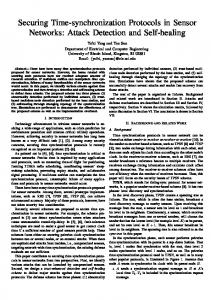
What is PON Passive Optical Network (PON) is a network with no active elements in the signals’ path from source to destination*. The only interior elements used by such networks are passive combiners, couplers, and splitters. As a result PONs always are single hop networks. Main application of PON is a local access network, the “last mile” before reaching the customer. PON may be deployed in several basic topologies: tree, bus, and ring [1]. All transmissions in a PON are performed between Optical Line Terminal (OLT) and Optical Network Units (ONU). Therefore in the downstream direction PON is a point-to-multipoint network, and in the upstream direction it is a multipoint-to-point network.
ONU1 ONU2 OLT
OLT ONU3
ONU4
ONU1
ONU5
ONU5
(a) Tree topology
ONU4 ONU2
ONU2
ONU4 ONU3
OLT
(c) Ring topology ONU1
ONU3 ONU5
(b) Bus topology
Figure 1. Various PON topologies
Because there is very little internal reflection in the passive elements of the network, PON can utilize bidirectional transmission over the same fiber on the same wavelength. Because there is no signal amplification or regeneration within the network, and there are also insertion and splitting losses, the maximum distance between OLT and ONU should be in the range 20 – 25 km. This distance depends on the signal attenuation in the PON, specifically on the number of splitters installed.
*
Sometimes, in the literature PON is defined as a network with no optical-to-electrical-to-optical conversion in the path from source to destination. This definition is not accurate, as all-optical waverouters and switches are being introduced. The network may have no OEO conversion, but still will have active elements in it.
Page 2 of 7
Description of the problem In this project we will consider TDM based PON with fixed bandwidth allocated for every ONU. In the downstream direction OLT sends 125 µs frames consisting of N timeslots. Every ONU extracts its own data by reading its associated time slot. However, as it was stated above in the upstream direction PON is a multipoint-to-point network. Because distance from OLT to every ONU is different, if every ONU will transmit in its own time slot, due to differences in propagation delays from ONUs, data frames may collide in the point where fibers from different ONUs join together. Picture below illustrates this problem.
time slot 1
time slot 2
time slot N
time slot 1
time slot 2
time slot N OLT time
1
T d 2
d 1
T
Tu
collision
time slot 1
time slot 2
time slot N
time slot 1
time slot 2 ONU1 time
T
u 2
data from ONU1
time slot 1
time slot 2
time slot N
time slot 1
time slot 2 ONU2 time
data from ONU2
Figure 2. Data collides due to difference in propagation delays. Td1 – downstream delay to ONU1, Td2 – downstream delay to ONU2, Tu1 – upstream delay from ONU1, Tu2 – upstream delay from ONU2. Generally, there is no correlation between upstream and downstream delays. The connection very often may employ different fibers for upstream and downstream flows. In this project we will make no assumptions as to what values the propagation delay may have or their relationship to each other. The goal of this project is to investigate how ONUs should be synchronized to avoid frame collisions when sending data upstream. This procedure is called ranging. Ranging is a process of measuring or calculating a specific delay for every ONU. There are two types of ranging to be performed: coarse and fine-tuning. Coarse ranging is performed as initial boot up sequence. Fine ranging should be performed constantly as the delay may change due to change of the temperature in the fiber or other factors. Without fine ranging, collisions may begin to appear after some period of normal operation.
Solution Here we present a procedure for in-band coarse ranging. Coarse ranging should be performed before an ONU is allowed to transmit data upstream. Having out-of-band ranging, say, on a different wavelength is not justifiable economically as this additional equipment will remain underutilized most of the time. Another solution was proposed in [6]. It employs low level low frequency signal and also requires separate ranging transmitters and ranging receivers.
Page 3 of 7
Below is the description of the ranging procedure that uses the same set of transmitters and receivers for data transfer and for the ranging: Step 1: After the ONU is powered on, OLT should initiate the ranging procedure. It starts with broadcasting MUTE control message. On receiving MUTE message all operational ONUs should suspend their upstream traffic. Step 2: OLT starts internal counter with frequency corresponding to the connection bit rate. For example, in OC-3 PON the counter frequency is 155.52 MHz. Step 3: OLT sends RANGE control message to the ONU being ranged. Let T0Tx be the transmission time of the RANGE message. Step 4: RANGE message will arrive to ONUi at time Tid + T0Tx, where Tid is a propagation delay from OLT to ONUi. Step 5
As soon as the RANGE message received, ONUi will send REPLY message to the OLT. Because all other ONUs have suspended their transmissions, this message won’t collide with any other transmission. Let TiTx be the transmission time of the RANGE message.
Step 6: REPLY message will arrive to OLT at time Trt = T0Tx + Tid + TiTx + Tiu, where Tiu is a propagation delay from ONUi to OLT. This time is noted by reading the value of the counter started in step 2. T RT
RANGE REPLY
u i
T
d
Ti
T 0Tx
OLT time
RANGE REPLY
ONUi time
T iTx
Figure 3. Round trip delay as measured by the OLT: Trt = T0Tx + Tid + TiTx + Tiu Step 7: As all delays are measured in terms of bits at the line’s rate, T0Tx and TiTx may be expressed as length of RANGE message and length of REPLY message respectively: T0Tx = length of RANGE message (bits) TiTx = length of REPLY message (bits). Then, roundtrip propagation delay (delay without transmission times) is Tp = Tid + Tiu = Trt - T0Tx - TiTx = Trt – length of RANGE message - length of REPLY message We assume that format of the messages and hence their lengths are known, so we can calculate the roundtrip propagation delay. OLT will calculate the delay specific for ONUi (in terms of bits at the line’s rate): Ti∆ = Bit Rate x Frame time x n – Tp where n is a minimal integer such that Ti∆ is non-negative. For example, for OC-3 rates Ti∆ = 155.52 Mbps x 125 µs x n – Tp = 19440 x n – Tp.
Page 4 of 7
Step 8: OLT sends the delay value back to ONUi (SETDELAY message) This message is being broadcast, so that all other ONUs will resume their upstream transmission when they receive this message. ONUi will store the value of Ti∆ and will apply it to all upstream transmissions as shown on figure 4. time slot N
time slot 1
time slot 2
data from ONU1
data from ONU2
time slot N OLT time
d 2
d 1
T
T
1
time slot 2
Tu
time slot 1
time slot 1
time slot 2
time slot N
time slot 1
time slot 2 ONU1 time
data from ONU1
T
u 2
T 1∆
time slot 1
time slot 2
time slot N
time slot 1
time slot 2
data from ONU2
ONU2 time
T 2∆
Figure 4. Every ONU applies a specific delay before transmitting data upstream
Fine-tuning Due to some random processes in electronic equipment and due to distributed nature of PON, packets arriving to the OLT will always have a relative jitter. Therefore, to avoid collisions (when few bits of one packet overlapped with few bits of its neighbor packet) the packets should be spaced from each other. This space is called guard band and is typically from 16 to 64 bits long. Also at the beginning of every packet should be a special pattern called preamble. Preamble serves dual function: first it allows receiver to adjust to the power of incoming signal*, and second, it allows the receiver to lock on the phase of incoming signal, thus reading correct data despite the signal jitter. Guard bands are selected such that a jitter caused by random processes should be entirely within the guard band. However, systematic shift may be caused, for example, by temperature change of the environment (day-night, or summer-winter), or some other, faster processes, like power voltage change. In this case OLT should dynamically adjust the ONUs’ delay. To do so, OLT sends a control signal to ONU with a small value δ (either positive or negative), and the ONU, in turn adjusts its delay: Ti∆ = Ti∆ + δ.
Conclusion The described above method of PON ranging was presented as a very economical solution to do autoranging. Alternatives, described in literature, are all require additional equipment to be installed [2], [3]. It is possible to do autoranging manually, or by using external mobile equipment, however the precision of those measurements will not be as accurate, because different electronic parts will be used for measuring *
As every ONU is placed at a different distance from the OLT, due to signal attenuation in the fiber, power of the signal reaching OLT will vary from ONU to ONU. This is called “near-far” problem [4]. To solve this problem adjustable attenuators may be installed in every ONU transmitter, however it will require dynamic adjustment of attenuation, and generally, more expensive then to let OLT handle signals of various levels.
Page 5 of 7
the delay and applying it. In the presented method, roundtrip delay measured by OLT also includes delay of exactly the same electronics that will be used for regular data transmission after ranging is done. The presented method of ranging has its drawbacks. The main of them is that all ONUs should suspend the upstream transmission while one ONU is being ranged. For the burst mode traffic ONUs may just buffer the data. Below is the example of calculation of the buffer size an ONU should have. Assuming an OC-3 PON and distance between OLT and ONU is 20km (one way), we get: Time all transmission should be suspended equals to round trip time (Trt), plus time to calculate a delay, plus time to send the delay to ONU. Assume RANGE, REPLY, and SETDELAY messages are 8 bytes long each. Pundtrip time Trt = T0Tx + Tid + TiTx + Tiu = = 8*8*0.0065µs + 100 µs + 8*8*0.0065µs + 100 µs ≈ 201 µs. Time to calculate the delay includes reading the counter and performing few ALU operations. This time depends on CPU used. Let’s take it to be 10 µs ( for some very slow CPU). Time to send SETDELAY message back consist of transmission time plus propagation time to the farthest ONU. Let’s take maximum distance 25 km, then sending SETDELAY takes 8*8*0.0065µs + 125µs ≤ 126µs Total time all transmissions should be suspended is 201µs + 10µs + 126µs = 337µs At OC-3 bit rate that equals to approx. 6552 bytes. For the streaming traffic, buffering is not applicable, as there will never be a gap, when ONU can flush the buffer. In most cases streaming (synchronous) traffic allows frames to be dropped. Higher level protocol would perform error checking if necessary. Also, often PON will be deployed as a dual ring or dual tree. In this case, only one side of the PON structure should be suspended at a time. Effectively, that means, that the bandwidth available to ONUs will decrease to half of its normal value for the period of ranging (≤350µs).
Page 6 of 7
References: [1]
Pesavento, G.; Kelsey, M.; “PONs for the broadband local loop”, Lightwave magazine, Communication and Optoelectronics Group, October 1999.
[2]
Killat, Ulrich, “Access to B-ISDN via PON: ATM communication in practice”, Wiley/Teubner, 1996
[3]
Van de Voorde, I.; Van der Plas, G.; Mestdagh, D.; “Novel ranging technique for an advanced optical access network”, OFC’96, San Jose, CA, USA ,25 Feb – 1 March 1996.
[4]
Mukherjee, B.; “Optical Communication Networks”, McGraw-Hill, 1997
[5]
Quale, J.A.; “Ranging on advanced PONs”, Proceedings of 13th Annual Conference on European Fibre Optic Communications and Networks, Brighton, UK, 27 – 30 June 1995.
[6]
Fellegara, A.; “Asymmetrical bidirectional system architecture for digital ranging in TDMA systems”, Electronics Letters, vol.32, (no.1), IEE, 4 Jan. 1996
Page 7 of 7