THERMAL MODELING OF A LINEAR INDUCTION MOTOR USED TO DRIVE A POWER SUPPLY SYSTEM FOR AN ELECTRIC LOCOMOTIVE Costica NITUCA1, Gabriel CHIRIAC *1, Dumitru CUCIUREANU2, Catalin DUMITRESCU1, Guoqiang ZHANG3, Dong HAN3, Adrian PLESCA1 “Gheorghe Asachi” Technical University of Iasi, Faculty of Electrical Engineering, Iasi, Romania
*1
“Q” SRL, Iasi, Romania
2
3
Institute of Electrical Engineering, Chinese Academy of Sciences, Beijing, China *
Corresponding author; E-mail:
[email protected]
In this article a thermal modeling is developed for a double sided linear induction motor which is used to drive a power supply system for an electric locomotive. Two cases were considered for the linear motor, with full plate armature and with sectioned plate armature. The thermal model has been obtained with Pro/Engineering software package and the mesh of the 3D thermal model has been done using tetrahedron solid elements types. Experimental validation of the model has been realized too. Errors between the simulations and the experimental data (between 1% and 4%) show that the proposed model can be used for accurate precision of the heat distribution on the linear motor. Key words: linear induction motor, thermal regime, modeling, simulations, experimental validation 1. Introduction Linear motors can be used as efficient tool to achieve the high speed and precision for linear motion applications or for different systems where they can replace the rotary electric machines, hydraulic or pneumatic equipments with linear movement. Linear motors are used in automotive suspension [1], wave-energy conversion [2], electrical transport, elevators in high buildings [3, 4] or sliding door applications [5]. Ultra-precision applications are also a domain utilization for the linear motors [6]. Interaction between electromagnetic and temperature field in a solid ferromagnetic plate is considered in [7] by moving linear high frequency induction heater. Another possible application of the linear induction motor is to drive the pantograph collecting system on the electric vehicles, like electric locomotives and tramways [8] where the linear motor assures the contact force between the catenary and the pantograph’s skate. Thus, a better contact improves the current collection process and reduces the wear of the pantograph and of the contact line and reduces the detachments of the pantograph skate from the wire [9]. In this case the motor operates in an oscillating regime which can generate heat problems and it can affect the thermal deformation of the machine structure. The thermal deformation characteristics can be identified through measuring the thermal error caused from thermal deformation of the linear scale and the machine structure [10].
1
The thermal regime depends on the supply system characteristics, on the driven kinematics, as well as on the linear motor structure and on its cooling system. The need for an analysis of the thermal processes can arise when designing a linear motor [11] but also for the supplying system and for the protection of the system [12]. The possibility of reducing the nonlinearities of the model for calculating the thermal characteristics of a linear asynchronous machine is considered. The temperature field is calculated in the time domain taking into account the change in the thermal and electromagnetic properties of the material at each time step [13]. Finite Element Method can be used to analyze the heat transfer into the linear motors [14]. The thermal transfer aspects are criteria in choosing a right linear motor for a specific application considering the heat transfer by conduction, radiation and convection, the heating sources and the duty cycle of the motor [15]. Is considered the thermal characteristics of a linear induction machine under intensive track operation. Thermal characteristics are calculated using the method of detailed equivalent heat circuit. A brief analysis of the possibility of operation in different operating modes is given [16]. It should be noted that for a double-sided linear motor with yoke and multi-segmented array, the coating on the coil cannot withstand the temperature more than 120 ℃ [17]. The surface area joining the linear motor coil to the application carriage is large so it will be inaccurate to assume a constant temperature over the entire surface. The temperature of the surface is different for different location and time [18]. A three-dimensional finite difference method is adopted to model the motor coil to calculate the amount of the heat transferred to the carriage. The theoretical results are verified with experiments. It is demonstrated that the proposed model is capable to predict accurately the temperature variation at the interface between the motor coil and carriage, and therefore the heat flux can be obtained for the full range of the motor operating power [19]. Starting from the above considerations this paper presents thermal analysis (modeling and experimental) of a linear induction motor. The test bench uses a linear induction motor to drive an asymmetrical pantograph with the aim to supply an electric locomotive. The contact force of the pantograph is assured by the linear motor and the system has to operate for a long time, even hours, (the electric locomotives have a long operating time) and thus it becomes very important to study the thermal regime of the motor. The objectives of this work are: – To develop a thermal model for the linear induction motor; – Two cases are considered for the thermal model and simulations: with full plate armature and with sectioned plate armature; – Simulations are realized using the Pro/Engineering software package; – Experimental tests are also realized for the both cases in order to validate the thermal model; – Comparison of the simulated and experimental data are considered to estimate if the proposed model can be used for accurate predictions of the temperature distribution into the motor. 2. The linear induction motor The linear induction motor is used on a test bench which simulates the power supply for an electric locomotive (Fig. 1). The linear induction motor (1) is used to drive an asymmetrical pantograph (3) necessary for the power collecting from a contact wire (4). The contact wire is realized as a rotating copper disc. The pantograph has to act with a contact force Fc on the contact line. The contact force is given by a resort (the main force FR) and by the linear induction motor (for a 2
supplementary force FLIM). Thus, the motor offers the possibility to control the contact force according to the power collecting necessity. The motor operates in oscillating regime and because of this special regime the thermal aspects become important.
Figure 1. Test bench. (1) linear induction motor; (2) inductor; (3) asymmetrical pantograph; (4) copper rotating disk. The linear motor is a three-phase asynchronous machine with a plate mobile armature (1) from copper (Fig. 2). The motor has a bilateral structure, having two inductors, 2a and 2b, (a double sided linear motor) with the ring windings in 24 slots, yielding the coils (3). The mobile plate armature is vertically placed and it has an oscillating movement (4) on a distance of about 60..90 mm and an air gap δ = 4 mm. It is important to notice that some special effects of the linear motors (the edge effects, the transversal effects) are neglected, in order to simplify the thermal model. The main restrictive effect for the motor power is the heat transfer and thus, the thermal behavior must be taken into account. For the small oscillating movements (less than 60..90 mm), the armature plate will be usually in the same relative position with respect to the inductors, which will give a higher heating and consequently an important influence over the machine’s parameters and operating. The motor is not a homogeneous body but it is a combination of different materials (cooper, steel, iron, etc.), and the heating analysis could be complex.
Figure 2. Bilateral linear induction motor. (1) plate mobile armature; (2a), (2b) inductors of the double sided linear motor; (3) coils; (4) oscillating movement of the plate mobile armature. 3. The heating differential equation for the linear motor The linear motors are different to study from the thermal point of view in comparison with the classical rotary motors due to their specific construction and the electromagnetic aspects. Rotary 3
induction motors are largely used and there is a high interest in their analysis, including the thermal aspects [20, 21]. Overheating can cause undesirable motor failures with high cost due to the interruption and damages on equipments. Inside the motor the stator insulation may degrade because of the overheating and, even if the temperature doesn’t exceed the motor insulation class limit, it will decrease the lifetime of the insulation. Venkatamaran [22] states that an operating temperature increase of 10°C in excess of the thermal limit cuts the life of stator insulation by half. The plate armature can be deformed due to the overheating and this deformation could lead to undesirable contacts between the plate and the inductors. An analysis can be made, for a first estimation, in analogy with the rotary machines starting from the thermal equation:
Qdt Adt Cd
(1)
The heat Q released into the motor in a time dt is equal to the heat released by the machine for a difference of temperature θ between the machine and the environment (Aθdt), plus the heat absorbed by the machine (Cdθ) to increase its temperature by θ degrees. This equation can be rewritten as:
dt
Cd Q A
(2)
where: - C is the thermal capacity of the machine; - A is the heat transfer capacity of the machine. The integration of the eq. (2) will give the variation relationship of the machine heating:
Q 1 exp(t / (C / A)) 0 exp(t / (C / A)) A
(3)
where θ0 is the initial temperature of the machine. The ratio C/A is a constant for a given machine and represents the time constant of the machine heating or the temperature delay (thermal inertia) of the machine: T
C A
(4)
For the actual linear motor this constant was estimated [23, 24] for two different plate armatures, a full plate armature and a sectioned plate armature. Thus it was calculated the maximum temperature into the motor and compared with the measurements, resulting the values of 92 ℃ and respective 96 ℃. These differences are due to the different plate armatures. The sectioned plate armature has a low surface area to eliminate the heat, resulting in higher temperatures on the motor. 4
A thermal study could also start from the power balance equation for each volume element dV,
PC PT PR PA
(5)
The left term of the eq. 5 is the heating power from the current flow, PC. On the right-hand side of the eq. 5 there are three powers: PT, as the heat stored by temporal change of temperature, PR, as the power removed from the element by thermal conduction and PA, as the thermal power dissipated to the environment area by the surface area. The above equation can be expressed as follow, considering the four powers:
l j dV c t dV div grad dV k S dV 2
a
(6)
The material density, specific heat and thermal conductivity do not have an important temperature variation and, into a simplified model, they can be considered as constants. The electrical resistivity has an important temperature variation and it can be estimated through a linear variation:
0 1 0
(7)
It results a nonlinear and nonhomogeneous equation which can be resolved by numerical methods:
0 1
i2 dV S2
c t dV div grad dV k S dV l
(8)
Using the finite element method it can be estimated the thermal variation within the linear induction motor by 3D simulation.
4. Thermal modeling of the double sided linear induction motor To study the thermal aspects of the considered linear induction motor it was developed a thermal model and simulations were also realized. It was developed a geometrical model of the linear induction motor with the plate armature of copper and the two inductors symmetrically placed over the plate armature. The setting parameters used for the thermal simulations are presented in Tab 1. Tab. 1. Setting parameters used for the thermal simulation Mobile plate armature (copper) Thermal conductivity [Wm–1K–1] Specific heat [Jkg–1K–1] Material density [kgm–3]
385 385 8900 5
Yokes (iron)
Insulation
420.27 52.028 7190
1.25 137 1400
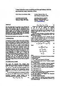
The room temperature was considered as 21℃. The simulations were realized for two cases: first, for a linear induction motor with full plate armature, and second, for a linear induction motor with sectioned plate armature. The thermal model has been obtained using the software package Pro/Engineering and all the thermal simulations have been performed with the Pro/Mechanica software package. The heat load has been applied uniformly in all the volume of every copper winding. The convection conditions have been used as boundary conditions. Also, a bulk temperature of 21ºC has been considered. The mesh of this 3D thermal model has been done using tetrahedron solids element types with the following allowable angle limits (degrees): maximum edge: 175; minimum edge: 5; maximum face: 175; minimum face: 5. The maximum aspect ratio was 30 and the maximum edge turn (degrees): 95. Also, the geometry tolerance had the following values: minimum edge length: 0.0001; minimum surface dimension: 0.0001; minimum cusp angle: 0.86; merge tolerance: 0.0001. The single pass adaptive convergence method to solve the thermal steady-state simulation has been used. Figure 3 presents the result simulation of thermal distribution into the linear induction motor. The maximum temperature is in the middle of the two inductors and it is about 92.4℃, very close to the experimental measurements. The temperatures are decreasing from about 90℃ in the middle on the copper windings, to about 60℃ into the lateral windings. On the armature plate the distribution of the temperatures is from about 85℃ in the middle to about 30℃ on the edges.
Figure 3. Distribution of the temperature over the linear induction motor
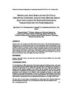
The thermal load was not distributed uniformly in all the volume of every copper winding. On the lateral areas the temperature is lower because the windings are in contact with the lateral pieces of aluminum, which have a coefficient of convection of 19.75 [Wm–1K–1]. For the inductor the coefficient is 14.2 [Wm–1K–1] and for the isolation it was considered 12.5 [Wm–1K–1]. A thermal model of the linear induction motor with sectioned plate armature was also made in order to estimate the heating areas into the motor (Fig. 4). The plate armature is vertical cutting-up sectioned and it was tested in order to reduce the eddy currents into the plate armature, which are not useful for the force developed by the linear motor. It is to mention that the plate armature is considered as acting with a constant force. The thermal distribution over the linear motor is presented in Fig. 4, with an ambient temperature of 20℃. The temperature distribution shows a maximum value in the middle of the inductors, with about 96℃, close to the experimental maximum data of about 90℃. At the edges of the inductors the temperatures decrease at about 56℃, where the heat can be release easily to the ambient medium. Into the plate armature, the temperature varies from about 96℃ inside the inductors space, to less than 30℃ outside the inductors. 6
Figure 4. Distribution of the temperature over the linear induction motor with a sectioned plate armature
5. Experimental validation of the thermal model of the linear induction motor The estimation of the temperature increase of the windings and of the other parts of the motor is made with a locked armature. The inductor is supplied at rated voltage and rated frequency from a three-phase symmetrical supply system (by a three-phase autotransformer). The measurements are on the inductor denoted (2b) because it heats up more intensely then the inductor (2a) (about 2-3%) due to the constructive imperfection of the motor. The estimation of the temperature increase of the windings and of the other parts of the motor is made with a locked armature and for a force of 70 N. There is no cooling system considered. The temperatures have been measured using an infrared camera type FLIR E40. The temperature measurement points on the linear motor are presented in Fig. 5. For the coils the temperature is measured for the slots θ1, θ3, θ6, θ10, θ12, θ13, θ15, θ19, θ22 and θ24 (ten points of measurements). All of these will give a large view over the variation of the temperature in the motor.
Figure 5. Measured points of the temperature on the inductor
Figure 6 shows the simulated and measured temperatures for the motor with full plate armature. It is to observe from the experimental data (Tab. 2, Fig. 6,) that the maximum temperature is measured in the middle of the inductor area, for the slot 13, a little higher than for the slot 12 because of the constructive imperfections of the motor. These temperatures don’t exceed the maximum temperature allowance, of 120℃.
7
100 95
Temperature [ C]
90 85 80 75 70 65 60 Simulation
55
Measured
50 0
2
4
6
8
10
12
14
16
18
20
22
24
Slot
Figure 6. Simulated and measured temperatures distribution over the inductor Tab. 2. Simulated temperatures, measured temperatures and errors for the motor with the full plate armature Simulated temperatures Measured temperatures Error Slot No [℃] [℃] [%] 1
59
60.3
2.16
3 6 10 12 13 15 19 22 24
63 69 86 92.4 92.4 86 69 63 59
64.1 69.8 87.2 93.7 94.6 88.2 70.9 64.7 61.1
1.72 1.15 1.38 1.39 2.33 2.49 2.68 2.63 3.44
Figure 7 shows the simulated and measured temperatures for the motor with sectioned plate armature. The maximum measured temperatures are also on the middle of the inductors, and the values are higher, to about 100℃. In both cases the measured temperatures are higher than the simulated ones (Tab. 2, Tab. 3). This could be explaining by neglecting the special effects of the linear motor in order to simplify the thermal model and also by the constructive imperfection of the motor. The errors presented into the Tab. 2 and Tab. 3 are still into the acceptable values.
8
100 95
Temperature [C]
90 85 80 75 70 Simulation
65
Measured 60 0
2
4
6
8
10
12
14
16
18
20
22
24
Slot
Figure 7. Simulated and measured temperatures distribution over the inductor with the sectioned plate armature Tab. 3. Simulated temperatures, measured temperatures and errors for the motor with sectioned plate armature Simulated temperatures Measured temperatures Error Slot No. [℃] [℃] [%] 1
66.1
68.3
3.22
3 6 10 12 13 15
69.4 76.3 90.2 96.1 96.1 90.2
70.2 78.8 93.2 99.4 99.8 93.6
1.14 3.17 3.22 3.32 3.71 3.63
19 22
76.3 69.4
79.3 70.9
3.78 2.12
24
66.1
68.8
3.92
6. Conclusions In this article it is studied a thermal model for a linear induction motor used to drive a pantograph from a power supply system of an electric locomotive. The drive system is subject of a patent with the number RO 128199 B1/2018. – A thermal model of the motor was developed for two cases: with full plate armature and with sectioned plate armature in order to have a thermal image of the linear induction motor and a prediction of thermal distribution. – The thermal model has been realized with Pro/Engineering software package. – Experimental tests were also realized for the both cases, the errors between the simulations and experimental data being between about 1% and 4%, which shows that the proposed model can 9
be used for accurate predictions of the temperature and heat distribution of the motor. – The maximum temperature allowance (of 120℃), is not exceeded and the motor can operate for a long time corresponding to the electric locomotive operating conditions.
Nomenclature A - Heat transfer capacity of the machine [JK–1s–1]; C - Thermal capacity of the machine [JK–1]; c – Specific heat [Jkg–1K–1]; i – Electric current [A]; j – Current density [Acm–2]; k – Total transfer coefficient; l – Perimeter of the external surface [m], PA - Thermal power dissipated to the environment area by the surface convection [W]; PC - Heating power from the current flow [W]; PR - Power removed from the element by thermal conduction [W]; PT - Heat stored by temporal change of temperature [W]; Q - Heat released into the motor in a time dt [J]; S – Surface area [m2]; Tθ –Time constant of the machine heating [s]; α – Coefficient of electrical resistivity variation with temperature; γ – Material density [kgm–3]; λ – Thermal conductivity [Wm–1K–1]; ρ – Electrical resistivity [m]; ρ0 – Electrical resistivity at the θ0 temperature [m]; θ – Temperature [℃]; θ0 –Initial temperature of the machine [℃]; θa – Environment temperature [℃]; a (as a notation) [℃].
10
References [1] Hyniova, K., et al., Experiments on energy management in active suspension of vehicles, Int. J. of Systems Applications, Engineering & Development, 6 (2012), 2, pp. 196-203 [2] Danson, M.J., Cronje, W. A., Design of a double-sided tubular permanent-magnet linear synchronous generator for wave-energy conversion, The Int. J. for Computation and Mathematics in Electrical and Electronic Engineering, Emerald Group Pub. Ltd, 27 (2008), 1, pp. 154-169 [3] Lim, H.S., et al., Design and control of a linear propulsion system for an elevator using linear switched reluctance motor drives, IEEE Trans. Ind. Electron., 55 (2008), 2, pp. 534–542 [4] Onat, A., et al., Design and implementation of a linear motor for multi-car elevators, IEEE/ASME Transactions on, 15 (2010), 5, pp. 685-693 [5] Jiménez, J. et al., Coupled electromagnetic and thermal design of miniaturized permanent magnet linear motors for sliding door applications, Int. Rev. Electr. Eng., 8 (2013), 5, pp. 1416-1426 [6] Li, L. Y., et al., “Analysis and optimization of air-core permanent magnet linear synchronous motors with overlapping concentrated windings for ultra-precision applications, Proc. 15th Int. Conf. on Electrical Machines and Systems (ICEMS), Sapporo, 2012, pp. 1-6 [7] Milošević-Mitić, V., et al.,. Dynamic temperature field in the ferromagnetic plate induced by moving high frequency inductor. Thermal Science, 18(suppl. 1) (2014), pp. 49-58 [8] Nituca, C., et al., “Pantograph drived with a linear induction motor controlled with adaptive fuzzy control, Proceedings of the 4th Int. Conf. on Electromechanical and power systems SIELMEN 2003, Chişinău, Rep. Moldova, 2003, Vol. III, pp. 55-58 [9] Nituca, C., et al., “Constructive and experimental aspects regarding the electric power collecting for very high speed train, 6th Int. Conf. on Electromechanical and Power Systems SIELMEN 2007, Analele Univ. din Craiova, 31, (2007), II, pp. 290-293. [10] J.J. Kim et al., “Thermal behavior of a machine tool equipped with linear motors, Int. J. of Machine Tools and Manufacture, 44, (2004), 7–8, pp. 749–758 [11] Sarapulov, F. N., Goman, V. V., Development of mathematical models of thermal processes in linear asynchronous motors, Russian Electrical Engineering, , 80 (2009), 8, pp. 431–435 Allerton Press, Inc., 2009. Original Russian Text, published in Elektrotekhnika, Sarapulov, F.N., Goman, V.V., 8 (2009), 8, pp. 17–21 [12] Plesca, A., Thermal analysis of fuses and busbar connections at different type of load variations, Int. Rev. on Modelling and Simulations (IREMOS), 3 (2010), 5, Part B, pp.1077-1086 [13] Tarchutkin, N. V., et al., Modeling of thermal operating modes of a linear electrical machine in a strong coupled task. Young Researchers in Electrical and Electronic Engineering (EIConRus), 2018 IEEE Conference of Russian, (2018), pp. 819-821 [14] De-Shau, H., et al., Three-Phase Linear Motor Heat Transfer Analysis Using the FiniteElement Method, Journal Heat Transfer Engineering, 31 (2010), 7, pp. 617-624
11
[15] Chevailler, S, Comparative study and selection criteria of linear motors, Ph.D. Thesis, Ecole Polytechnique Fédérale de Lausanne, Switzerland, 2006 [16] Sarapulov, F., et al. Dynamic study of thermal characteristics of linear induction motors. Electrical Machines, Drives and Power Systems (ELMA), 15th Int. Conf.on , (2017), pp. 414-418. [17] Lee, M.G., et al., Design of high precision linear stage with double-sided multi-segmented trapezoidal magnet array and its compensations for force ripples, Mechatronics, 16 (2006), pp. 331–340 [18] Chow, J.H., et al., Investigation of thermal effect in permanent magnet linear motor stage, Proceedings 11th Int. Conf. on Control, Automation, Robotics and Vision, ICARCV 2010, Singapore, 2010, pp. 258-262 [19] Chow, J.H., et al., A finite-difference thermal model of a three-phase coreless linear motor as a heat source, Applied Thermal Engineering, 87 (2015) [20] Ying, X. , Wang Y., 3D temperature field analysis of the induction motors with broken bar fault, Applied Thermal Engineering, 66 (2014), 1–2, pp. 25–34 [21] Nair, D.G., Arkkio, A. , Inverse Thermal Modelling to Determine Power Losses in Induction Motor, IEEE Transactions on Magnetics, PP (2017), 99 [22] Venkataraman, B., et al., Fundamentals of a Motor Thermal Model and its Applications in Motor Protection, Proceedings of58th Annual Conf. for Protective Relay Engineers, April 2005, pp. 127-144 [23] Nituca, C., Thermal analysis for a double sided linear induction motor, European Scientific Journal, 9 (2013), 9, pp. 38-50 [24] Chiriac, G., Thermal analysis for a bilateral linear induction motor with sectioned plate armature, European Scientific Journal, 9 (2013), 9, pp. 45-56
12