Towards a Technique for Reverse Engineering Web Transactions from a User’s Perspective Damiano Distante Dept. of Innovation Engineering University of Lecce, Italy
Tauhida Parveen Dept. of Computer Sciences Florida Institute of Technology
Scott Tilley Dept. of Computer Sciences Florida Institute of Technology
[email protected]
[email protected]
[email protected]
Abstract Many Web sites could improve their users’ experience through systematic analysis of transaction paths, so that users’ expectations and site design are more closely aligned. This paper outlines preliminary steps towards a technique for reverse engineering Web transactions from a user’s perspective. The result of the reverse engineering activity is a conceptual model that is based on extensions to the transaction design portion of the Ubiquitous Web Applications (UWA) framework. In particular, changes to the definition of an “activity,” redefinitions of the “PropertySet” associated with an activity, and refinements to the UWA Organization and Execution models are proposed. Keywords: conceptual modeling, reverse engineering, transactions, Web site evolution, Web services
This paper presents preliminary steps towards a reverse modeling technique for analyzing Web application transaction design and implementation. The proposed approach works at a conceptual level and therefore is independent of the technologies used to implement the application. The goal is to evaluate the recovered model according to its resemblance to the users’ experience, and possibly to suggest restructuring enhancements that would produce a Web site that was more effective, more maintainable, and more usable. The next section of the paper discusses Web transactions. Section 3 details salient features of the UWA transaction design model. Section 4 discusses the proposed reverse engineering technique for recovering transaction models from existing Web sites. Finally, Section 5 summarizes the paper and outlines possible avenues of further work.
1. Introduction
2. Web transactions
The Web is rapidly becoming the meta-platform of choice for developing complex transaction-intensive applications. In this context, a transaction can be defined as a sequence of activities that enables the user to reach their goal or to perform a specific task. Many such Web sites that are already deployed could improve their users’ experience through systematic analysis of actual transaction paths, so that users’ expectations and site design are more closely aligned. Such analysis can be achieved through reverse engineering. Reverse engineering is a semi-automated application analysis technique that supports program comprehension without altering the subject system. The efficacy of reverse engineering depends in part on the experience of the analyst and their application domain knowledge. The information gained through reverse engineering can substantially help the evolution of large-scale Web sites.
As the Web has matured, the nature of Web-based applications (or applications which exploit the Internet as communication media and/or use a browser as a platformneutral user interface) has changed considerably. These changes have in turn increased the importance of a systematic design methodology for the most complex of today’s Web sites. Existing hypermedia design methodologies can provide a starting point for the construction of such Web sites, but these methods usually fall short in addressing the design requirements of multifaceted transactions.
2.1. Classifying Web sites The classification system presented in [29] provides a useful organizational structure for discussing the different types of Web sites according to their level of complexity, interactivity, and functionality. Class 1 Web sites are
Proceedings of the 12th IEEE International Workshop on Program Comprehension (IWPC’04) 1092-8138/04 $ 20.00 © 2004 IEEE
those that are mostly static, providing limited functionality with no user interactivity. These are also known as “brochure-ware,” since their goal is primarily to deliver information to the user. Class 1 Web sites are the easiest of the three classes of Web sites to design, develop, and maintain. Class 2 Web sites are those that provide client-side interaction, possibly though the use of multimedia technologies such as Dynamic HTML [12] or Macromedia Flash [20]. Class 2 sites are more functionality advanced than Class 1 Web sites. They are more complicated to design due to the need to incorporate user interactions. They are also more difficult to develop and maintain, due to the presence of embedded scripts and active components that provide the interaction. Class 3 is the most complex of the three types of Web sites. They provide all the capabilities of Class 1 and Class 2 Web sites, plus the additional functionality of dynamic content supplied by a server-side database. Class 3 sites are the most complicated ones to design, develop, and deploy. As such, modeling Web transactions in this context requires significantly more expertise, and correspondingly more powerful tools. In fact, most modern Web applications build upon the infrastructure of a Class 3 Web site to provide a catalog of Web services in a business-to-business or business-toconsumer context [10]. The classification system can be extended to capture the unique characteristics of such “Class 4” Web sites, which provide a distributed information system infrastructure as the base platform for new application development. The goal of the resultant application is to execute a prescribed business process according to a design that facilitates transactions from the user’s perspective.
2.2. Hypermedia design methodologies Two factors that can influence the quality of a Web site are the use of solid design principles and the adoption of design validation practices. This realization is one of the reasons behind the creation of several hypermedia design methodologies that have been proposed in the literature. For example, WebML [26], HDM [17], and OOHDM [5]. The addition of services to a Class 4 Web site raises issues usually faced only at an implementation level, even though a well-structured and reliable design methodology becomes even more important [16]. In particular, the emergence of transactions as a central design concern poses special challenges. For the purpose of Class 4 Web sites, a transaction is defined as the sequence of activities
the user has to fulfill using the application to accomplish a particular task or to reach a particular goal.1 It is unfortunate that Class 4 Web sites are often implemented before they are designed. It is quite common that Web application transactions are simply emulated as a sequence of navigational steps through the pages of the application. This means that the user activity corresponding to each step of the transaction is represented as a navigational object. Even if this is a desirable solution for modeling Web transactions, problems arise due to the substantial differences among the user’s perspective, the site’s navigational structure, and its operational semantics. This neglect can raise longterm design issues and usability problems in the final product [10]. Most earlier hypermedia design methodologies provide only limited treatment of transactions, usually as a by-product of the Web application implementation, in particular as a realization of conceptual and navigation design artifacts. Fortunately, some of these methodologies have recently been enhanced to explicitly address transaction design. For example, the Object-Oriented Hypermedia Design Model (OOHDM) [10], the Web Site Design Method (WSDM) [23], the Araneus Design Model (ADM) [25], the OO-H technique [21], and UWE [15][22]. However, the formalism that provides the most promising support for transaction design is the Ubiquitous Web Applications (UWA) framework [36].
2.3. The UWA design framework Although the Unified Modeling Language (UML) [24][8] is commonly used for constructing traditional software applications, Web sites and Web applications are rarely designed using it. There are proposed guidelines for the use of UML to model Web applications [3], but the approach is not widely adopted by practitioners, in part because they are not able to effectively model the detailed characteristics of complex Web applications. The UWA is one of the few frameworks that provide a complete design methodology for Class 4 Web sites and Web applications that are multi-channel, multi-user and generally context-aware. Using UWA can help designers in managing complex Web application by improving communication both within the design team and with external clients. The UWA framework encourages designers to create better-organized design documentation so that future maintenance is made easier. This in turn promotes asset reuse through design independence, since 1
Transactions as described here have also been referred to as “business processes” by other authors. See for example [10][23][22].
Proceedings of the 12th IEEE International Workshop on Program Comprehension (IWPC’04) 1092-8138/04 $ 20.00 © 2004 IEEE
different portions of the design can be modified without necessarily affecting other parts. The UWA design framework organizes the process of designing a Web application into four main activities [36][30]: 1) Requirements Elicitation [32]: This phase is intended to define the stakeholders of the application, their goals, and derive application requirements through an iterative refinement process. This activity relies upon lessons learned in requirements engineering of traditional software systems. 2) Hypermedia Design and Operation Design [33]: This activity builds upon results first defined in the W2000 methodology [16]. The activity deals with defining the following four design models: Information model: structuring the contents of the application and their organization in terms of access structures; Navigation model: defining the atomic units of information (nodes) that will be delivered to the user, and how they are organized into contexts; Publishing model: defining how the application will be organized into user-accessible pages; Operation model: defining system operations and operations available to the user. 3) Transaction Design [34]: This design phase defines user activities, system transactions, and how operations are defined over them. 4) Customization Design [35]: This design phase supports ubiquity of the Web application by defining customization rules to be applied in order to adapt the application to different user profiles, access devices, and usage contexts. Breaking the design of Web applications into several activities and multiple steps in such a manner does not add complexity to the design task (as it may appear to), because it helps in obtaining a separation of concerns and has many known advantages. Among the design activities composing the UWA framework, Hypermedia and Operation Design activities may be considered to be “typical” of Web applications design. However, Requirements Elicitation, Transaction Design, and Customization Design are new activities; their definition and integration with the W2000 methodology is one of the main contributions of UWA. Using the concepts provided by the four UWA design models (and their corresponding notation), a designer can craft the application schema (a description of what the application will be—not how it will be implemented). The application schema should take into consideration the overall application requirements, including both typical business requirements and future migration paths. For
each design activity, schemas can be specified at two levels of depth and precision: (1) in-the-large, to describe general aspects (sometimes informally), without many details; and (2) and in-the-small, to describe selected aspects in more detail.
3. The UWA transaction model The proposed technique for reverse engineering Web transactions from a users’ perspective relies upon extensions to the UWA transaction model.2 In a UWAbased project, Class 4 Web application transactions (in the following equivalently referred as user activities) are basically designed by means of two models: the Organization model and the Execution model [36].
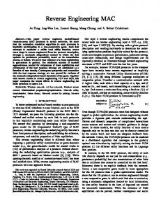
3.1. The Organization model The Organization model describes an activity from a static point of view, modeling the hierarchical organization in terms of sub-activities in which the activity can be conceptually decomposed. It also describes the relations among these sub-activities and the PropertySet of each of them. The Organization model is a particular type of UML class diagram, in which sub-activities are arranged to form a tree; the main activity corresponds to the root of the tree, while sub-activities are intermediate nodes and its leaves. An example of an Organization model for a hypothetical hotel reservation system is shown in Figure 1 [34]. The PropertySet is a set of properties (Isolation, Atomicity, Durability and Consistency (ACID)) supported by activity. It is specified with letters using stereotypes in the class diagram. Semantics associated with the PropertySet are well known in the literature of database theory [7]. Hierarchical relations (referred to as associations) between sub-activities and the main activity are shown with labels on tree branches of the Organization model. Their value, such as Required, Vital_visible, etc., describes if the execution of a subactivity is required or optional in order to complete the main activity, or if changes on data due to a sub-activity are visible by others activities or not.
2
Readers already familiar with the UWA transaction model may skip directly to Section 4.
Proceedings of the 12th IEEE International Workshop on Program Comprehension (IWPC’04) 1092-8138/04 $ 20.00 © 2004 IEEE
Figure 1: An Organization model for a possible activity of “Hotel Reservation” in a hotel Web site For each activity, the OperationSet is specified. This represents the set of elementary operations that can be invoked during the execution of the activity. Some of these operations are obligatory and some are optional. The OperationSet can be divided into subsets, the subset of the operations that are functional to the management of the activity named ManagementSet, and the subset of operations that are intended to implement the logic of the activity itself, named FunctionalSet. Examples of operations belonging to the ManagementSet are begin, begin_inv_sub, begin_inv_vital_sub, begin_vis_sub, begin_vis_vital_sub, abort, commit, end, delegate. Examples of operations belonging to the FunctionalSet are update, submit and search. The semantics associated with each of them, as derived from their name, is based in database theory.
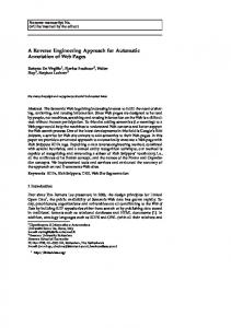
3.2. The Execution model The Execution model of an activity defines the possible execution flow among its sub-activities. It is a customized version of the UML Activity Diagram [14], usually adopted by the software engineering community to describe behavioral aspects of a system. Activities and sub-activities are represented by states (ovals), and execution flow between them is represented by state transition (arcs). Figure 2 shows an example of an Execution model for a hypothetical hotel reservation activity. It shows the
Figure 2: An Execution model for a possible activity of “Hotel Reservation” in a hotel Web site temporal order of execution of the transaction subactivities and corresponding state transitions of the system.
3.3. Simplifying the transaction model Several aspects of UWA transaction design model make it one of the most advanced and rigorous models available for designing Class 4 web sites. However, in this model, user-, system-, and data-centered requirements are considered equally. In order to fulfill our goal and obtain a model that focuses on the user’s perception of the application, we deemphasize the system and data requirements portion. Moreover, we decided to renounce most of the rigorous formalism used in the UWA in order to foster the technique’s adoption according to our purposes. The next section of the paper talks about the reviews and changes that we propose to introduce to the UWA transaction model and describes the reverse engineering technique that can be used model transactions in a legacy Web application.
4. The reverse modeling technique In principle, any design methodology can be applied in reverse mode to recover important information about legacy applications. Reverse engineering is a process of analysis, not a process of change [2]. It relies on
Proceedings of the 12th IEEE International Workshop on Program Comprehension (IWPC’04) 1092-8138/04 $ 20.00 © 2004 IEEE
compilation technologies such as parsing and data flow analysis to recreate abstract representations of the subject system. In the absence of original program documentation, the recreated abstractions serve as proxy system documentation for use by the software engineer and/or the Web designer. The quality and efficiency of Class 4 sites can benefit by designing transactions according to the users’ experience and perception. The goal was to create a reverse modeling technique that can be used for analyzing (and possibly restructuring) Web application transactions according to these criteria. The proposed technique relies on reverse engineering to analyze an existing Web application. The recovered information is used as design input to an extended version of the UWA transaction model [34]. The result is a Class 4 Web site that provides a closer match between users’ expectations and actual usage characteristics.
4.1. Rationale for using the UWA framework Our choice of the UWA was motivated by several factors, including available documentation and prior experience using UWA, the maturity of the framework itself, and its focus on transaction design. The UWA framework was one of the results of the UWA project [27]. As such, prior experience using the framework is readily available. Moreover, there is extensive documentation that can be used to support any proposed extensions to the framework. The UWA framework has been tested and proved in several research situations and real-world projects. At the moment it is one of the most suitable frameworks for designing Web applications. As an example, it has been successfully applied to business domains like order management [4] and e-banking [30]. Perhaps most importantly, the UWA framework focuses specifically on transactions. The UWA transaction design methodology represents a first attempt to treat and design transactions in a Web application with a formal and systematic approach.
4.2. Changes to the UWA transaction model As mentioned in Section 3, the UWA Transaction model is defined by means of two sub-models: the Organization model and the Execution model [34]. The proposed changes to the transaction model for our reverse modeling technique are the definition of Activity, the PropertySet associated with an Activity, and some features of the Organization and Execution model. The following describes our proposed changes to each feature.
The definition of Activity Activities taken into account by the model are the ones meaningful for the user of the application. Systemrelated activities and data-centered operations are ignored. Changes to the OperationSet The OperationSet of an activity is no longer considered. This is because it is mainly related to data level details and to the implementation of a transaction. The proposed technique is more concerned with conceptual models. Changes to the PropertySet The meaning of the PropertySet associated with an activity is redefined to be more from a user-perspective through the introduction of a new property. The PropertySet set is now Isolation, Atomicity, Durability, Consistency, and Suspendability (ACIDS). The refined meaning of the PropertySet is as follows: Atomicity: An activity a1 is atomic if all the set of its sub-activities a1.1 .... a1.n (forming an atomic unity of work) are complete (and so will be the activity a1) or none of them can be considered done. Consistency: From a user’s point of view, an activity should always be consistent; that is, the data it elaborates and it shows should always be consistent. For business purposes, this constraint can sometimes be relaxed. This is the case of limited resources access. For example, a hotel room that appears to be free at certain point of the booking transaction might no longer be available to the customer at the moment of the purchase sub-activity. If an activity is consistent then all its sub-activities are also consistent. Isolation: This property is defined as the guarantee that data modified by an activity are not affected by concurrent activities executed by the user or others users. Durability: From a user’s point of view, an activity is durable if the involved data changes are retained and remembered by the system, regardless of their hosted location on the network. A temporary version of the durability property has been introduced in the model. An activity can be durable only for a limited time. The user is guaranteed to find data changes between different sessions of work only within that time period. As an example, consider a room reservation activity on a travel Web site: in most cases, the user is able to access the reservations made in a previous session. Suspendability: This property is a new addition to the model. An activity a1 is defined as suspendable if it can be stopped during a session of work and continued in a following one from the exact point where it was left. This property was taken into account by the original
Proceedings of the 12th IEEE International Workshop on Program Comprehension (IWPC’04) 1092-8138/04 $ 20.00 © 2004 IEEE
UWA transaction model by a special operation that the user is required to explicitly invoke. Changes to the Organization model Significant changes have been made to the Organization model by dividing the possible relations between an activity a1 and its sub-activities a1.1 .... a1.n into two categories: Hierarchical Relations and Semantic Relations. The two categories are defined as follows: Hierarchical relations: This is the set of “part-of” relations from the organization model. It is composed of (but not limited to) the following relations: Requires: a sub-activity a 1.i is related with a Requires relation to its ancestor a1 if the user is required to execute a1.i in order to complete a1. Requires One: This is a new customized version of the Requires relation. It was introduced in order to enable the model to represent the alternative execution paths in an activity that are commonly uncovered during reverse modeling of Web applications. Optional: A sub-activity a1.i is defined to be Optional when the user can execute it but it is not required in order to complete its ancestor activity a1. Semantic relations: The set of relationships that are not a “part-of” type. Relations among sub-activities of different activities are normally part of this kind of relation. The proposed (but extendable) list of Semantic relations consists of the following: Visible: The data changes made by a Visible subactivity are visible to sub-activities at the same level in the Organization model. Compensates: As proposed in the original version of the Organization model of UWA, if an activity b is a compensation of an activity a then the user is allowed to rewind the effect of the execution of a executing b. The extended form of the UWA states that the user has to intentionally execute a compensatory activity if they want to cancel the effects of a completed activity. No compensation can be activated with back navigation in the browser history. Can Use: This new relation has been introduced to model the possibility and opportunity offered to the user to navigate between orthogonal activities (activities not related by hierarchical relation but that the user can find useful to execute because one supports the other). As an example, consider the possibility offered to the user to add the recipient of an email to an address book. The main activity can be thought as the process of writing the email, attaching files, and sending it. The addition of the recipient of the email to the address book of the user can be considered orthogonal to the main activity (that is, not hierarchically related to it) but nevertheless useful to the
user. Data among orthogonal activities should be exchanged in a way transparent to the user and without requiring them to re-enter or re-specify data values. Introducing this kind of relation has been verified to help the readability of the Organization model since it distinguishes activities that are conceptually separated. Changes to the Execution model Even more than the Organization model, the Execution model as proposed in [34] appears to be conceived in order to include both user and system design directions for the developer team. The followings are the changes that are introduced to the Execution model: Commit and rollback pseudo-state: Commit and Rollback pseudo-state are examples of user-sensitive aspects of the model. These two pseudo states that currently exist in the execution model are absent in the proposed model. Positive conclusion of an activity is directly derived by the execution flow in the model, while the failure or the voluntary abort of it is modeled by the unique pseudo-state of “Aborted activity” at the bottom of an Execution model. Transition between activities: Each possible userpermissible transition between activities must be explicitly represented in the model with an arc between them. The actions that trigger the transition should be specified on the arc with a transition label as described below. Compensation activities (activities which rewind the results of others) necessary to allow a transition between two activities are implicit and controlled by the system. No transition of the Execution model can be associated to the action “back in the browser,” which should be disabled in order to avoid client-side to serverside data inconsistencies such as the ones known in the literature as being responsible for the Amazon bug [18]. Transition labels: A classification of the possible labels that can be associated to the transition lines of an Execution model has been introduced in order to allow the model to represent information about: R: Result of activity execution (Success or Failure); A: Actions invoked by the user (retry[max_attempts], abort, user_call[action_name]); S: State of the system due to activity execution (e.g., the state of “user logged”, “ticket reserved”); C: Conditions required for activity execution. Failure causes and actions tables: It is useful to describe why a user activity fails and how the user or the system can react to it. Therefore a list of causes of the failure of an activity and possible actions the user or the system can take is maintained. Swimlanes: Through the adoption of Swimlanes [24], the Execution model can also describe how two or
Proceedings of the 12th IEEE International Workshop on Program Comprehension (IWPC’04) 1092-8138/04 $ 20.00 © 2004 IEEE
more user types of the application collaborate on the execution of a transaction. An example of such collaboration would be the process of buying a product on an e-commerce Web site that involves the customer ordering the product, the seller verifying information provided by the customer, the seller accepting the order, and the seller processing it.
4.3. The Reverse engineering procedure To illustrate the proposed reverse engineering procedure, consider a legacy Web application already in widespread use. The Web application is in need of enhancement to meet new business requirements or to evolve it to improve its quality. To ease the cost and effort required to implement the enhancements, the engineer will recreate the transaction design from the users’ perspective at the conceptual level. The task will be accomplished by drawing for each of the transactions of interest the Execution model first and the Organization model second. (In a normal forward engineering process, the order the two models are created is inverted, since the Organization model is derived in a straightforward way from the results of the Requirement Elicitation activity [32]). The reverse modeling procedure is structured as three steps: (1) formalization of the transactions; (2) creation of the Execution model; and (3) construction of the Organization model. Formalization of the transactions In the first step of the procedure, the user types of the application and the main goals/tasks each of them are supposed to accomplish using the application is formalized. Only goals/tasks that can be defined as “operative” are considered. Overlapping tasks of two or more user types suggest UML swimlanes in the correspondent Execution model. At the end of this step the list of transactions in the application is obtained. Creation of the Execution model For each of the transactions found with the previous step, the Execution model is created by first performing a high-level analysis of the transaction in order to gain a basic understanding of its execution flow. The transaction is then characterized as “simple” (linear), or “composite” (with two or more alternative execution paths). An example of a “composite” transaction is booking a flight on a airline Web site where both “express” and “complete” booking procedures are available to the customer [1]. If the activity under investigation is found to be composite, then a list of the simple activities it can
logically be divided into should be defined in order to investigate each one separately. For each simple activity that has been found, a first version (skeleton) of the Execution model is created by executing the entire transaction in a straightforward manner. This is done by providing the application with consistent input data and following the main links for the transaction under investigation. Failure events are not yet taken into account in the model. The Execution model draft so obtained is now specified in more detail with a deeper analysis of the transaction. All the operations available to the user during the execution of the transaction are invoked, and erroneous or incomplete data are provided, in order to model failures states and possible actions the user can undertake. In this analysis phase, new secondary execution flows of the transaction can be found. In this case, the reverse modeling procedure can be invoked recursively. At the same time, the orthogonal activities are also depicted. They will be represented with “Can Use” in the constructed Organization model (see below). The property of suspendability has to be stated for all activities (both simple and composite). The analyst should take into account that an activity is defined as suspendable if the user can interrupt its execution and restart it from the exact state it was left with a new execution session. An example of suspendable activity is the “Place a bid” in the eBay.com Web site [6]; an example of unsuspendable activity is the “checkout” activity in the Lastminute.com Web site [19]. As the last task, the table that describes the possible failure causes and the corresponding user actions or system invocations is investigated for each of the subactivities that have been found. Construction of the Organization model Once the Execution model has been created for a transaction, the Organization model can be constructed, which will model the transaction from a static point of view. The first step consists in finding out the set of subactivities that the transaction is composed of. The analyst can refer to the Execution model to handle each possibility. For a simple transaction, the set is determined by all the sub-activity encountered in the single flow of execution allowed to the user. In the case of a composite transaction, the set is composed by the union of the subactivity of single activities that have been found for the composite transaction. The tree structure of the Organization model is constructed by aggregating sub-activities that are conceptually related as being part-of an activity ancestor.
Proceedings of the 12th IEEE International Workshop on Program Comprehension (IWPC’04) 1092-8138/04 $ 20.00 © 2004 IEEE
Activities that remain out of the aggregation process are related to the transaction that is modeled with a Can-Use semantic relation. For each hierarchical and semantic relation (that is, for each arc of the tree representing the Organization model) the type is specified. To define hierarchical relations, the analyst can refer to the execution flow defined by the Execution model and conditions and execution rules defined in it. However, defining the semantic relations still requires direct inspection of the application. For each sub-activity thus identified, it is necessary to define the value for the ACID PropertySet. The analyst is required to refer to the definition given for each of the properties and discover the value to be assigned to each of them through direct inspection using the application. As an example, to confidently say that an activity is Durable, the analyst must verify that data changed by its execution are stored between subsequent activity sessions.
and navigating back in the history of the browser caused the system to lose internal consistency between the shopping cart as viewed by the user and the one stored by the system. At present, the main steps of the reverse modeling technique have to be done with direct inspection of the application by the analyst. However, there is no inherent limitation in the procedure that would preclude the use of automated tool support in the future. This is an obvious avenue for future work. In conjunction with such an endeavor, we have begun a case study of restructuring of large commercial Web site based on design models created using the proposed technique. When the case study is complete, the results will be published in a suitable public forum. A secondary result of the case study will be a refinement of the current preliminary framework, which should prove to be more robust and complete for use by members of the community.
5. Summary
References
Modern Class 4 Web sites that offer many services require suitably powerful design methodologies in order to be fully effective. This paper presented first steps towards a reverse modeling technique based on extensions to the UWA transaction model in order to capture Web transactions from a user’s perspective. The resultant model is at the conceptual level and therefore is technology independent. The reverse modeling procedure can be used to suggest possible restructuring improvements to aid subsequent evolution of the Web site to meet new business needs. The reverse model technique gives an analyst the opportunity to redocument the transactions of a legacy Web application so that: The way the transactions are conceived and implemented can be discovered and documented; The resulting level of usability can be evaluated; An evaluation of the structure of business process the transaction is supposed to assist with can be made, so that restructuring recommendations can be made. It should be noted that the reverse modeling conducted on the application as outlined in Section 4 enables the analyst to identify features and behaviors worthy of attention that cannot be uncovered in any other manner. One such element is the behavior of the Web application when navigating in the browser history using the “Go Back” button. This so-called Amazon bug, first discussed in [18], appeared because the site’s designers neglected to take into account the navigation of the user in the browser history. Adding two or more items in the cart
[1] Alitalia. Online at www.alitalia.it. [2] Chikofsy, E.; and Cross, J. “Reverse Engineering and Design Recovery: A Taxonomy.” IEEE Software 7(1):1317, January 1990. [3] Conallen G., Building Web Applications with UML (2nd Edition). Addison-Wesley, 2002. [4] D. Distante, V. Perrone, M. Bochicchio, “Migrating to the Web a Legacy Application: The Sinfor Project.” Proceedings of the Fourth International Workshop on Web Site Evolution (WSE 2002: October 2, 2002; Montréal, Canada), pp. 85-88. Los Aamitos, CA: IEEE CS Press. [5] D. Schwabe, G. Rossi, “Developing Hypermedia Application using OOHDM”, Departmento de Informatica, PUC-RIO, Brazil, 1999. [6] eBay.com. Online at www.ebay.com. [7] Elmasri, Navathe, Fundamentals of Data Base Systems (4th Edition). Benjamin-Cummings, 1998. [8] G. Booch, J. Rumbugh, I. Jacobson, The Unified Modeling Language User Guide (Rational Corporation Software). Addison-Wesley. [9] G. Rossi, A. H. Schmid, “Designing Business Processes in E-Commerce Applications.” 3rd International Conference on Electronic Commerce and Web Technologies (ECWEB03: Aix en Province, France, 2002). [10] G. Rossi, H. Schmid, F. Lyardet, “Engineering Business Processes in Web Applications: Modeling and Navigation issues.” 3rd International Workshop on Web Oriented Software Technology (IWWOST 2003: Oviedo, Spain, 2003). [11] G. Rossi, H. Schmid, F. Lyardet, “Improving Web Information Systems with Design Patterns.” 8 th International World Wide Web Conference ( W W W 8 : Toronto, Canada, 1999).
Proceedings of the 12th IEEE International Workshop on Program Comprehension (IWPC’04) 1092-8138/04 $ 20.00 © 2004 IEEE
[12] Goodman, D. Dynamic HTML: The Definitive Guide. O’Reilly & Associates, 1998. [13] Hartmann, J.; Huang, S.; and Tilley, S. “Documenting Software Systems with Views II: An Integrated Approach Based on XML.” Proceedings of the 19th Annual International Conference on Systems Documentation (SIGDOC 2001: Santa Fe, NM; October 21-24, 2001), pp. 237-246. ACM Press: New York, NY, 2001. [14] J. Bellows, “Activity Diagrams and Operation Architecture.” CBD-HQ White paper, www.cbd-hq.com, Jan. 2000. [15] Jaime Gómez, Cristina. Cachero, Oscar Pastor. “On Conceptual Modeling of Device-Independent Web Applications: Towards a Web Engineering Approach.” IEEE Multimedia 8(2), 20-32. Special Issue on Web Engineering, 2001. [16] L. Baresi, F. Garzotto, P. Paolini, “Extending UML for Modeling Web Applications.” Proceedings of the 34th Annual Hawaii International Conference on System Sciences (HICSS-34: Honolulu, HI, 2001). Los Alamitos, CA: IEEE CS Press. [17] L. Baresi, F. Garzotto, P. Paolini, and S. Valenti: “HDM2000: The HDM Hypertext Design Model Revisited.” Technical Report, Politecnico di Milano, Italy, Jan. 2000. [18] L. Baresi, G. Denaro, L. Mainetti, P. Paolini, “Assertions to Better Specify the Amazon Bug.” 14th ACM International Conference on Software Engineering and Knowledge Engineering (SEKE 2002: Ischia, Italy, 2002). [19] Lastminute.com. Online at www.lastminute.com. [20] Macromedia Corp. Flash MX 2004. Online at http://www.macromedia.com/software/flash [21] N. Koch , A. Kraus, “The expressive power of UML-based engineering.” Proceedings of the IWWOST’02, CYTED, 105-119, 2003. [22] N. Koch, A. Kraus, C. Cachero, S. Meliá, “Modeling Web Business Processes with OO-H and UWE.” 3 rd International Workshop on Web Oriented Software Technology (IWWOST 2003, Oviedo, Spain, 2003). [23] O. De Troyer, S. Casteleyn, “Modeling Complex Process for Web Application with WSDM.” Proceedings of the IWWOST03 workshop, WISE Research group, Oviedo, Spain (2003). [24] Object Management Group (OMG). Unified Language Modeling Specification (Version 1.5). Online at www.omg.org (March 2003).
[25] P. Atzeni, A. Parente, “Specification of Web Application with adm-2.” Progetto Araneus, Università Roma tre, 1.er Workshop Internactional de Tecnologia Software Orientada a Ambiente Web, Valencia, Spain, 2001. [26] S. Ceri, P. Fraternali, A. Bongio: “Web Modeling Language (WebML): A Modeling Language for Designing Web Sites.” Proceedings of 9th International World Wide Web Conference (WWW9: Amsterdam, 2000). [27] The Ubiquitous Web Applications Project. Online at www.uwaproject.org. [28] Tilley, S. A Reverse-Engineering Environment Framework (CMU/SEI-98-TR-005). Pittsburgh, PA: Software Engineering Institute, Carnegie Mellon University, 1998. [29] Tilley, S. and Huang, S. “Evaluating the Reverse Engineering Capabilities of Web Tools for Understanding Site Content and Structure: A Case Study.” Proceedings of the 23rd International Conference on Software Engineering (ICSE 2001: May 12-19, 2001; Toronto, Canada), pp. 514523. Los Alamitos, CA: IEEE Computer Society Press, 2001. [30] UWA (Ubiquitous Web Applications) Project. “Deliverable D2: General Definition of the UWA Framework.” Online at www.uwaproject.org (2001). [31] UWA (Ubiquitous Web Applications) Project. “Deliverable D3 Requirements Investigation for Bank121 pilot application.” Online at www.uwaproject.org (2001). [32] UWA (Ubiquitous Web Applications) Project. “Deliverable D6: Requirements Elicitation: Model, Notation and Tool Architecture.” Online at www.uwaproject.org (2001). [33] UWA (Ubiquitous Web Applications) Project. “Deliverable D7: Hypermedia and Operation design: model and tool architecture.” Online at www.uwaproject.org (2001). [34] UWA (Ubiquitous Web Applications) Project. “Deliverable D8: Transaction design.”, Online at www.uwaproject.org (2001). [35] UWA (Ubiquitous Web Applications) Project. “Deliverable D9: Customization Design Model, Notation and Tool Architecture.” Online at www.uwaproject.org (2001). [36] UWA (Ubiquitous Web Applications) Project. “The UWA approach to modeling Ubiquitous Web Application.” Online at www.uwaproject.org (2001).
Proceedings of the 12th IEEE International Workshop on Program Comprehension (IWPC’04) 1092-8138/04 $ 20.00 © 2004 IEEE