Number 6
Volume 21 June 2015
Journal of Engineering
Unity Sliding Mode Controller Design for Active Magnetic Bearings System Safanah M. Raafat Assistant Professor Control & Systems Eng. Dept. University of Technology E-mail:
[email protected]
Shibly Ahmed Al-Samarraie Assistant Professor Control & Systems Eng. Dept. University of Technology E-mail:
[email protected]
Ali M. Mahmood Lecturer Control & Systems Eng. Dept. University of Technology E-mail:
[email protected]
ABSTRACT
Active Magnetic Bearings (AMBs) are progressively being implemented in a wide variety of applications. Their exclusive appealing features make them suitable for solving traditional rotorbearing problems using novel design approaches for rotating machinery. In this paper, a linearized uncertain model of AMBs is utilized to develop a nonlinear sliding mode controller based on Lyapunov function for the electromechanical system. The controller requires measurements of the rotor displacements and their derivatives. Since the control law is discontinuous, the proposed controller can achieve a finite time regulation but with the drawback of the chattering problem. To reduce the effect of this problem, the gain of the unite vector term is evaluated as a function to state variables. As a result the proposed discontinuous controller regulates the state to the origin in a finite time in spite of the uncertainty in system model and the presence of external disturbances. These results are demonstrated via numerical simulations. In addition the chattering in system response in these results is within the acceptable range. Keywords: Active Magnetic Bearings (AMB), finite time regulation, linearized uncertain model, sliding mode controller, matching conditions.
حصميم مسيطر منزلق أحادي لمنظوظت محامل مغناطيسيت فعالت المذرس علي مجيذ محمود لسى هُذسح انسُطشج وانُظى انجايعح انركُىنىجُح
االسخار المساعذ الذكخور شبلي أحمذ السامرائي لسى هُذسح انسُطشج وانُظى انجايعح انركُىنىجُح
االسخار المساعذ الذكخورة سفانت مظهر رأفج لسى هُذسح انسُطشج وانُظى انجايعح انركُىنىجُح
الخالصت إٌ صفاخ انًحايم انًغُاطُسُح.إٌ ذطثُك انًحايم انًغُاطُسُح انفعانح هٍ فٍ ذصاعذ يسرًش فٍ انكثُش يٍ انًجاالخ ٍ فٍ هزِ انىسلح انثحثُح ذى إسرخذاو ًَىرج خط.ٍانًًُضج َجعهها يُاسثح كحم يثركش نًشكهح يحايم انألعًذج انذواسج نهًكائ ٌ وانزLyapunov نًُظىيح انًحايم انًغُاطُسُح انفعانح ورنك إلشرماق لاَىٌ انًسُطش انًُضنك االخطٍ تاإلعرًاد عهً دانح إٌ كىٌ انًسُطش هى غُش يسرًش هزا َضًٍ انىصىل انً سطح.َرطهة لُاط إصاحاخ انجضء انذواس ويشرماخ هزِ اإلصاحاخ . وهى األيش انزٌ َرسثة تحذوز يشكهح اإلسذجاجExponentialاإلَضالق تضيٍ يحذد تعذها اإلَضالق انً انهذف حسة دانح ال ً كُرُجح سُكىٌ انًسُطش انًُضنك لادسا عه.نهرمهُم يٍ ذأثُش اإلسذجاج ذى حساب يعايم انًسُطش انًُضنك كذانح نًرغُشاخ انحانح .)ٍلُادج يرغُشاخ انحانح انً َمطح األصم عهً انشغى يٍ وجىد انشك فٍ انًُىرج انشَاضٍ (انرغُش فٍ يعايالخ انًُىرج انشَاض تاإلضافح نزنك وجذ اإلسذجاج فٍ إسرجاتح.إلخرثاس وذأكُذ صحح انرصًُى ذًد يحاكاخ ًَىرج يُظىيح انًحايم انًغُاطُسُح عذدَا .انًُظىيح ضًٍ انًسرىي انًمثىل 90
Number 6
Volume 21 June 2015
Journal of Engineering
ششووط، انًسُطش انًُضنك انًُظ، انًُىرج انخطٍ انغُش دلُك، انرعذَم تضيٍ يحذد، انًحايم انًغُاطُسُح انفعانح:الكلماث الرئيسيت .انًىاءيح 1. INTRODUCTION Active magnetic bearings (AMBs) are noncontact support bearings for rotating machinery. Using a pair of electromagnets at opposite sides of the rotor, it balances the attractive magnetic forces of the electromagnetic actuators in order to center the rotating element in the control axis. This allows the rotor to float in the bearing air gap and the machine to operate without frictional losses. Additionally, the contactless operation of the AMBs eliminates the need of lubrication of the bearing components, allowing them to operate cleanly and virtually maintenance free for long periods of time ,Yoon, et. al., 2013. Recently, there is a remarkable interest in industrial applications of active magnetic bearings (AMB), as in jet engines, compressors, pumps and flywheel systems that afford non-contacting support of rotors, eliminating distresses due to friction, wear, power consumption, and lubrication typical of standard bearings. AMB systems as electromagnetic devices have other exclusive abilities such as: high rotor speed, weight reduction, precise position control and active damping as described by ,Polajzer, and Dolinar, 1999. and ,Motee, and Queiroz, 2002. Nevertheless, magnetic bearings are highly nonlinear and inherently unstable. The nonlinearity of the active magnetic bearing system is due to the relationship between forces that are generated in the electromagnetic actuator, the coil’s current and the air gap between the rotor and the stator. These nonlinearities bound control effectiveness and the region of stable performance as shown in ,Hung, 1995. The requirements of high speed, low vibration, zero friction, and clean environment are essential for smooth AMB operation. In addition, ,Zhang, et. al., 2002. show that a controller with high robustness to uncertainty is vital. Also ,Habib, and Hussain, 2003. show that the open loop unstable characteristic of the magnetic bearings requires feedback control to ensure the normal operation of AMB systems. In ,Abdul Somad, 2007. an advanced PD-like Fuzzy Logic Controller (FLC) had been designed for AMB system stabilization. An intelligent approach to estimate uncertainty bound was introduced by ,Buckner, 2002. and applied to sliding mode controller design. In ,Sivrioglu, and Nonami, 1996. a robust H∞ controller was developed for high speed machining applications. Robustness against uncertainties and variations in operating conditions can be achieved as long as the uncertainty weighting function and performance weighting function are well tuned. However, the determination of these weighting functions is critical and is usually very hard. Many works focused on developing strategies that can automate the selection of suitable weighting function. An automatic weight selection is developed to shape the sensitivity and complementary weighting functions in ,Nair et. al., 2009. Some other works in ,Cao, et. al., 2004. ,Arredondo and Jugo, 2007. and ,Zdzislaw, and Mystokowski, 2007. implement ad hoc procedure for the selection of the weighting functions. Based on the approach of ,Buckner, 2002. a confidence interval neural network was developed in ,Choi et. al., 2006. ,Gibson et. al., 2003. and ,Gibson et. al., 2005. to adaptively estimate the uncertainty bounds for robust controller design. In ,Raafat, et. al., 2011. an intelligent estimate of uncertainty weighting function was presented for robust H2 /H∞ controller
91
Number 6
Volume 21 June 2015
Journal of Engineering
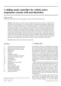
design. v- gap metric was utilized to validate the estimated uncertainty bounds for improved robust stability. The variable structure system was presented by ,Utkin, 1977. and indicated that variable structure control is unaffected to parameters perturbations and external disturbances. Recently, some applications have been developed using sliding mode control and adaptive control. For MIMO case the sliding mode control is designed based on hierarchy procedure as given in ,Utkin, 1992. As an alternative procedure design a unit control method is proposed for the MIMO system which preserved the sliding mode robustness with respect to the uncertainty in system parameters and to the external disturbances. The control law is designed using Lyapunov function where the root of this approach may be found in papers by ,Gutman and Leitmann, 1976. and ,Gutman, 1979. In the present work the sliding mode control algorithm is employed to design a robust control system to AMB based on the unit control approach in the presence of model uncertainty and disturbances. The paper is organized as follows. In Section 2, the dynamics of AMB system with a flexible rotor is described. In Section 3, a unity sliding mode controller with pole placement control is developed. Simulation results are presented in Section 4. Conclusions are provided in Section 5. 2. DYNAMIC MODELING OF THE AMB SYSTEM In AMB systems, more than one actuator can be used in order to control the rotor levitation along several degrees-of-freedom (DOF). In this case, actuators are usually assembled as pairs facing each-other. This allows attracting the rotor in two opposite directions along one axis. Typically, the basic components of an AMB are: electromagnets, iron core, winding, rotor, position sensor, controller and power amplifier, as shown in Fig.1. The control objective is to manipulate the coil current i(t) so that the vertical position of the rotor x(t) tracks the desired trajectory. AMB are usually available in many configurations like radial bearings, in which the main purpose is to guarantee the levitation even in case of total failure of an actuator axis. 2.1 Theoretical Model The force generated by an electromagnetic actuator Fig.1 can be derived using magnetic circuit analysis and conservation of energy technique as in ,Schweitzer, 1994. (1) The resulting nonlinear magnetic force Equation (1) is proportional to the square of the coil current and inversely proportional to the square of the air gap between the actuator and the rotor . is the permeability of free space ( ), is the number of turns in the coil, and is the area of the air gap ,Schweitzer, 1994. In order to develop a model based control of the system in Fig.2, the electromagnetic force Equation (1) is linearized about a nominal operating point and an accurate dynamical model is formulated in ,Choi et. al., 2006. The linearized system dynamics for the AMB system were obtained using a Lagrangian analysis of Fig.2, then they were represented using a state vector x composed of the rotor displacements and their time derivatives. ̇
(2) 92
Number 6
Volume 21 June 2015
Journal of Engineering
(3) Where ,Choi et. al., 2006. [ ̇ ],
[
,
]
[
[
,
],
[
],
[ ] ,
[
]
]
[
[
] ,
,
]
[
[
and
],
]
with system parameters and ). The resulting continuous-time model is
(nominal speed: unstable, with eigenvalues
(5) 3. SLIDING MODE CONTROLLER DESIGN This section proposes a unity sliding mode control strategy for the AMB system. A detailed study of the sliding mode control algorithm is presented in the presence of matched uncertainties and external disturbance with the AMB model. 3.1 Representation of uncertainties Starting by rewriting Equations (2) to include the parametric uncertainties and disturbance effect ( ) ̇
(6)
where , , and . Here matched uncertainty in the matrices respectively. In addition disturbance satisfies the matching condition. Namely ( ) Since (
refer to the ( ) is an external
( )
(7)
) is a controllable pair, then the following control signal is proposed:
93
Number 6
Volume 21 June 2015
Journal of Engineering
(8) where
is chosen such that the matrix (9)
is Hurwitz with the desired characteristic roots. Consequently Equation (6) becomes: ( ) ̇ Now let the uncertainty in matrix
(10) can be written as (11)
Then the bracket *
( )+ can be written as:
( )
*
( )+
*(
Assumption: The matched uncertainty Accordingly ‖(
)
( )‖
where ‖
‖
, ‖
‖
‖ ‖ ,‖ ( )‖
)
( )+
and external disturbance ‖
(12) ( ) are bounded.
‖
(13)
, and α, , are positive constants.
Detailed formulation of the derivation of uncertainties is provided in Appendix A. 3.2 Unit control design The objective of this section is to demonstrate a design method for discontinuous control enforcing sliding mode in some manifold without individual selection of each component of control as a discontinuous state function. The approach implies design of control based on a Lyapunov function selected for a nominal system. The control is to be found such that the time derivative of the Lyapunov function is negative along the trajectories of the system with perturbations caused by uncertainties in the plant model and environment conditions ,Utkin et. al., 2009. From previous discussion, the unit control signal is proposed as (‖ ‖)
‖
(14)
‖
where ‖⋅‖ is the Euclidean norm, and hence the control law in Equation (8) becomes: (‖ ‖)
‖
(15)
‖
Since the system ̇ is asymptotically stable, then by the converse theorem as given in ,Khalil, 2002. there is a Lyapunov function with a positive definite matrix (16)
94
Number 6
such that ̇ ̇
Volume 21 June 2015
. To this end, differentiate
*
Journal of Engineering
with respect to time, to get:
( )+
*
( )+ (17)
The unite vector gain (‖ ‖) is evaluated such that ̇ is negative definite. As a result, ̇ is rewritten as follows: ̇
*
( )+
(18)
Now let us consider the following: (
)(
)
‖
‖
‖
‖
‖
‖
‖
‖,
and *(
)
( )+
‖
‖‖(
‖
)
‖( ‖ ‖
( )‖ )
then Equation (18) becomes: ̇
‖ ‖
‖
‖ ‖
‖
‖( ‖ ‖
‖( ‖ ‖
) )
‖
‖*
‖
‖* (
‖ ‖ )
+ ‖ ‖
+
Now for (‖ ‖)
(
)
* ‖ ‖
+
(19)
then ̇ becomes; ̇
‖
‖
‖ ‖
(20)
This implies that the trajectory reaches the sliding surface in a finite time and remains on the sliding surface for all future time. Note that the finite reaching time is a consequence of the unit vector term
‖
‖
in the
control law (Equation (15)), and the reaching time is directly related to the magnitude of the gain (‖ ‖) ,Khalil, 2002. Eventually for the system dynamics in Equation (6) the control law is given by
95
Number 6
(‖ ‖) where
Volume 21 June 2015
Journal of Engineering
(21)
‖ ‖
is the switching function vector given by
,
-
, and (‖ ‖)is as in Equation (19). In addition the norm of the vector appears in the unit vector is given by (the induced inner product norm); ‖ ‖
√
which
(23)
Due to the presence of a discontinuous term in the control law (‖
‖
in Equation (21)), the chattering
behavior will be induce in system response. Many methods have been developed to eliminate the chattering problem, as in the case of replacing the discontinuous term by an approximate continuous form as for example the saturation function (see ,Utkin, et. Al., 2009. The price paid to eliminate the chattering effect by approximating the discontinuous term is that the state will be only regulated to a region near the origin. The size of this region depends on the approximation form. As an alternative solution to the chattering problem with preserving the finite time reaching property is by reducing the amplitude of the switching term in the control law. In the present work the amplitude of the switching term (‖ ‖) is taken as a function to the state rather than a constant value. This will help in reducing the chattering around the origin where (‖ ‖) will be equal to ( ) . ( ) In the following section the unity sliding mode control law as given in Equation (21) is applied to design a robust nonlinear control for the AMB system with considering both the uncertainty in system model and the effect of the external disturbances. 4. SIMULATION RESULTS According to the plant description in Section 2.1 and using Equations (2) and (3), simulation of the AMB is developed. MATLAB is used to simulate the AMB controlled system. The first experiment was accomplished using the following linear state feedback control equation: , where K is matrix selected to satisfy that Equation (9) is Hurwitz with the desired characteristic roots. Accordingly let the following set of closed loop poles are selected as: ,
-
Figure 3 shows the resulted states response of the controlled AMB system. The disturbance effects due to noise variations are not considered in this case. Subsequently, the controller can effectively regulate the system as shown in Fig.4. Then, the uncertainty and disturbance effects are included in the simulation by considering Equation (6), using the same previously designed state feedback controller. The applied disturbance is given by:
96
Number 6
Volume 21 June 2015
,
Journal of Engineering
-
where is uniformly distributed pseudorandom number. The transients of the system are drastically affected, as shown in Fig. 5.We allowed ±10% parameter variations for the matrices and and further assumed 10% to 35% magnitude changes in the ( ) term. Consequently, the matrices are calculated by equations (A-5) and (A-8) respectively (Appendix A). The parameter variations constitute and is assumed to have only matched uncertainty. The external disturbance is a random variable with zero mean and unit variance which is assumed to have only matched disturbance in the simulation. Accordingly, the parameters, and will be equal to 1.7129, 0.2105 and 0.6393 respectively. The parameter is set to 0.01 as a positive value in order that ̇ becomes negative definite (Equation (20)). In the same time is selected small to reduce chattering that induced due to a high gain value of the discontinuous term (‖ ‖). The control signals are shown in Fig.6. The evaluated coefficients of vector (Equation (23)), can be seen in Fig.7 while Fig.8 presents the resulted norm of . It is clear that the linear state feedback controller cannot overcome the effects of uncertainties and presence of disturbance. Therefore, further improvement is required to be applied, as described in Section (3); the term unity control is included as described in Equation (21). The switching gain (‖ ‖), which is responsible for reject the uncertainty in system parameters and the external disturbance effects, varies continuously from 0.9876 and to less than 0.014 rapidly in less than 9 minutes, which reflects the effectiveness of the added term to the control signal. Figure 9 presents the transient response of the system while Fig.10 presents the control signals. Fig.11 presents the norm of the S function. Fig.11 also reveals the objective of the proposed controller in regulating the switching function vector to the origin in finite time. Here the time required to reach the origin is about 15 seconds. Further decrease in the reaching time can be gotten by increasing the gain of the unit control according to Eq.(21). Then to further explore the robustness of the developed controller, another larger value of disturbance is applied as: ,
-
The transient response of the system is shown in Fig.12 and Fig.13 show the control signals. The norm of the S function is given in Fig.14. It is clear that the new controller can effectively overcome the disturbance effects. Robust performance is also guaranteed in this case as proved in Section (3.2). 5. CONCLUSIONS
This paper presents a derivation for a unity sliding mode controller design for a linear uncertain MIMO system subjected also to external disturbances. The proposed control is robust with respect to the uncertainty in system model and to the matched external disturbances since it was derived based on making the derivative of a candidate positive definite Lyapunov function negative definite. The developed unity sliding mode control was effectively derives the uncertain AMB system model to robust stability and performance conditions under the existence of matching condition. The simulation results, which are carried out for ±10% parameter variations for the matrices A and B and 10% to 35% magnitude changes in the disturbance term ( ), clearly demonstrated the robustness and the effectiveness of the proposed unity sliding mode controller. In addition the
97
Number 6
Volume 21 June 2015
Journal of Engineering
results show that the effect of the chattering problem in sliding mode control is reduced via the use of a variable switching gain (‖ ‖) which has its minimum value at the origin. REFERENCES Abdul Somad F.,2007, "System Identification and Control of Magnetic Bearing Systems, School of Electrical Engineering", Master Thesis, Victoria University. Arredondo and Jugo J.2007, "Active Magnetic Bearings Robust Control Design based on Symmetry Properties". Proceedings of the 2007 American Control Conference, USA, July 11-13. Buckner G. D., 2002, "Intelligent bounds on modeling uncertainty: applications to sliding mode contro", IEEE Trans. On system, man, and Cybernetics-part c, applications and reviews, 32(2), 113-124. Cao G., Fan S. and Xu G.2004, "The Characteristics Analysis of Magnetic Bearing Based on H-infinity Controller". Proceedings of the 51th World Congress on Intelligent Control and Automation. Hangzhou, P.R. China, June 15-19. Choi H.,.Buckner G.D, and Gibson N.S., 2006, "Neural robust control of high-speed flexible rotor supported on active magnetic bearings". in Proc. Of the 25th American Control Conference, Minneapolis, Minnesota, USA, June 14-16, the AACC and IEEE. Gibson, N.S., Choi H. & Buckner G.D., 2003, "H∞control of activemagnetic bearings using artificial neural network identification of uncertainty". System, Man, Cybernetics, 2003.IEEE International Conference, 2, 1449-1456. Gibson, N.S., Buckner,G.D, Choi H. and Wu, F., 2005, "Confidence interval networks for bounding model uncertainty: experimental evaluations on an active magnetic bearing system". IEEE Mid-summer workshop on soft computing in industrial applications, Helsinki University of Technology, Espoo, Finland, June 28-30. Gosiewski Z. and Mystokowski A., 2007, "Robust control of active magnetic bearing suspension: Analytical and experimental study". Mechanical systems and Signal Processing. Gutman S, and Leitmann G., 1976," Stabilizing Feedback Control for Dynamic Systems with Bounded Uncertainties". IEEE Conf. Decision Control .94–99. Gutman S., 1979, "Uncertain Dynamic Systems: A Lyapunov Min-Max Approach". IEEE Trans Automatic Control AC-24:437–449.
98
Number 6
Volume 21 June 2015
Journal of Engineering
Habib, M. M. and Hussain J. I., 2003, "Control of Dual Acting Magnetic Bearing Actuator System Using Fuzzy Logic". IEEE International Symposium on Computational Intelligence in Robortics and Automation, Kobe, Japan, IEEE. Hung, J. Y. 1995, "Magnetic Bearing Control Using Fuzzy Logic". IEEE Transactions on Industry Applications. 31(6), 1492-1497. Khalil H. K., 2002, "Nonlinear Systems".3rd Edition, Prentise Hall, USA. Motee, N. and Queiroz M. S. D., 2002, "Control of Active Magnetic Bearing.Proc.Ofthe 41st IEEE Conference on Decision and Control", Las Vegas, Nevada, USA, IEEE. Nair S.S., Vaidyan M. V. and Joy M. L.2009,"Generalized Design and Disturbance Analysis of Robust H infinity Control of Active Magnetic Bearings ". IEEE/ASME International Conference on Advanced Intelligent Mechatronics Suntec Convention and Exhibition Center Singapore, 1124-1129. July 14-17. Polajzer, B., and Dolinar, D., 1999, "Modeling and Control of Horizontal-Shaft Magnetic Bearing System". IEEE, 1051-1055. Raafat S.M., Akmeliawati R., and Logow A., 2011, "Intelligent Estimation of Uncertainty Bounds of An Active Magnetic Bearings Using ANFIS". ICIEM 2011, China. Schweitzer G., Bleuler H. and Traxler A. 1994, "Active Magnetic Bearings"..Hochschul verlag AG der ETH Zürich. Sivrioglu S. and Nonami K., 1996, "LMI Approach to Gain Scheduled H∞Control beyond PID Control for Gyroscopic Rotor-Magnetic Bearing System". Proceedings of the 35th FA19 Conference on Decision and Control, Kobe, Japan, 3694-3699. Utkin V. I., 1977, "Variable structure systems with sliding modes". IEEE Trans Automat Contr..22:212–222. Utkin V. 1., 1992, "Sliding Modes in Optimization and Control". Springer-Verlag, New York. Utkin V. I., Guldner J., and Shi J., 2009, "Sliding Mode Control in Electro-mechanical Systems", CRC Press. Taylor & Francis Group. Yoon S. Y., Lin Z., and Allaire P. E., 2013, "Control of Surge in Centrifugal Compressors by Active Magnetic Bearings". Springer-Verlag London. Zhang, H., and Lin Z., 2002, "A Convex Optimization Approach to Robust Controller Design for Active Magnetic Bearing Suspension Systems".8th International Symposium on Magnetic Bearing, Mito, Japan.
99
Number 6
Volume 21 June 2015
Journal of Engineering
Appendix A: Computing the Uncertainty Matrices 1) Let
be written as: [
]
(A.1)
where
. Also let
[
be written as follows:
]
(A.2)
,
-
Now
(A.3)
becomes:
[
]
],
[
where the matrix
-
[
] (
is an invertable matrix (
)
). Therefore
}
(A.5)
)
, Let [
be written as:
]
(A.6)
and with the aid of Equation (A.2), we can write [
]
[
(A.4)
]
[
as:
]
(A.7)
Solving for (A.8) Then, by taking ‖
‖
‖
‖
(A.9)
and ‖
‖
(A.10)
where ‖ ‖ refer to the 2-norm. Therefore (‖ ‖) will be evaluated from 100
Number 6
(‖ ‖)
(
)
* ‖ ‖
Volume 21 June 2015
Journal of Engineering
+
(A.11)
Figure1. AMB operating principals ,Gibson et. al., 2003.
Figure 2. Generalized rigid rotor supported by two radial bearings ,Choi et. al., 2006.
101
Number 6
3
x 10
Volume 21 June 2015
Journal of Engineering
-3
2 x(1) x(2) x(3) x(4) x(5) x(6) x(7) x(8)
(x1-x8)
1 0 -1 -2 -3 0
5
10 Time (sec.)
15
20
Figure 3. The transient responses of the AMB system under pole placement control, x(0)=2*103states x(1)-x(8).
0
u(1)-u(4)
-2
-4 u(1) u(2) u(3) u(4)
-6
-8 0
5
10 Time (sec.)
15
Figure 4. The control signals u(1)-u(4).
102
20
Number 6
1.5
x 10
Volume 21 June 2015
Journal of Engineering
103
The states (x1-x8)
1 0.5
x(1) x(2) x(3) x(4) x(5) x(6) x(7) x(8)
0 -0.5 -1 -1.5 0
5
10 Time (sec.)
15
20
Figure 5. The transient responses of the disturbed AMB system under pole placement control, x(0)=2*10-3.Disturbance of Equation (28) is applied.
Control signal (u(1)-u(4))
5
x 10
102
u(1) u(2) u(3) u(4) 0
-5 0
5
10 Time (sec.)
15
Figure 6. The control signals u(1)-u(4).
103
20
Number 6
1
x 10
Journal of Engineering
102
s(1) s(2) s(3) s(4)
0.5
s(1)-s(4)
Volume 21 June 2015
0
-0.5
-1 0
5
10 Time (sec.)
15
20
Figure 7. The evaluated function S.
5
x 10
100
4
|S|
3 2 1 0 0
5
10 Time (sec.)
Figure 8. The resulted norm (S).
104
15
20
Number 6
x 10
Volume 21 June 2015
Journal of Engineering
-3
x(1) x(2) x(3) x(4) x(5) x(6) x(7) x(8)
The states (x(1)-x(8))
2 1 0 -1 -2 0
5
10 Time (sec.)
15
20
Figure 9. The transient responses of the disturbed AMB system under pole placement and unity control, x(0)=2*10-3. Disturbance of Equation (28) is applied.
Control signals (u(1)-u(2))
2 0 -2 -4
u(1) u(2) u(3)
-6
u(4) -8 0
5
10 Time (sec.)
15
Figure 10. The control signals u(1)-u(4).
105
20
Number 6
Volume 21 June 2015
Journal of Engineering
0.06 0.05
|s|
0.04 0.03 0.02 0.01 0 0
5
10 Time (sec.)
15
20
Figure 11. The norm |S|
The states (x(1)-x(8))
4
x 10
-3
x(1) x(2) x(3) x(4) x(5) x(6) x(7) x(8)
2
0
-2
-4 0
5
10 Time (sec.)
15
20
Figure 12. The transient responses of the disturbed AMB system under pole placement and unity control, x(0)=2*10-3. Disturbance of Equation (29) is applied.
106
Number 6
Volume 21 June 2015
Journal of Engineering
1
Control signals (u(1)-u(4))
0 -1 -2 -3 -4 u(1) u(2) u(3) u(4)
-5 -6 -7 0
5
10 Time (sec.)
15
20
Figure 13. The control signals u(1)-u(4).
0.06 0.05
|S|
0.04 0.03 0.02 0.01 0 0
5
10 Time (sec.) Figure 14. The norm |S| 107
15
20