Jan 13, 2005 - A gas-kinetic scheme, based on the Xu-Prendergast BGK scheme, ... new viscous discretization technique based on gas-kinetic concepts in ...
43rd Aerospace Sciences Meeting and Exhibit, Jan 10-13, 2005, Reno, NV
Unstructured Algorithms for Inviscid and Viscous Flows Embedded in a Unified Solver Architecture: Flo3xx Georg May∗, Antony Jameson† Stanford University, Stanford, CA, 94305, USA This paper reports recent progress towards a new platform for computational aerodynamics on arbitrary meshes, tentatively designated Flo3xx. This tool is designed for maximum flixibility to serve as both an industrial strength flow solver on general grids, and as a framework for advanced research in the area of CFD and aerodynamic design. Such a flexible platform is crucial for transfering new research to industrial applications. We describe the capabilities and methods used in this tool, and show results from initial validation on inviscid and viscous testcases. Furthermore some open issues in CFD on unstructured grids will be addressed, such as viscous discretization and multigrid methods in an unstructured context.
I.
Introduction
Numerical algorithms that use unstructured grids have become increasingly popular within the CFD community. For viscous flow calculations hybrid grids are predominantly used, with prisms or hexahedra to resolve shear layers, and tetrahedra for the rest of the computational domain. However, structured meshes are still being used as well, while some researchers prefer Cartesian meshes. The variety of different meshes being used today and the immense effort required for the generation of high-quality meshes were a primary motivation for the development of our new hybrid solver architecture Flo3xx for three-dimensional viscous flow, which operates on arbitrary meshes, and different discretization techniques, such as cell-centered, or cell-vertex discretization. Furthermore, Flo3xx is capable of reproducing the exact residuals of structured flow solvers when operating on structured meshes. We will give a general overview of this new tool in the first section. It is desirable to formulate all algorithms in a way that does not depend on the mesh topology. However, viscous discretization traditionally depends heavily on the type of mesh being used. Furthermore, the choice of control volumes is quite important in this context. Gradients may be needed at the element centroids or the nodes for the purpose of state reconstruction and/or turbulence source terms. They may also be needed at cell interfaces, when computing the the rate-of-strain tensor for viscous fluxes. These interfaces may be given by the faces of the primary elements or by polygonal constructs arising e.g. from the median dual. A construction of the gradient at cell cetroids or nodes and a subsequent suitable averaging for the computation of the rate-of-strain tensor has been used by many researchers, but it is not at all obvious how this can be done accurately and robustly in a completely mesh transparent way. We will present a new type of gas-kinetic viscous discretization, which is inspired by recent success of gas-kinetic schems, such as the Xu-Prendergast1 ∗ PhD
Candidate, Department of Aeronautics and Astronautics, Stanford University, AIAA Member. Department of Aeronautics and Astronautics, Stanford University, AIAA Member. c 2005 by the authors. Published by the American Institute of Aeronautics and Astronautics, Inc. with Copyright ° permission. † Professor,
1 of 15 American Institute of Aeronautics and Astronautics Paper 2005-0318
scheme, based on the BGK equation. Viscous fluxes are computed from a reconstructed distribution function in each cell, which potentially reduces the mesh dependence of the viscous discretization. Initial results have been obtained using this method with the new architecture, which will be presented in section III. A strategy for the automatic generation of unstructured coarse meshes based on the edge-collapsing technique has been developed and successfully used for inviscid computations with purely tetrahedral meshes. For viscous flow, an extension for hybrid grids, involving prismatic boundary layers has been developed. This will be presented in section IV.
II.
A New Flow Solver Architecture: Flo3xx
Flo3xx is a flow solver for the Euler and Navier-Stokes equations intended for use with any type of mesh and choice of control volumes. This new solver will be introduced in this section along with inviscid validation results. The subjects of viscous discretization and unstructured multigrid methods will be deferred to later sections. A.
Support for Arbitrary Meshes and Different Discretization Techniques
j
i
Figure 1. Examples of different mesh types and discretization techniques. From left to right: Structured, unstructured in cell-centered discretization (variables are stored at the cell-centers), unstructured in cellvertex discretization using the median dual (variables are stored at the nodes), Cartesian.
Different types of meshes (structured, unstructured, Cartesian) as well as conceptually different methods of discretization are used in computational fluid dynamics today. Examples of discretization techniques are cell-centered discretization or cellvertex discretization with one of the possible ways to define dual meshes from a given N1 N N2 primary mesh topology. Figure 1 illustrates different mesh types and different discretization techniques. The newly developed program Flo3xx can operate on any of the above mesh types and discretization techniques. In fact, the flow solver module is at present completely oblivious to the underlying mesh topology so that it can run, in principle, on arbitrary meshes. A face-based data structure is used, which Figure 2. Two dimensional illustration recognizes pointers from cell interfaces to adjacent nodes as the only connectivity of the face-based data information. This is illustrated in figure 2. Regardless of the mesh topology, there structure. will always be a finite number of interfaces separating exactly two control volumes, including halo cells at boundaries. By looping over these interfaces all necessary flux computations can be carried out. The pseudo-code in figure A illustrates the basic algorithm used in the flow solver module. While this algorithm is simple, the connectivity information used is not normally the one stored in primary meshes. Computational complexity is shifted to the preprocessing stage, where the necessary data structure is generated along with metric data. Currently, preprocessing is implemented to provide metrics for the median dual mesh and the primary mesh for the four most common element types tetrahedra, prisms, pyramids, and hexahedra.
2 of 15 American Institute of Aeronautics and Astronautics Paper 2005-0318
Preprocessing for hexahedra allows the treatment of structured meshes in an unstructured context. For structured meshes the data structure can also be augmented to recover the treatment that is normally used for this type of mesh. Figdo n=nface1,nface2 ure 4 illustrates the usual stencil used for a second order flux N1 = ncf(1,n) computation on a structured mesh. The blue cell centers in N2 = ncf(2,n) figure 4 are pointees of the face between them in an unstrucflux(N) = f(solution(N1) , solution(N2)) tured context. By creating an additional level of pointers to residual(N2) = residual(N2) + flux(N) residual(N1) = residual(N1) - flux(N) the next-but-one neighbors (green cell centers), it is possible end do to reproduce the structured algorithms with the unstructured code. Note that there are thus two ways in which structured do i=ncell1,ncell2 meshes can be treated in Flo3xx: One way is to look at them as solution(i) = solution(i) - residual(i) end do unstructured hexahedral meshes and use a general-mesh treatment, involving gradient reconstruction (to be described beFigure 3. Basic solution algorithm in Flo3xx low). Another way is to use the described extra data structure to reproduce the exact structured algorithms, which is faster compared to first method. It also serves to asses the minimum overhead that is incurred compared to a structured code due to the indirect addressing. Numerical experiments have shown this overhead to be around 25%. Cell-centered discretization using the primary mesh or cell-vertex discretization using the median dual mesh can be selected at run-time, the only difference being the preparation of the metric data. Usually, subtle differences between cell-centered and cell-vertex discretization exist even in a mesh transparent flow solver module, for example at the boundaries. In this implementation a unified treatment of the boundaries has Figure 4. Stencil for 2nd order been chosen, using halo-cells at boundaries for any kind of mesh, i.e. for flux computation on a structured mesh. cell-vertex schemes boundary conditions are not enforced at the nodes. During preprocessing boundary nodes become dual cell centers, which are no longer located on the boundary, but shifted to the dual cell centroids. The construction of halo cells proceeds in the same manner as for cell-centered discretization. do i=ncell1,ncell2 set residual(i) to zero end do
B.
Numerical Methods
Several spatial discretization techniques are implemented in Flo3xx. Convective and diffusive terms are discretized using the H-CUSP or the E-CUSP scheme.2 The JST scheme3 is also available. These schemes are well known and well proven. A gas-kinetic scheme, based on the Xu-Prendergast BGK scheme, is also implemented, wich actually computes the full Navier-Stokes fluxes from locally reconstructed gas distribution functions. This is subject of another paper4 and will not be discussed here. We will, however introduce a new viscous discretization technique based on gas-kinetic concepts in section III, along with conventional viscous discretization techniques. A gradient-based linear reconstruction is used to construct left and right states for flux computations. Let index i denote a cell of the mesh, and index f a face of the cell. The reconstruction is written wf = wi + φ∇wi (xf − xi ) .
(1)
Here, w is a conserved flow variable. A limiter φ has to be used to prevent oscillations in nonsmooth regions. Currently Venkatakrishnan’s limiter is used ½ ¾ α2 + 2α∆w + ² φ = min , (2) f ∈L α2 + α∆w + 2∆w2 + ²
3 of 15 American Institute of Aeronautics and Astronautics Paper 2005-0318
where L denotes the set of faces separating cell i from its neighbors. ∆w = ∇wi (xf − xi ) and ( β (wmax − wi ) ∆w ≥ 0 α= , β (wmin − wi ) ∆w < 0
(3)
where wmax and wmin are local extrema of w over all cells adjacent to faces in L. Strict positivity is not enforced at smooth extrema, where ∆w is small. However, the value of the limiter approaches zero for large ∆w, which ensures positivity at discontinuities. The constant β in equation 2 can be used to tune the limiter. Normally, β = 1. The constant ² ensures that the limiter becomes inactive whenever both α and ∆w are small, i.e. in smooth regions. C.
Time Stepping
Explicit Runge-Kutta time stepping with convergence acceleration techniques such as local time stepping, enthalpy damping, residual smoothing, and multigrid provides a good compromise between computational cost and complexity on one hand, and convergence rate on the other hand. This has been the default implementation in Flo3xx. Recently the nonlinear symmetric Gauss-Seidel method, proposed and validated on structured meshes by Jameson and Caughey,5 has proven to be an attractive alternative, offering superb convergence characteristics at a computational cost comparable to the Runge-Kutta method. For Flo3xx a formulation for unstructured grids has been implemented. To outline the method consider a flux-split semi-discretization of the one dimensional conservation law dw + Dx− f + (w) + Dx+ f − (w) = 0 , dt ±
where the splitting is such that the jacobians A± = ∂f ∂w have positive and negative eigenvalues, respectively. Dx± are forward and backward difference operators. The linearized implicit scheme becomes © ¡ ¢ª I + λ δx+ A− + δx− A+ δw + ∆tR = 0 , (4) where λ =
∆t ∆x
and R is the residual. Upon rearranging, ¡ ¢ − + + δwi + λ A− i+1 δwi+1 − Ai δwi + Ai δwi − Ai−1 δwi−1 + ∆tRi = 0 ,
(5)
we obtain the symmetric Gauss-Seidel scheme as ¡ ¢ (1) (1) (1) − + δwi + λ A+ i − Ai δwi − λAi−1 δwi−1 + ∆tRi = 0 , (2)
δwi
¡ ¢ (2) (2) (1) (1) − − + + λ A+ =0. i − Ai δwi + λAi+1 δwi+1 − λAi−1 δwi−1 + ∆tRi
By noting that the terms ∆tRi − (1)
(1) ∆t + ∆x Ai−1 δwi−1
(1)
are a linearization of ∆tRi evaluated with wi−1 = wi−1 +
δwi−1 , the scheme can be recast as ¾ ½ ¢ ∆t ¡ + (1) (01) − I+ A − Ai δwi + ∆tRi ∆x i ½ ¾ ¢ ∆t ¡ + (2) (12) − I+ δwi + ∆tRi A − Ai ∆x i
= 0,
(6)
= 0,
(7)
where (01)
Ri
(12)
Ri
´ 1 ³ − (0) (0) (0) + (1) , fi+1 − fi− + fi+ − fi−1 ∆x ´ ³ 1 (2) (1) (1) + (1) , = f− − fi− + fi+ − fi−1 ∆x i+1
=
4 of 15 American Institute of Aeronautics and Astronautics Paper 2005-0318
and (1)
wi
(0)
+ δwi
(2)
= wi
= wi
win+1 = wi
(1)
(0)
, (2)
+ δwi
,
fi±
(1)
= f ± (wi ) ,
fi±
(2)
= f ± (wi ) .
(1)
(2)
In the limit ∆t → ∞ the sweeps 6 and 7 reduce to |A|δw(1) + σR(01) |A|δw(2) + σR(12)
=0 =0,
(8) (9)
where |A| is the absolute Jacobian matrix, |A| = A+ − A− , and σ is a relaxation factor ∼ 1. The extension to higher dimensions and a finite-volume formulation can be accomplished by replacing |A| with the sum of absolute directed Jacobians. The generic formulation 8,9 remains valid. In practice the nonlinear formulation reduces computational complexity, since a simple cell-based algorithm can be used, in which the fluxes at all faces surrounding the cell are computed, and the solution in the cell is updated before moving to the next cell. This means that fluxes are computed twice at each face during both the forward and backward sweep. Thus the baseline scheme is roughly equivalent in complexity to a four stage Runge-Kutta scheme. For an unstructured implementation two major differences compared to the structured version need to be addressed. Firstly, there is no obvious ordering in which the updates are to be performed. At the very least, a reasonably balanced stencil should be generated by the ordering, so that flux computations always use a combination of updated and non-updated cells. For external aerodynamics it has been found that performing the sweeps in incresing and decreasing xn , where xn is the free stream direction, yields good results. Thus the nodes are ordered in increasing xn . Should a boundary of the domain be aligned with a direction normal to xn an arbitrary ordering in that direction could result. This can be prevented by rotating the ordering direction very slightly about an axis normal to xn . The second important difference is that, unlike structured meshes, where the reconstruction can be performed on the fly using a simple stencil of direct neighbors and next-but-one neighbors, for unstructured meshes the reconstruction is precomputed using gradients and limiters. Since the solution variables are continuously updated during the loop over the cells, corrections to the reconstruction must be made. In the current implementation the reconstruction for the SGS scheme uses a least-squares method to compute gradients. For a cell, i say, the gradient is obtained by nminimizing the functional 1X 2 {∇wi · ∆xl − ∆wl } (10) 2 l∈L
where l is the index of a face separating cell i from a neighboring cell j. All such faces form the set L. We denote by ∆xl = xi − xj the distance between the cells i and j, and ∆wl is defined in a similar fashion. This leads to X ~ i= A∇w ∆wl ∆~xl (11) l∈L
where
X ∆xl ∆xl A= ∆xl ∆yl l∈L ∆xl ∆zl
∆xl ∆yl ∆yl ∆yl ∆yl ∆zl
∆xl ∆zl ∆yl ∆zl . ∆zl ∆zl
(12)
Suppose the value of w in node i has changed according to w e = w + dw, and we wish to update the gradient in node i and the surrounding stencil. The matrix A in equation 12 depends only on metric terms, and its 5 of 15 American Institute of Aeronautics and Astronautics Paper 2005-0318
inversion can be precomputed and stored for each node. Let the new value of the gradient in i be denoted by w. e By inspection of equation 11 we see that ~w ~ + A−1~r , ∇ e = ∇w (13) where ~r = dwi
X
(~xi − ~xj )
j
for cell i and ~r = dwi (~xi − ~xj )
(14)
for any node neighboring cell j. The limiter can be updated in a similar fashion. D.
Inviscid Validation 1.5 AIRPLANE − Tetrahedral Mesh Flo3xx − Tetrahedral Mesh Flo3xx − Structured Mesh 1
−cp
0.5
0
−0.5
y/b = 0.2 −1 0
0.1
0.2
0.3
0.4
0.5
0.6
0.7
0.8
0.9
1
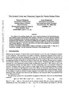
X/C Figure 5. Pressure distribution in the wing section y/b = 0.2 for the Onera M6 wing at Mach number M = 0.84 and α = 3.06o angle of attack. Results are shown for a structured mesh with 1,1 million nodes and for a tetrahedral mesh with 316,000 nodes.
Figure 5 provides initial validation of the unifiedmesh algorithm. Both a structured mesh with approximately 1.1 million nodes and an unstructured tetrahedral mesh with 316,000 nodes have been used to calculate the flow for the Onera M6 testcase at Mach number M = 0.84 and α = 3.06o angle of attack. The cp distribution at the wing section y/b = 0.2 is compared to results obtained with the solver AIRPLANE on the same unstructured tetrahedral mesh. All computations have been carried out using cell-vertex discretization on a three-level multigrid sequence. Convergence histories for the lift coefficient for both Runge-Kutta time stepping and the nonlinear SGS scheme are shown for several meshes in figure 6. It can be observed that both methods converge well. The SGS scheme, however, reaches the steady state faster than the Runge-Kutta scheme. For both schemes the convergence is nearly mesh independent. For the two coarser meshes in 6 a three mesh multigrid sequence has been used, whereas for the finest mesh a four mesh sequence was employed. All multigrid computations were carried out using a
w-cycle.
III.
Viscous Discretization
Since gradients are needed for state reconstruction they are initially computed for the nodes of the primary mesh or the centroids of the primary elements, depending on the discretization type chosen. For viscous dicretization the gradients must be evaluated at the interfaces between edjacent cells. This can be done by a suitable average, which typically depends on the mesh structure and choice of control volume. Since the goal for the computational platform Flo3xx is complete mesh transparency, this dependence on the mesh topology is unsatisfactory. In the current implementation gradients are constructed using either the unweighted least-squares method described in section II or a gauss-type reconstruction, i.e. Z 1 ∇wi = φ¯ dA , (15) Vi A 6 of 15 American Institute of Aeronautics and Astronautics Paper 2005-0318
Onera M6, α = 3.06, Ma = 0.84 (640K Nodes)
Onera M6, α = 3.06, Ma = 0.84 (316K Nodes)
0.45 Nonlinear SGS Rung−Kutta
0.4
0.35
Nonlinear SGS Runge−Kutta
0.35
0.3
0.3
0.25
0.25
0.35
0.15
0.2
0.1
Nonlinear SGS Runge−Kutta
0.05 20
40
60
80
100
0.2 0.15
0.1
0.15 0.1 0
0.2
CL
CL
CL
0.3 0.25
0.05
0
20
40
Cycles
60
80
100
0
20
Cycles
(a) Onera M6 Testcase on 94k node tetrahedral mesh
(b) Onera M6 testcase on 316k node tetrahedral mesh
40
60
80
100
Cycles
(c) Onera M6 testcase on 640k node tetrahedral mesh
Figure 6. Comparison of convergence history of the lift coefficient for the nonlinear SGS scheme and RungeKutta time-stepping.
where Vi is the cell volume, and the overbar denotes a suitable face average. For conventional viscous discretization an initial value for the gradient at the cell interface may be obtained by averaging the values of adjacent cells, φi and φj , to give i 1h (∇φ)i + (∇φ)j . (16) (∇φ)ij = 2 Subsequently a correction in the direction ~sij is applied to avoid odd-even decoupling, where ~sij =
~rj − ~ri . |~rj − ~ri |
This leads to the following gradient on the interface · ¸ φj − φi (∇φ)ij = (∇φ)ij − (∇φ)ij · ~sij − · ~sij . |~rj − ~ri |
(17)
This modification results in a stable discretization of the viscous terms and does not affect the accuracy as long as the interface integration point is located halfway between the two cell-centers. This, however, is only the case for the median dual control volume, rendering this type of viscous discretization highly mesh dependent Using concepts of kinetic gas theory, viscous discretization can be accomplished in a different fashion. Many researchers have used the Boltzmann equation or its BGK simplification,6 i.e. the BGK equation, as a basis for the construction of numerical fluxes.7, 1 Firstly we note that the Navier-Stokes equations can be obtained by Chapman-Enskog expansion of both the full Boltzmann equation as well as the BGK equation, the difference being only in the values of the transport coefficients. Suppose that f is a distribution function describing the fluid state Φ = (ρ, ρu, ρv, ρw, ρe)T , i.e. Z Φ(x, y, z, t) = φ f (x, y, z, u, v, w, t, ξ) du dv dw dξ , (18) where
µ φ(x, y, z, t) =
1 1, u, v, w, (u2 + v 2 + w2 + ξ 2 ) 2
¶T ,
and u, v, w are the phase-space velocities. The variable ξ stands for internal degrees of freedom. 7 of 15 American Institute of Aeronautics and Astronautics Paper 2005-0318
Consider a finite-volume discretization of the Navier-Stokes equations, for a cell i, say, Z Z 1 ∆t n+1 n ~ , Wi = Wi − F~ · dAdt Vi 0
(19)
where Wi is a volume average. By employing a gas-kinetic description of the flow field, see equation 18, one obtains the Navier-Stokes flux at the face f as Fρ F Z u (20) F = Fv = uφf (~xf , ~u, t) dΞ , Fw FE where dΞ = du dv dw dξ. It is assumed that the direction x, and the corresponding phase-space velocity u, are normal to the face (one typically works in rotated coordinates for these computations). For a gas-kinetic scheme, it remains to find a valid distribution function. For Navier-Stokes fluxes, this distribution function must be consistent with the Chapman-Enskog expansion up to the Navier-Stokes order, i.e. with the firstorder Chapman Enskog expansion. This means that the distribution function may be constructed from local Maxwellians and their first derivatives. Consider now the BGK equation: ∂f ~ = −f − g . + ~u · ∇f ∂t τ
(21)
Prendergast and Xu have proposed a construction of the local distribution function for the Euler and Navier Stokes equations based on a local analytic solution of the BGK equation, using local Maxwellians and their derivatives.8 This method has since been refined by many researchers, most notably Xu.1 More recently Ohwada has elucidated the relationship between the Navier-Stokes equations and gas-kinetic schemes in general, and the Xu-Prendergast BGK scheme in particular, establishing that the resulting fluxes are consistent with the Chapman-Enskog expansion of the BGK equation up to the Navier-Stokes level.9 We have recently extended the method to three-dimensional viscous multigrid computations on general unstructured meshes using the framework described herein, including multigrid. While this work is subject of another publication,4 we will very briefly outline the method insofar as it is relavant for the gas-kinetic viscous discretization presented here. Equation 21 can be solved analytically to give Z −(t−t0 ) t 1 t f (~x, ~u, t, ξ) = g(~x0 , ~u, t0 , ξ)e− τ dt0 + e− τ f0 (~x − ~ut, ~u, ξ) , τ 0 where ~x0 = ~x − ~u(t − t0 ). It can be found by Chapman-Enskog expansion that in order to recover the Navier-Stokes equations the collision time τ is related to the dynamical viscosity by µ = τp .
(22)
By setting the collision time appropriately, viscous fluxes can thus be computed directly as moments of the distribution function, provided it is based on the Chapman-Enskog expansion of the current flow solution. Restricting ourselves to one-dimension for simplicity,the intitial distribution f0 in the Xu-Prendergast scheme is obtained as ( g l + xgxl − τ (gtl + ugxl ) , x ≤ 0 , (23) f0 = g r + xgxr − τ (gtr + ugxr ) , x ≥ 0 . 8 of 15 American Institute of Aeronautics and Astronautics Paper 2005-0318
The derivatives of the Maxwellian can be computed using the most current local reconstruction. Similarly, the time-dependent equilibrium distribution g in equation 22 has the general form g = g 0 + (1 − H(x))gx0− x + H(x)gx0+ x + gt0 t , where H(x) is the Heaviside function
(24)
( H(x) =
1, 0,
x≥0 x 100 mesh resulting from a movement of verFine 94493 97.98 % 2.01% .01% tices on the boundary will violate the Medium 17294 87.96 % 12.02% .02% original surface to some extent. By using Coarse 3524 78.07 % 20.86% .07% a higher-order surface representaion this violation can be made arbitrarily small, Table 1. Representative Distribution of aspect ratio Λ among but the computational cost and complextetrahedra ity becomes considerable, which is why in this work a linear surface representation with heuristic algorithms for boundary protection has been chosen. An acceptable quality of the new mesh can be ensured, as is demonstrated in table 1. The edge collapsing procedure is carried out in a repeated loop over all nodes until the desired coarsening ratio is reached. After each loop the existing data structure can be used to copy a new list of cells and nodes from the fine mesh. Figure 11 shows a representative example of coarsened meshes for the Onera M6 wing. The coarsening ratios achieved by this procedure depend heavily on the quality restrictions applied during the coarsening. For most cases, coarsening ratios of approximately five have been found a good compromise between mesh quality and convergence. For high-quality fine meshes, coarsening ratios of 8 have also been used with very good results. Given the initial fine mesh, repeated edge collapsing is a completely automatic procedure, and can be controlled to achieve a desired level of coarseness with respect the the overall mesh size, while ensuring acceptable mesh quality in measurable quantities.
12 of 15 American Institute of Aeronautics and Astronautics Paper 2005-0318
(a) Baseline (fine) mesh
(b) Medium mesh
(c) Coarse mesh
Figure 11. Examples of coarse meshes generated from baseline fine mesh by repeated edge-collapsing.
find shortest edge at node flag nodes of edge for deletion
option to try next shortest edge
check if cells resulting from deletion are acceptable
flag cells containig deleted edge for deletion, and flag nodes at adjacent cells to be skipped in next cycle next unflagged node until all done
replace deleted nodes with arithmetic mean and copy lists of cells, nodes, etc.
repeat until satisfied
Figure 12. The edge collapsing cycle
Edge collapsing has been used to generate most of the multigrid sequences used in this work. The convergence rates shown earlier should suffice to suggest that the method is viable. In this section we compare the edge-collapsing technique to the commonly used method of agglomeration, which fuses stencils of cells to form coarse volumes. Agglomeration is perhaps the most accepted mesh coarsening algorithm for unstructuered meshes at the moment. The flow solver Flo3xx has been used to compute the inviscid Onera M6 test case for both agglomerated and edge-collapsed meshes. Due to the general data structure implemented in the code, both methods can be used, although mesh coarsening by agglomeration is not currently implemented. A four mesh sequence with identical coarsening ratios of 5 to 6 between the meshes has been used for this comparison. The fine mesh consists of 316,275 nodes and 1,940,182 tetrahedra. The
13 of 15 American Institute of Aeronautics and Astronautics Paper 2005-0318
Resρ
convergence history is shown in figure 13. It can be seen that both methods have very similar convergence properties. Edge collapsing has the advantage that very baOnera M6, α = 3.06, Ma = 0.84 (94K Nodes) sic primary mesh data structure is the only input 0 10 and output. Thus the mesh coarsening can be carried out before entering the Preprossesing stage, −2 where the metrics for either cell-centered or cell10 vertex formulation can be prepared by a simple loop −4 over all meshes in precisely the same way for all 10 meshes. Subsequently transfer coefficients for the transfer of the solution between meshes can be com−6 10 puted using efficient search algorithms such as binary trees. A disadvantage is certainly the nontriv−8 10 ial parallelization of the process. So far our implementation is sequential, which becomes a restrictive −10 10 factor for fine meshes. Edge−Collapsing An extension to hybrid meshes with prismatic Agglomeration elements has recently been implemented. The basic 0 100 200 300 400 idea behind the algorigthm is that layers of prisCycles matic elements are coarsened using a structured coarsening in normal direction, i.e. every other Figure 13. Convergence history for edge collapsing and prism is deleted. The interface between prisms and agglomeration hexahedra is treated as a boundary on the tetrahedral side. Figure 14 shows an example of a coarsened hybrid mesh using the semi-structured coarsening.
(a) Medium mesh
(b) Coarse mesh
Figure 14. Examples of coarse meshes generated from baseline hybrid fine mesh by semi-structured coarsening.
So far only constant layers of prisms are supported, which is a severe restriction. This will be addressed
14 of 15 American Institute of Aeronautics and Astronautics Paper 2005-0318
in future work. Furthermore, an option to coarsen the layers of triangles connecting the prisms should be available. One option is to carry out edge-collapsing on the tetrahedral side, treat the prism interface as a boundary, while allowing edge deletions on the interface, which are subsequently propagated through the layers of prisms.
References 1 Xu, K., “A Gas-Kinetic BGK Scheme for the Navier-Stokes Equations and its Connection with Artificial Dissipation and Godunov Method,” J. Comp. Phys., Vol. 171, No. 48, 2001, pp. 289–335. 2 Jameson, A., “Analysis and design of numerical schemes for gas dynamcics 2: Artificial diffusion and discrete shock structure,” Int. J. Comp. Fluid. Dyn., Vol. 5, 1995, pp. 1–38. 3 A. Jameson, W. Schmidt, E. T., “Numerical Solutions of the Euler Equations by Finite Volume Methods Using RungeKutta Time-Stepping Schemes,” Aiaa paper 1981-1259, 1981. 4 May, G., Srinivasan, B., and Jameson, A., “Three-Dimensional Flow Calculations on Arbitrary Meshes Using a GasKinetic BGK Finite-Volume Method,” Aiaa paper 2005-1397, 2005. 5 Jameson, A. and Caughey, D. A., “How Many Steps are Required to Solve the Euler Equations of Steady Compressible Flow: In Search of a Fast Solution Algorithm,” Aiaa paper 2001-2673, 2001. 6 Bhatnagar, P., Gross, E., and Krook, M., “A Model for Collision processes in Gases I: Small Amplitude Processes in Charged and Neutral One-Component Systems,” Phys. Rev., Vol. 94, 1954, pp. 511. 7 Chou, S. Y. and Baganoff, D., “Kinetic Flux-Vector Splitting for the Navier-Stokes Equations,” J. Comp. Pys., Vol. 130, 1996, pp. 217–230. 8 Prendergast, K. and Xu, K., “Numerical Hydrodynamics from Gas-Kinetic Theory,” J. Comp. Phys., Vol. 109, 1993, pp. 53–66. 9 Ohwada, T. and Kobayashi, S., “Management of Discontinuous Reconstruction in Kinetic Schemes,” J. Comp. Phys., Vol. 197, 2004, pp. 116–138. 10 Crumpton, P. I., “Implicit time accurate solutions on unstructured dynamic grids,” Aiaa paper 95–1671, 1995. 11 Crumpton, P. I., “Design optimisation for complex geometries,” 15th ICNMFD Conference, Monterey, USA, 1996.
15 of 15 American Institute of Aeronautics and Astronautics Paper 2005-0318