We report an approach to improve the noise performance of RF low noise amplifiers (LNAs) and down-conversion mixers. The technique we described.
Using Capacitive Cross-Coupling Technique in RF Low Noise Amplifiers and Down-Conversion Mixer Design Wei Zhuo, Sherif Embabi, *José Pineda de Gyvez, Edgar Sánchez-Sinencio Analog Mixed-Signal Center, Texas A&M University, College Station, Texas, U. S. A. * Philips Research Laboratories, Eindhoven, The Netherlands. Abstract We report an approach to improve the noise performance of RF low noise amplifiers (LNAs) and down-conversion mixers. The technique we described here is based on capacitive cross-coupling across the two sides of a differential input stage. A LNA and mixer have been implemented in 0.5µ CMOS process to demonstrate the viability of this technique. The measurements show that the LNA achieves 3.0dB noise figure and 12.2 dB voltage gain (optimized for the maximum power transfer), and the mixer has 5.2dB DSB noise figure and 13.2 dB voltage conversion gain. Both LNA and mixer operate at 2.7V voltage supply and consume 27mW and 8.1mW power, respectively.
Where, γ represents the channel thermal noise coefficient. It is usually difficult for common-gate LNAs to provide a NF well below 3dB. A Common source input stage offers the possibility to achieve the best noise performance by increasing their input quality factor Q. However, it degrades the linearity and increases the sensitivity of the input matching. Common-gate amplifiers can be more easily matched and usually exhibit better linearity than common-source amplifiers. d1
d2
V n12
V n2 2 M1
C1
S1
M2
S2
1. Introduction C2
Growth of the wireless communication market puts increasing demand on low power, low cost and high performance receivers. RF LNAs and mixers are among the most critical building blocks in the receiver chain. The CMOS technology has shown its feasibility for high frequency applications [1-2]. This paper describes how a capacitive cross-coupling (CCC) technique can be used for RF amplifiers and mixers to improve the performance. Section II discusses a capacitive cross-coupling (CCC) technique. Section III presents the LNA implementation using the CCC technique. Details of mixer implementation using CCC are described in Section IV. Experimental results are shown in Section V, followed by conclusions in Section VI.
2. Capacitive cross-coupling technique for noise reduction Common gate and common source input stages are structures widely seen in the LNA design. The main drawback of common-gate amplifiers is their relatively high noise figure. Ignoring the noise contribution due to the load, a common-gate LNA has a minimum NF [1]: F = 1+ γ
(1)
Inp
Inn
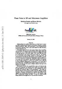
Fig. 1 Capacitive cross-coupl ing te ch niq ue The capacitive cross-coupling (CCC) has been used for gain enhancement and matching [3]. In this section, we will demonstrate how the CCC can be used to improve the NF of a common-gate input stage. Fig.1 shows the schematic of a differential common-gate input stage with CCC. It can be shown that the cross-coupling causes the noise of M1 and M2, namely v n12 and v n 2 2 , to produce common-mode noise voltages at the output node d1 and d2. Intuitively, This can be explained as follows. Let’s assume the following instantaneous polarity for noise source v n12 ; positive polarity at the gate terminal of input transistor M1 and negative at the other side (polarity can be exchanged as well). One can easily see that the drain voltage of M1 will decrease due to the positive disturbance at the gate terminal. On the other hand, because of the negative disturbance at S2, the drain voltage of M2 will also decrease. Hence, the input noise source v n12 causes a common-mode voltage at d1 and d2. Similar analysis can be applied to the input noise source v n 2 2 . A more rigorous small signal noise analysis was used for a mathematical derivation. Here, only channel
thermal noise source is considered, and other noise mechanisms are neglected for simplicity. The crosscoupling capacitors C1 and C2 are assumed to be much greater than gate-source capacitance Cgs. The derived noise factor expression of the input pair M1 and M2 is given by : F = 1+
γ 2
isolation of the LNA. Transistors M5, M6, M7, and M8 are used to realize large resistors to isolate the signal path from the biasing circuitry. The LNA’s load is a 300Ω resistance (assuming an on-chip mixer). Vdd
I bias
(2)
R1
outn VC
Worthy to mention is that the derivation of the noise factor assumes that the input impedance is matched to the source impedance for maximum power transfer. Matching for the optimal noise performance can reduce the NF value. This can be demonstrated by changing the effective input impedance (1/2×gm). Fig. 2 illustrates the change of the NF vs. the effective transconductance (2×gm). The noise performance will be improved as the transconductance is increased. Another advantage of the common gate input stage with CCC is that the input effective transconductance is doubled due to the capacitive cross-coupling. Thus, the current consumption can be reduced. Finally, it is also interesting to note that the capacitive cross-coupling does not add much cost and complexity.
M6
M9
C3
The full schematic of a LNA employing the CCC technique is depicted in Fig.3. The input impedance matching is achieved by sizing and adjusting the bias current of the input transistors M1 and M2 such that 1/(2×gm)=50Ω. The cross-coupling capacitors C1 and C2 are 10pF poly-to-poly capacitors in our implementation. Off-chip inductors L1 and L2 are used to resonate with the gate-source capacitor Cgs and the input parasitic capacitance at the frequency of interest. Cascode transistors M3 and M4 are added to improve the reverse
Inp
C1
C2
gnd
M8 M7
M2
Inn
Vdd
L2
gnd
Fig. 3 Sch e m atic ofth e LNA w ith CCC As pointed out in the previous section, the LNA with CCC provides noise advantage over the conventional differential common-gate LNA. However, the dynamic range of a circuit is not only determined by the noise but also by the linearity. Assuming that the transconductance gm is the only source which causes nonlinearity, the input referred IP3s of the conventional differential commongate LNA and the LNA with CCC are derived using volterra series. The derived expressions are given in (3) and (4), respectively.
IP 3 = 4
3. LNA Implementation using the CCC Technique
Vdd
L1
IP 3 = 8
Fig. 2 NFofth e inputpair w ith CCC vs. 2gm
M1
M5
outp
M4
M3
gnd
It can be seen that due to the capacitive cross-coupling the noise contribution from the input transistors is reduced though not completely eliminated.
R2
2 ⋅G s
(3)
3 ⋅ (− K 3 gm + K 2 gm / Gs ) 2
Gs
(4)
3 ⋅ K 3 gm
Equations (3) and (4) are simplified expressions evaluated under input matching conditions. The parameters K2gm and K3gm are the second-order and thirdorder transconductance nonlinear coefficients. Gs is the source conductance. It is observed that the IP3 of the conventional differential common-gate LNA is not only determined by the third-order nonlinear coefficient but also by the second-order nonlinear coefficient. The IP3 of the LNA with CCC is only influenced by the thirdorder nonlinear coefficient. For a first-order analysis, we may consider the MOSFET transistor to be a square-law device. This means that the third-order nonlinear coefficient is usually much smaller than the second-order one. Thus, the IP3 of the LNA with CCC is higher than that of the conventional differential common-gate LNA. Although the second-order intercept point (IP2) is not important in a heterodyne receiver, it is a limiting factor in a direct conversion receiver. The IP2 of a differential circuit is usually limited by mismatch between differential path. Assuming that only transconductance
(gm) has mismatch (∆gm) and applying the same procedure for the IP3 modeling, the input-referred IP2s of both LNAs are given by (5) and (6), respectively. 16 ⋅G s 3 K 2 gm ⋅ ∆ g 2
IP 2 ≈
(5) m
IP 2 ≈∞
(6)
Due to mismatch, the conventional differential commongate LNA shows a finite IP2, while the mismatch effect is minimal on the IP2 of the LNA with CCC.
4. Mixer Implementation using the CCC Technique Vdd IF+
Ibias
gnd
Vdd
R2
IF-
LO+ M3
M4
M5
M6
LOM1
M7
C3
C4
LO+
M8
M 11
C3
R1
RF+ L1
C1
C2
gnd
M 10
M2
M9
RF-
Vdd
L2
gnd
Fig. 4 Sch e m atic ofth e m ixe r w ith CCC In the Gilbert cell mixer, the linearity is usually determined by RF transconductance. Thus, most of the design effort is spent attempting to find better ways of providing V-I conversion. One simple, but powerful technique consists of using degeneration resistors in the source of V-I converter. But, additional resistors will penalize the mixer noise performance, which may, in turn, increase design difficulties for the circuitry preceding it. The capacitive cross-coupling technique depicted in previous sections can be used in RF V-I converter to minimize the noise contribution and improve the linearity simultaneously. The proposed double-balanced Gilbert cell mixer with CCC is shown in Fig. 4. Transistors M1 and M2, cross-coupled by capacitors C1 and C2, form a differential transconductance stage. The drain current of the M1 and M2 is steered through M3 and M4 or M5 and M6 to perform the mixing function. Output capacitors C3 and C4 combined with output resistance R1 and R2 to form a low pass filter. The purpose of this filter is to attenuate high frequency components at the IF output. Biasing of the mixer is similar to that of the LNA.
5. Experiment Results Both LNA and mixer have been implemented in an AMI 0.5µ CMOS process. Measurements of the LNA show a 12.2dB voltage gain and a NF of 3.0dB at 900MHz. The 3.0dB NF, which seems higher than recently reported values, can best be explained by the fact that the LNA was designed for maximum power transfer and not optimized for the noise figure. One can achieve better noise performance by increasing the transconductance as illustrated in Fig. 2. The gain and NF of the LNA are plotted in Fig. 5 with frequency swept from 800M to 950M. The input-referred IP3 is extracted by applying two tones test. The power of both tones was swept while the resulting third-order intermodulation product was measured. Fig. 6 shows the fundamental tone and the third-order intermodulation product at 899.5MHz and 900MHz. Since output impedance of LNA is not 50Ω, “VdBm” is defined as voltage corresponding to a power level of 0dBm in a 50Ω system. Because source resistance is 50Ω, the input “VdBm” is same as original “dBm”. The measured mixer DSB noise and conversion gain are 5.2dB and 13.2dB, respectively. The measured NF is lower than most published mixer. The results of a twotone measurement on the mixer are shown in Fig. 7. For the mixer measurement, the LO drive amplitude is equivalent to 300mV. Both LNA and mixer prototype are measured in TQFP package with ESD protection. The measured LNA and mixer results are summarized in Table.1 and Table.2 respectively. Microphotographs of both circuits are shown in Fig. 8.
6. Conclusion In this paper, we have shown how the capacitive cross-coupling technique can be used to improve the noise performance of a common-gate input stage. A LNA and mixer with CCC have been implemented in 0.5µ CMOS process to verify our theoretical findings. The LNA achieves around 3.0dB NF up to 900MHz, In addition, the LNA has significant +6.7dBm inputreferred IP3 and only consume 20mW. The mixer has very low DSB NF at 5.2dB and +13.8dBm output IP3. Yet, both circuits do not rely on using on-chip spiral inductors.
Reference [1] A. Rofougaran, J.Y-C.Chang, M. Rofougaran, A. A. Abidi, “A 1GHz CMOS RF front-end IC for a direct conversion wireless receiver ”, IEEE J. Solid-State Circuits, July 1996, vol. 31, pp. 880-889. [2] A. R. Shahani, D. K. Shaffer, and T. H. Lee, “A 12-mW Wide Dynamic Range CMOS Front-End for Portable GPS Receiver ”, IEEE J. Solid-State Circuits, Dec 1997, vol. 32, pp. 2061-2069.
[3] T. Cho et al, “A Single-Chip CMOS Direct-Conversion Transceiver for 900MHz Spread-Spectrum Digital Cordless Phones”, ISSCC Digest of Technical Papers, Feb 1999, pp. 228-229.
Tabl e .1 Sum m ary ofLNA m e asure m e nts Frequency 900MHz
Fig. 5 M e asure d LNA gain and NFvs. fre q ue ncy
NF
3.0dB
Gain (voltage)
12.2dB
IP3 (input)
+6.7dBm
IP2 (input)
+34dBm
1dB (input)
-7dBm
Power Supply
2.7V
Power Consumption
20mw
Silicon area
0.5×0.4mm2
Tabl e .2 Sum m ary ofm ixe r m e asure m e nts RF Frequency 900MHz
Fig. 6 M e asure d LNA IP3
Fig. 7 M e asure d m ixe r tw o tone te st
LO Frequency
910MHz
LO Amplitude
300mV
NF (DSB)
5.2dB
Gain (voltage)
13.2dB
IP3 (output)
+13.8dBm
IP2 (input)
+25.6dBm
Power Supply
2.7V
Power Consumption
8.1mw
Silicon area
0.7×0.5mm2
Fig. 8 M icroph otograph ofth e LNA and m ixe r