any of these other technologies, however, as neither. RAMBUS's high bandwidth nor IRAM's tightly-cou- pled processing horsepower address the timing and ac-.
Using MML to Simulate Multiple Dual-Ported SRAMs: Parallel Routing Lookups in an ATM Switch Controller Aaron Brown, Dan Chian, Nishat Mehta, Yannis Papaefstathiou, Josh Simer, Trevor Blackwell, Michael D. Smith*, Woodward Yang* Harvard University {abrown, chian, nmehta, yanni, jmsimer, tlb, smith, woody}@eecs.harvard.edu Abstract The need for fast parallel table lookups is evident in many modern hardware applications, such as network switches, hard disk controllers, and encryption devices. Typically, most of these table lookups are performed in fast and expensive on-board SRAMs in order to reduce latency. These SRAMs frequently provide dual-ported access at speeds of up to 20 ns. However, for applications demanding many large look-up tables, SRAM’s physical size, density, power requirements, and cost are prohibitive. In this paper, we address this problem through one particularly demanding example: the routing control in a sophisticated ATM switch. We present a design that uses merged memory and logic (MML, a modified form of DRAM) to simulate dual-ported SRAM in performing tens of table lookups in parallel. Our solution fits on one chip instead of over 300 required by an existing design, providing an integrated, low-power solution while still meeting the rigorous timing constraints of the application.
1 Introduction ATM networking is at the cutting edge of high-speed network technology, both in the bandwidth that it provides and in the flexibility that it offers in configuring and controlling connections (e.g., its ability to provide quality of service guarantees or bandwidth reservation). However, these features come at a price: in order to obtain control and flexibility without sacrificing bandwidth, ATM relies on expensive custom hardware for the high-speed switches that form the foundation of the network. The most advanced of these switches process tens of gigabits of data per second in the form of over 20 million 53-byte cells per second. In such switches, up to 200 table lookups are performed simultaneously by the routing control which is typically implemented with many discrete SRAMs. The increasing demand for ATM switches necessitates measures to integrate routing control and state stor*
Michael D. Smith is supported in part by a National Science Foundation Young Investigator award (grant number CCR-9457779), a DARPA grant (number NDA904-97-C-0225), and by donations from AMD, Digital Equipment, Hewlett-Packard, IBM, Intel, and Microsoft. Woodward Yang is supported in part by an NSF Young Investigator Award (MIP-92-57964), by an HPCC grant from NSF/ARPA (GC-R334138), a MURI grant from ONR (CT-S-608521), and by the Joint Services Electronics Program (N00014-89-J-1023).
age. We show that merged memory and logic (MML) offers the best technically- and economically-feasible solution to the circuit complexity, space overhead, and parts cost involved in building control for an advanced, high-speed ATM switch. Traditional solutions to integration, such as ASICs, fail in this case due to the extraordinarily high internal bandwidth of and the large amount of memory (as much as 20 Mb) needed for the control. In contrast, MML offers both the large internal storage capacity of a chip based around DRAM and the high internal bandwidth attained through the integration of routing control and state tables. However, MML introduces a host of new difficulties that must be overcome if it is to be used as the integration technology for an ATM switch’s routing controller. The first and most significant of these is speed. Our discussion is focused on a comparison to the CreditSwitch [1], an experimental switch in our lab. The SRAMs that MML would replace in an integrated version of the CreditSwitch run with a 20 ns cycle time, and many are dual-ported; achieving such a low cycle time is very difficult in a DRAM technology, and dual-porting at that speed is essentially impossible. Another significant problem introduced by the DRAM basis of MML is that of refresh: unlike the CreditSwitch’s SRAM tables, an MML-based switch’s tables require periodic refreshing to preserve the data stored within them. These difficulties are probably not entirely solvable in general. However, in our specific application, we can take advantage of certain special characteristics of ATM switching in order to neatly bypass MML’s peculiarities. The stringent timing and porting requirements of the CreditSwitch’s SRAMs are entirely a by-product of the fact that most accesses to the tables are of the form Read-Modify-Write (RMW), which typically require at least three cycles each with a traditional SRAM design. Additionally, the timing patterns of the switch guarantee that consecutive memory accesses are to different addresses. Finally, the regular patterns of an ATM switch’s operation make it possible to schedule DRAM refresh slots without interfering with normal switching operations. In this paper, we present a way of enhancing a standard DRAM block to simulate dual-porting and to handle pipelined RMW requests; because adjacent pipelined requests can never be for the same address in
our ATM application, the modified block can effectively service one RMW request per cycle. With an MML solution built from these enhanced DRAM blocks, all of the table-access requirements of an ATM switch controller can be met with a cycle time of only 33 ns, which is achievable in today’s DRAM technology. MML seems to provide the ideal solution for integrating the complex control of an advanced ATM switch, and by extension for similar problems involving parallel table lookups where RMW access patterns can be exploited. In the remainder of this paper, we demonstrate our enhancements to the standard DRAM block to allow pipelined read-modify-write accesses, and present a detailed analysis of how MML built with such blocks is ideal for the ATM switching application. In Section 2, we discuss related work in the field. Section 3 outlines our design of an ATM switch, and we conclude in Section 4.
2 Related Work A look at current memory technologies helps justify our choice of MML. Current DRAM technology is often overlooked as an implementation alternative in applications requiring multiple fast, simultaneous table lookups because of standard 1T DRAM’s high latency (30-60 ns) and single-ported design. 3T DRAM is dualported but several times larger than the typical 1T DRAM cell, and thus may not be as effective for singlechip integration. SRAM, although much faster ( 0){ active_tbl[VC] = TRUE; credit_tbl[VC] -= 1; if (al_head[pri] != NULL) { al_link[al_tail[pri]] = VC; } else al_head[pri] = VC; al_tail[pri] = VC; } cellcount_tbl[VC] += 1; }
VC_dequeue(VC, pri) { ncells = (cellcount_tbl[VC] -= 1); newhead = al_link[VC]; al_link[VC] = NULL; if (ncells == 0) { al_head[pri] = newhead; active_tbl[VC] = FALSE; } else if (newhead != NULL) { al_head[pri] = newhead; al_link[al_tail[pri]] = VC; al_tail[pri] = VC; } }
Figure 1: Pseudocode for basic ATM cell-handling operations. Cell_enqueue() and Cell_dequeue() add and remove cells from lists of queued cells, respectively. VC_enqueue() and VC_dequeue() add and remove VC’s from the prioritized lists of active VCs. See Table 2 for a description of each of the memories referenced in the pseudocode.
must be able to receive/enqueue as many as 16 cells from the input ports, and dequeue/transmit one cell to the outgoing link. In each output port’s routing control, the operations involved in receiving and transmitting cells require manipulating various state tables, as well as several linked lists. It is the linked lists that impose the greatest memory access demands. For each cell that is enqueued, the routing control must place the cell on one of 8192 linked lists of queued cells (one list for each of the 8192 supported VCs). In addition, if that linked list was previously empty, the list itself must be added to another linked list that tracks active VCs (those with enqueued cells). Similarly, when a cell is dequeued, it must be removed from its per-VC list of queued cells, and that list may have to be removed from the active VC list. The control is complicated further by the fact that there are several (32) lists of active VCs to allow for different priority classes of VCs. Each of the linked lists maintained by the routing control is either singly- or doubly-linked, and head and tail pointers are maintained for each (to allow FIFO semantics). The hardware implementation of these lists consists of several memories: a head store, a tail store, and two memories that contain the forward and reverse link pointers, respectively; these memories are summarized later in this paper in Table 2. Thus, in the CreditSwitch, each cell enqueue or dequeue operation requires manipulating, at a minimum, six separate tables to perform the two linked list operations. Simplified pseudocode for these operations is given in Figure 1 (only the linked-list manipulation is shown; the code to update the state tables has been removed for clarity).
This pseudocode shows that each enqueue/dequeue requires accesses to each of the head, tail and link memories. Notice that in most cases these accesses follow a pattern of read-modify-write (RMW) operations. For example, the enqueued-cell-list tail memory (c_tail) is first read (to index the link memory), then modified to point to Caddr, then written back. Those operations that do not require RMW can still be structured as RMW operations by either ignoring the read data, or making the modify cycle a no-op. Although not shown, all of the state table updates can be structured as RMW operations as well. We structure all memory operations as RMWs in order to produce a simpler memory design for our implementation, since in this case all the memories can be identically-structured. Finally, since the CreditSwitch operates under the constraint that no two incoming cells destined for the same output port in the same cell cycle can be on the same VC, no memory address will be used for more than one RMW operation per cell cycle.
3.2 An MML Implementation of ATM Routing Control We now consider how to adapt the design of the CreditSwitch’s routing control to an integrated MML design. Note that we are considering only the control in this paper; the datapath for the cell data payloads can be implemented either with traditional DRAM or SRAM, or with an IRAM/MML design [3]. The control circuitry processes only the cell headers, which comprise 1.4 Gb/s of external bandwidth. Internally, under worstcase traffic load, nearly 5,000 bits of control memory in the CreditSwitch are accessed every cell cycle (694 ns) for a raw internal bandwidth of 6.7 Gb/s of mixed reads
and writes. The CreditSwitch attains this internal throughput with commodity parts by using 272 highspeed SRAM parts (208 of which are dual-ported), 17 for each of the 16 ATM ports, plus at least 48 EPLDs for control. The total amount of memory devoted to state tables approaches 20 Mb. This circuitry is not only extraordinarily expensive but incredibly complex. There are two reasons why the CreditSwitch relies on so many discrete dual-ported SRAMs. The first is simple: the amount of table storage used in the routing control (approximately 20 Mb across the 16 ports) is too large to fit on a single ASIC. The second is more subtle: in order to pipeline cell enqueue and dequeue operations, the various linked-list memories must be both read and written in the same clock cycle. Since the circuitry implementing the modify operation is separate from the SRAM storage on the CreditSwitch, dual-ported SRAMs are required. In contrast, MML provides both a large internal memory (via its DRAM technology) and the capability of integrating the modify-logic onto the same chip as the memory. However, to replace the CreditSwitch’s dualported SRAM with DRAM, we must overcome two limitations of DRAM: its relatively large access time and its refresh demands. We can take advantage of both the flexibility of MML and the RMW-structure of the CreditSwitch’s operations to solve both of these problems and thus construct an integrated version of the CreditSwitch’s routing control.
be structured as RMW operations. A cell enqueue operation requires one RMW per cell-list head or tail memory; the corresponding VC enqueue operation can require one RMW per active-VC-list head or tail memory. Both dequeue operations are more complicated, since it is necessary to access the link memory (which will take at least one full memory clock cycle) between reading an entry from the head memory writing it back. This access pattern to the head memory can be implemented as two RMWs: during the first RMW, the read data is written back without modification, and during the second, the read data is ignored and the appropriate value is written back. Thus a dequeue operation can be implemented using the equivalent RMW operations as two enqueue operations. Our circuit will use a clock running at approximately 30 MHz, and thus a clock cycle of just over 33 ns. This allows us 21 clock cycles per 694 ns cell cycle. To implement all control processing in 21 clock cycles, each of the 16 enqueue operations is staged into 3 pipelined phases so that different phases of contiguous enqueue operations can be executed at the same time. Because dequeue operations can be implemented similar to two enqueue operations, we perform in total the equivalent of 18 enqueues through a 3-stage pipeline. Finally, since refresh cycles can also be structured as RMW cycles with a null modify stage, the remaining 3 pipeline slots can be used to refresh the DRAM memories. We avoid data inconsistency problems between refresh cycles and pending enqueue/dequeue operations by detecting duplicate addresses and bypassing the refresh, or by servicing the refresh read out of the data latches rather than the DRAM bank itself. The reason for these pipeline hazards and the bypassing technique are described in Section 3.2.3. By using the free pipeline slots for refresh, the maximum time between refresh for any entry in the largest memory (c_link) is at most 60 µs. Table 1 shows how each of the routing control memories is used during each of the 21 total clock cycles.
3.2.1 A RMW Pipeline for Cell Operations To accomplish this, we have created a new pipeline design that allows the required 16 enqueue and 1 dequeue operations (per-port) to be implemented entirely in the form of pipelined RMW operations, with the exception of the first read in cell_dequeue(), which is optimized into a single memory read. As we saw in the pseudocode above, all of the memory accesses made in the CreditSwitch’s routing control can
Memory
Memory Usage in Each 33 ns Clock Cycle (0–20) 0
2
3
4
5
6
7
8
9
10 11 12 13 14 15 16 17 18 19 20
E0
Dβ
E1
E2
E3
E4
E5
E6
E7
E8
E9
E10 E11 E12 E13 E14 E15
al_tail
E0
Dα
E1
E2
E3
E4
E5
E6
E7
E8
E9
E10 E11 E12 E13 E14 E15
al_link
Dα
E0
Dβ
E1
E2
E3
E4
E5
E6
E7
E8
E9
E10 E11 E12 E13 E14 E15
E1
E2
E3
E4
E5
E6
E7
E8
E9
E10 E11 E12 E13 E14 E15
E3
E4
E5
E6
E7
E8
E9
E10 E11 E12 E13 E14 E15 E10 E11 E12 E13 E14 E15
al_head
Dα
1
Dα
cellcount credit_tbl
E0
E0 E1
E2
active_tbl
E0
Dα
E1
E2
E3
E4
E5
E6
E7
E8
E9
c_head
E0
E1
E2
Dα
E3
E4
Dβ
E5
E6
E7
E8
E9
E10 E11 E12 E13 E14 E15
c_tail
E0
E1
E2
E3
E4
E5
E6
E7
E8
E9
E10 E11 E12 E13 E14 E15
E2
Dα
E5
E6
E7
E8
c_link
E0
E1
E3
E4
E9
E10 E11 E12 E13 E14 E15
Table 1: Memory Usage in Routing Control Memories. This table shows how each RMW access to a routing control memory is scheduled in the 21 33 ns pipeline slots available in each cell cycle. Each entry represents the time when a RMW operation is initiated; each operation continues for two additional cycles before completing. The slots marked “E x” represent a RMW involved in enqueuing cell x; Dα and Dβ represent the two RMWs involved in dequeuing a cell. Empty slots in the pipeline are used for refresh. Note also that, since al_head is implemented via a register file (see Table 2), the data from Dα is available as needed in cycle 1.
Thus, by using the RMW pipeline, we are able to accomplish the required number of enqueues and dequeues, while still using a cycle time that is long enough to be attainable in MML’s DRAM process. Additionally, as we will see in the next section, this pipeline is well-suited for an MML implementation, as the DRAM blocks in MML can be modified to support the simultaneous reads, modifies, and writes required by the pipeline.
3.2.2 Modifying MML’s DRAM Block to Implement the RMW Pipeline Because every table operation can be reduced to a RMW, we have tightly coupled our RMW pipeline design with our DRAM blocks. Our pipeline has three phases, each requiring one clock cycle: the address decoding phase, the read phase, and the modify and write phase. Implementing this pipeline in DRAM requires that the memory blocks be capable of simultaneously performing a decode on one address, a read on another address, and a write on a third address. Standard DRAM blocks cannot meet these access criteria, and thus we have developed modifications to the basic DRAM block structure to permit an implementation of our pipeline design. We begin by duplicating all the peripheral circuitry of the memory banks: our modified DRAMs have two address decoders, two latch/ drive blocks, and two modify blocks (the logic that performs the modification in a RMW cycle). We will refer to these groups of circuits as components A and components B. We use a 1-bit counter to determine which set of components are used during each clock cycle. We also alter the timing of the DRAM to make it possible to perform one read and one write operation in the same clock cycle. Finally, we add two pipeline registers, one for each group of circuits, between the address decoders and the DRAM block; these hold the decoded addresses for use in later cycles of the pipeline. These registers cannot be implemented as traditional SRAM blocks, since they must be pitch-matched with their corresponding DRAM cells (1µm in height). In order to deal with this problem, we propose a design for the basic cell of these pipeline registers in Figure 2. The original CreditSwitch required dual-ported memories because its design often mandated a read and a write to the same memory in one 33 ns clock cycle; our pipeline has a similar constraint. Since our design allows us to enhance the basic structure of a DRAM block, we use the following tricks to simulate dual-ported SRAM within our MML-DRAM design, as shown in Figure 3: • Use two row address decoders instead of one found in standard DRAMs. • Use two column address decoders instead of one found in standard DRAMs. • Latch the output of these decoders so that is can be used in subsequent clock cycles.
• Use two sets of output latches and drivers, instead of one found in standard DRAMs. • Split up the memory into 128 x 256 blocks, so as to reduce the time required to drive the bit and the word lines. Table 2 shows how each output port’s table memory is divided into these blocks. In addition to the above we implement two circuits that do the modification part of the RMW operation and a simple finite state machine (Cnt) for determining which set is active during every clock cycle. Each of these circuits is associated with one particular set of the memory’s peripheral circuit. It is activated along with the corresponding set of memory drivers in the same clock cycle. CLK
A1
SRAM (Register) Cell
A1
SRAM (Register) Cell
A0
SRAM (Register) Cell
A0
SRAM (Register) Cell
Enable
WordLine0
WordLine1
SRAM (register) cell
WordLine3
WordLine4
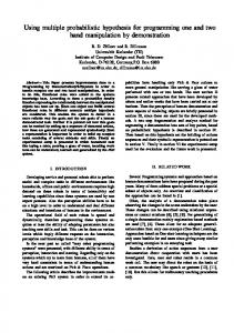
Figure 2: Pipeline Register Implementation (not to scale): These registers store the last decoded address. In order to satisfy pitch-matching constraints, we use one SRAM cell for every four cells of DRAM memory, one 2-input NAND gate for every two DRAM cells, and one pass gate (2 NMOS transistors) per DRAM cell. The four AND gates allow us to tristate the word lines. Although this circuit requires driving a word line through a pass gate (a potentially slow method of asserting a word line), this is the way the word lines are driven in many commercial DRAM chips.
Enable_Right
Word Line
Enable_Left
Cnt
DRAM Cell
Renable (decoded MS bits IVC[8:7])
Renable (decoded MS bits IVC[8:7])
Vref Vdd
Vref
Word Lines
Word Lines
Precharge
IVC[6:0]
Bit Line Precharge
Precharge Circuit
PhiL
IVC[6:0]
DRAM Block
RdecA R e g A
R e g B
Sense Amplifier
RdecB PhiS
Read * right_enable | Right_bypass
SRAM (Register) IVC[16:9]
IVC[16:9] Column_enable
Sense Amplifiers
Out * left_enable
CmuDecA
CmuDecB Write * right_enable Column_enable
Latches, Drivers, Modify Circuits
Modify Circuit
Read * left_enable | Left_bypass
SRAM (Register) Output
Latches, Drivers, Modify Circuits
Column_enable Out * right_enable Write * left_enable Column_enable
Modify Circuit Caddr or c_link[IVC] (input) c_head[IVC] (output)
Caddr or c_link[IVC] c_head[IVC] (input) (output)
Input
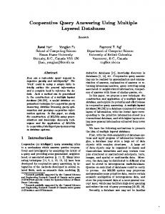
Figure 3: Diagram of Basic Memory Block. The DRAM block is an ordinary 32 Kbit DRAM array, structured as a 128 x 256 bit array. The sense amplifiers are unmodified. RdecA and RdecB are decoders that drive the word lines. CmudeA and CmudeB are column multiplexors/demultiplexors. RegA, RegB, are pipeline registers used for storing the outputs of the decoders and the multiplexors/demultiplexors which are used in the other phases of the pipeline. The two sets of latches, drivers and modify circuits latch the output data of the read phase, and modify and write the output data on the write-modify phase of our pipeline. Finally, the cnt counter is used to determine which set of components is activated every clock cycle. A bit slice of the circuitry at the bottom of the DRAM block is shown on the right; note in this diagram that each “out” signal (one for each latch) is ANDed with the opposite enable signal (the signal for the other latch) to allow reading from one latch while the other writes its data into the memory. See the timing diagram in Figure 4 for more details on the sequencing of these signals.
Group
Use of Memory
Size
Memory Layout
Table of Active VC Lists
Head Memories (al_head) Tail Memories (al_tail) Status of list (status)
32x14 32x14 32x1
Register File Register File Register File
Lists of Active VCs
Link Memories (al_link)
8Kx14
4 Blocks
Credit Count (credit_tbl) Cell Count (cellcount_tbl) Flags Active List ID Head Memories (c_head) Tail Memories (c_tail)
8Kx8 8Kx8 8Kx2 8Kx6 8Kx16 8Kx16
2 Blocks 2 Blocks 1 Block 2 Blocks 4 Blocks 4 Blocks
State per VC
Per-VC Queues of Cells Lists of Queued Cells
Link Memories (c_link)
32Kx16
16 Blocks
State per Queued Cell
Ownership Memory
32Kx4
4 Blocks
Table 2: Per-Port Memory Usage within Switch. For each port, our design requires 39 128x256 bit blocks (and three register files), for a total of 1248 Kb per port. To implement a 16-port switch requires 19.5 Mb, allowing us to implement our design in either a 32 Mb or 64 Mb DRAM process with enough space for logic. The entire switch also requires one master routing table of 8Kx40, using an additional 352 Kb of memory (11 blocks).
7ns
Precharge 4ns
Read Word Line, Read
1ns
9ns
Sense Amplifiers 4ns
Write Word Line, Write, Out
8ns
Bit Line Drivers 3ns
Column_Enable
8ns
Bypass (if needed) Figure 4: Overview of Signal Timing for RMW-optimized DRAM. The modified DRAM operates with a cycle time of 33 ns; in each cycle, the memory is both read and written, as can be seen in the timing diagram. Note that the read and write are in most cases for different rows, with the two addresses coming from the decoder latches shown in Figure 3.
3.2.3 Memory Timing The data flow and organization in our pipeline is the following; an overview of the signal timing is presented in Figure 4: • Use a counter to determine whether we are using the A or the B component set. Without loss of generality, let us assume that we use the A set. • In the first clock cycle, we decode the row and column address, writing the results in the corresponding pipeline register. • In the second clock cycle, activate the appropriate word line to read the desired data from the memory. Enable the sense amplifiers, latch the row of data, and use the decoded column address to enable the outputs corresponding to the portion of the row that contains the data that we actually want. • In the third clock cycle, first modify the previously read data. Then reactivate the appropriate word line (the same one used in the second clock cycle). Finally, drive the word lines so as to write the actual data back in the memory. This pipeline has several subtleties. First, due to the overlap between adjacent operations, we attempt to perform both a read and a write-modify to the same memory (at different addresses) in one clock cycle. To achieve this, we take advantage of the fact that a DRAM write operation can be done without first precharging the bit lines. Instead, we can simply drive the bit lines with the desired values. Another subtlety arises from the size of the DRAM blocks. We have split our DRAM into small blocks (128 x 256 bits) to yield shorter bit and word lines, allowing us to drive them faster. However, since our widest tables are only 16 bits wide, we must place several table entries in each line of DRAM to efficiently use the blocks. With
this change, our assumption that different RMW operations are at different addresses no longer holds, since different table addresses can map to the same DRAM line. As a result, data inconsistencies are possible if an operation reads data at a given address before the prior operation writes back modified data at that same address. To solve this problem, we introduce some extra circuitry to detect duplicate addresses and, in that case, to service the second operation’s read from the latches holding the modified data from the first operation. In other words, if we see that the second RMW falls in the same row as the first one, we wait until the data from the first RMW are driven into the bit lines, then enable the bypass signal seen in Figure 4, allowing the data to be latched by the second set of row latches. By doing so, no overwriting of data is possible. Finally, the modifications we made to avoid data inconsistency allow us to insert memory refreshes (structured as RMWs with a null modify) at any free pipeline slot without the fear of writing back inconsistent data. Since each memory has at least three open slots, we can refresh three lines every 694 ns; each memory block is 256 lines long, so if they are refreshed in parallel, the entire memory can be refreshed once every 60 microseconds. Note also that the main routing table (which routes incoming cells to the appropriate output port for queueing) can be refreshed in a similar amount of time. Notice that the timing presented in Figure 4 is in fact very conservative. We can see why this is true by comparing our timing with that of a standard 64 Mb DRAM, which is the technology upon which we have based our calculations. The 64 Mb DRAM uses basic blocks of size 256 x 512. In this basic block the length of a word line is approximately 500 µm and the width approximately 0.4 µm. The resistance per square µm of
the polyside used for the word lines is 12 Ω/µm2. So in their case the total resistance of the word line is (500 µm / 0.4 µm) ∗ 12 = 15KΩ. The capacitance of this line is 0.25 pF and so the RC delay of the word line is 15 KΩ ∗ 0.25 pF ≈ 3.75 ns. The specified time to assert the word line is approximately 9 ns, which includes a safety margin of about 2.5 times. In our MML design, we have 128 x 256 bit basic blocks. Since our word lines are half the length of those found in 64 Mb DRAM, both their resistance and capacitance are correspondingly reduced by a factor of two. As a result, the time needed to assert a word line is about four times smaller in our design than in standard DRAM. Therefore, we can conceivably assert our word lines in only 2.5 ns. We have allotted 4 ns, as seen in Figure 4. Additionally, we have allowed 1 ns for the deassertion of the word line, which is a sufficient amount of time to lower the word lines through one NMOS transistor to the threshold voltage. We can lower the lines to 0 Volts during the time that another bit line is open (in other words we can have some limited overlapping between the assertion of the write word line and the deassertion of the read word line). Similarly, standard DRAM requires 15 ns to securely precharge the bit lines. Once again, we have a two-fold reduction in size, which creates a four-fold reduction in precharge time, resulting in a minimum precharge of about 4 ns for our design. As can be seen in the timing diagram, we have allotted 7 ns. In the case of a write, ordinary DRAM allows 25 ns to drive the bit lines; since our bit lines are half the length, we need only 25/4 ≈ 6 ns, and we allocate 8 ns. Finally, we allocate the same amount of time to the sense amplifiers as does standard 64 Mb DRAM (9 ns). Notice that we have allowed large safety margins in our timing as compared to standard DRAM. If these safety margins are reduced, our design is capable of sustaining a memory cycle time of 22 ns, or a 45 MHz clock. Additional hardware changes to implement twostage sense amplifiers would allow the clock to rise to 59 MHz; the first stage would be decoupled from the word lines after 3 ns and the second stage would take over. However, neither of these enhancements is necessary for our ATM switch application.
4 Conclusion The main benefit of integrated DRAM and logic (MML) is the potential for relatively high internal memory bandwidth on a single chip. Many applications involving frequent table lookups or hardware linked-list manipulations can benefit from this high internal bandwidth. It was in researching one potential application of this advantage of MML, ATM switching, that we discovered a second advantage: the ability to simulate SRAM-like latencies and emulation of dual-ported SRAM with DRAM. Being able to place logic on a DRAM chip enables the use of more complicated memory structures—such as the special memory we have
described in this paper. Using these techniques we can further increase the internal bandwidth and decrease the latency of on-chip memory. We have examined the significant effects this can have for a proposed ATM switch. There are many other applications for which it could be useful, such as harddrive controllers and encryption devices. For the ATM switch, we are able to replace a device that uses over 300 separate chips with a single cheaper chip without a performance loss, and we expect similar gains can be made in other applications as well. In short, by integrating logic with memory, we have shown that with certain assumptions, one can replace SRAM with integrated DRAM and retain the best of both worlds.
5 References [1] Blackwell, T., K. Chan, K. Chang, T. Charuhas, B. Karp, H.T. Kung, D. Lin, R. Morris, M. Seltzer, M. Smith, C. Young, O. Bhagat, M. Chaar, A. Chapman, G. Depelteau, K. Grimble, S. Huang, P. Hung, M. Kemp, I. Mahna, J. McLaughlin, M.T. Ng, J. Vincent, J. Watchorn. “An Experimental Flow-Controlled Multicast ATM Switch.” Proceedings of the First Annual Conference on Telecommunications in Massachusetts, 1994. [2] Blackwell, T., K. Chang, H.T. Kung, and D. Lin. “Credit-Based Flow Control for ATM Networks.” Proceedings of the First Annual Conference on Telecommunications in Massachusetts, 1994. [3] Brown, A., I. Papaefstathiou, J. Simer, D. Sobel, J. Sutaria, S. Wang, T. Blackwell, M. Smith, and W. Yang. “An IRAM-Based Architecture for a Single-Chip ATM Switch.” Technical Report TR-07-97, Center for Research in Computing Technology, Harvard University, 1997. [4] Patterson, D., T. Anderson, N. Cardwell, R. Fromm, K. Keeton, C. Kozyrakis, R. Thomas, K. Yelick. “A Case for Intelligent RAM: IRAM.” To Appear in IEEE Micro, April 1997. [5] Rambus, Inc. “RAMBUS and UMA: The Win/ Lose Debate.” http://www.rambus.com/docs/uma.pdf. [6] Rambus, Inc. “Rambus Memory: MultiGigabytes/Second and Minimum System Cost.” http:// www.rambus.com/docs/mpf96.pdf, 1996.