Using the Integrated Notation for Defining Product Line Architecture Mar´ıa Cecilia Bastarrica 1 , Marcelo L´opez1 , Sergio F. Ochoa1 , and Pedro O. Rossel2 1
Computer Science Department, Universidad de Chile, Blanco Encalada 2120, Santiago, Chile, {cecilia,sochoa,mlopez}@dcc.uchile.cl, 2
Departamento de Computaci´ on e Inform´ atica, Universidad Cat´ olica del Maule, Av. San Miguel 3605, Talca, Chile,
[email protected]
Abstract. The use of the Software Product Line (SPL) approach has allowed the reduction of the development effort of software products and also the improvement of product quality. The Product Line Architecture (PLA) is one of the most important assets in a SPL. Usually, well defined PLAs require a high level of formality. Thus, in scenarios where the designers are not very familiar with formal notations, the formal specification of PLAs becomes an activity very difficult to carry out. Although there are some notations for specifying PLAs, these notations require the designers to have strong skills in formal methods. In order to complement the set of available solutions to specify PLAs, this paper shows how the Integrated Notation for software architectures could be used for the formal specification of PLAs, without overwhelming developers with notation, while still allowing them to clearly identify variations and versions. The formalization of a PLA for data middleware is used as an example to show the capabilities of the Integrated Notation as a specification tool in this kind of scenarios.
Keywords: Product Lines Architecture Definition, Software Product Lines, Data Middleware.
1
Introduction
The Software Product Line (SPL) approach towards software development promotes a big improvement in productivity and software quality, as well as a reduction of the risks involved in the development process [7]. However, a SPL requires a big investment in the development of robust and good quality reusable assets. Reusable software components are important, but defining a reusable PLA has a potential higher impact on the whole SPL provided that it is shared by all
products. This is a big challenge because this PLA needs to be precise enough to clearly define the architecture of each product in the SPL, and flexible enough to accommodate variations and versions among different products. A good design of a PLA is almost as important as a good specification, because if the PLA is not well documented it may not be well understood, used and maintained. Informal specifications are easier to develop, but they have all the drawbacks ambiguity brings. On the other hand, formal specifications promote the possibility of analyzing architectures, but they can also overwhelm developers with notation details. There are currently notations for software product lines, which can be used to support the formalization of PLA specifications. However, these notations generally require the designers to have strong skills in formal methods. In scenarios where the designers are not familiar with formal notations, the formalization process of a PLA may become an activity hard to carry out. In order to complement the set of available solutions to specify PLAs, this paper shows how the Integrated Notation for software architectures [3] can be used in the specification of PLAs. This notation allows designers to work in three levels of abstraction and formality for specifying a PLA: structure, dynamics and domain specific abstract data types. Separation of concerns in different abstraction levels helps dealing with complexity and makes it easier to identify commonalties and variations among products in a SPL. The Integrated Notation uses three levels of abstraction to specify architectures and confines variations to the ADT specification. The specification of a PLA for data middleware is presented as an example showing the capabilities of the Integrated Notation as a specification tool. Next Section presents and analyzes some related work. Section 3 introduces the Integrated Notation to specify software architectures. Section 4 describes the PLA for data middleware using the Integrated Notation. Finally, Section 5 presents the conclusions and work in progress.
2
Related Work
One well-known proposed notation for specifying product line architectures is KobrA. The KobrA method 3 has been developed at the Fraunhofer Institute for Experimental Software Engineering (IESE) and provides a common and integrated viewpoint on several IESE works on product line engineering [1, 4]. KobrA, which is based on PuLSE (Product Line Software Engineering), represents a synthesis of several advanced technologies including: component-based development, frameworks, architecture-centric inspections, quality modeling and process modeling. As a general-purpose method, KobrA defines the product to be produced in a software development project and the recommended process for creating it. Although, KobrA has shown to be useful to define SPL, it is limited to specify architectures because it is based on UML, and UML, at least until 3
KobrA is a German acronym (Komponentenbasierte AnwendungsentwicklungsMethode) that stands for ”Component-based Application Development method”.
its current standard version [12], is intended for object-oriented systems while the architectural modeling represents component-based systems. In addition, UML models classes, objects and invocations while the architectural modeling requires to specify components, connectors and configurations. These are some of the reasons why UML based notations are not well suited to specify software architectures. UML 2.0 [13, 14], with its new ports primitives, promises to deal with architectural issues in a more appropriate way. Other interesting notations for specifying product line architectures are Koala and Mae. Both have considered that a PLA is a normal software architecture that contains several well-defined variation points. For this, both have created special language features [8]. The high level of formality involved in these languages requires that designers modeling and specifying the PLA have strong knowledge on formal software specifications. This requirement limits the use of these languages. On the other hand, an Architectural Definition Language (ADL) called xADL 2.0 provides an alternative to specify PLAs [9]. This ADL consists of a set of core XML schemas that capture the basic elements of a product family architecture. The three elements of a product family representation, namely versions, options and variants, are provided as independent extensions to a set of schemas that define a normal software architecture [8]. Even though it is widely accepted that an architectural specification should include multiple views [6], xADL is not able to separate the specification of the structure and dynamics of a PLA.
3
Integrated Notation for Software Architecture Specification
There is no standard notation for defining software architectures. Many ADLs have been proposed for several different application domains, but there is still no evident convergence towards one way or other for formalizing software architecture definition [10]. Generally, intuition in software architecture specification does not go together with formality, and the more formal a specification is the more difficult it is to develop and understand. A good architecture specification should be expressive and understandable so that it can guide a development team in building the product. The Integrated Notation provides the expressiveness to allow architects to formally specify components, connectors, interactions and interfaces in a direct and unambiguous way. The specification of a product line architecture should have the qualities required from any architecture specification. It must also be flexible enough to be able to adapt to different products both planned and unexpected, being able to model the concepts of variations and versions. The integrated notation for specifying software architectures [3] can be used to address these requirements. This notation reuses already existing notations for defining structure, behavior and domain specific ADTs in three different levels of abstraction. It addresses the architectural specification from a component and connector viewtype perspective [6].
For each specification level a particular language already defined is used. Boxand-line diagrams are used for specifying structure, Input/Output Automata [11] for behavior, and Larch traits [15, 16] for ADTs. IOA and Larch are naturally integrated because IOA was created assuming Larch definitions available. The integration of structural and behavioral specifications is also presented in [3]. Even though IOA was not created as an ADL, in [2] it is shown that it provides most of the features required from an ADL to be considered as such [20]. The graphical box-and-line specification level on top of the two textual specification levels promotes understandability and intuition for architectural structure, but its usefulness is more in the process of developing the specification than as part of the final formal specification. As the integrated notation separates the specification of structure, behavior and data types, it can help accommodate the specification of variations in a software product line. In the data middleware PLA used as an example, the structure and interaction behavior was found to be common, and thus reused for all products in the SPL. Only the ADTs used in each product needed reimplementation, as will be shown in Section 4. The separation of concerns of the Integrated Notation allows developers to deal more clearly with variations in a SPL architecture formal specification, while providing a strong theoretical background for analyzing specifications. Next Section presents the specification of a PLA for data middleware, using the integrated notation, in order to show the capabilities of such notation as a PLAs specification tool.
4
Data Middleware PLA
A data middleware is a software system in charge of getting the information generated by a legacy application, filtering it, transforming it and storing it so that it can be used by another independent application. Usually, each couple of applications that need to interchange data uses a different data. Therefore, many different data middleware are developed each year, therefore, it is naturally to think of data middleware as a SPL. Data middleware applications are generally strategic for organizations because they allow new applications to use data of legacy systems without the need to dig into implementation details. The SPL approach promotes the possibility of generating this kind of applications in a faster and more reliable way. The development of data middleware products is not necessarily a complex task, but it requires a very careful work. A mistake in the way data are translated could mean many troubles and losses for an organization. Typically, the quality of the information, provided as a result of a translation and the performance of the translation process, are major concerns for the developers. For the last two years the authors have experimented with SPL concepts to support data middleware development. First, an informal product line architecture was deduced from two applications already developed. Then, this same architecture was applied in a third system, and validated in a fourth one [18]. Section 4.1 describes the applications that were used to deduce the PLA, and
those that were faced starting with the PLA as the only reusable asset. Section 4.2 describes in detail, yet informally, this architecture, and Section 4.3 shows how it can be formalized using the Integrated Notation. 4.1
The Applications
Two years ago the authors started applying some of the concepts involved in SPL development as an academic exercise. After realizing that two of the latest developments in a software development company involved data transformation from a legacy application to be used in a new unplanned product, the authors developed a general architecture that would suit this class of systems [17]. The product line architecture was more a general draft of an architectural pattern than a well-defined architecture. With the experience of building the first two systems it was possible to realize that data middleware applications had a series of characteristics that needed to be taken care of: – The frequency of the data production and consumption is usually different, so extraction from legacy 1 and making data available for legacy 2 should be independent. – The format and aggregation of data is generally different, even though data used in legacy 2 must be consistent with that produced in legacy 1. – Not all the information available in legacy 1 is relevant for legacy 2. Soon after the first SPL architecture was proposed, the company was asked to develop a third data middleware system. The development was faced with the sketched architecture as a roadmap. All required components were identified, however none of them were available for reuse. Table 1 describes the four data middleware applications considered. The first two were built from scratch, with no concept of SPL in mind, and they were used to deduce a PLA. The last two applications were developed with the SPL architecture described in Section 4.2 as the only reusable asset.
Number Description Takes data from a transactional database, filters it and aggregates it so 1 that it can be used in a data warehouse. Extracts information from a transactional database and transforms it to 2 be published on the web. 3 Migrates data from a data warehouse to another one. 4 Communicates data from a transactional legacy system to SAP modules. Table 1. Data middleware applications
4.2
The Software Product Line Architecture
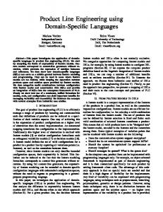
The product line architecture was first defined as a structure of boxes-and-lines as depicted in Figure 1 nearly following a pipes-and-filters pattern [5]. In Table 2 a brief explanation of each type of component in the architecture is provided.
LEGACY 1
SCHEDULER 1
CONSTRUCTOR 1
READING 1
FILTER 1
TRANSFORM 1
SCHEDULER 2
SAVING 1
INTERFACE
CONSTRUCTOR 2
READING 2
FILTER 2
TRANSFORM 2
SAVING 2
LEGACY 2
Fig. 1. Architectural structure of the data middleware SPL
There are components with similar names such as CONSTRUCTOR 1 and CONSTRUCTOR 2, or FILTER 1 and FILTER 2. Even though they have similar functionality, they execute independently and they have different timing. They are different instantiations of the same component types that may also be parameterized with different data types. Applying the proposed defined architecture as the only reusable asset, a reduction of 25% in the development time was obtained [19]. However, not having the identified components formally specified created ambiguities that could have been avoided. A formal definition of the PLA would allow determining if an instance of a component type, already developed as part of a former application, could be directly reused in a new application, or if a new version of it was needed. If a component has the same input and output actions, and uses the same data types, then it could be directly reused. If, on the other hand, it has the same interface but it manages different data types, then part of it
Component LEGACY 1 SCHEDULER CONSTRUCTOR READING FILTER TRANSFORM SAVING INTERFACE LEGACY 2
Description Independent application where data is produced. Determines the schedule when extraction takes place. Checks for the availability of the data sources. Reads data from the sources. Selects the relevant information. Puts data in the appropriate format. Saves the data in a place where it is available. Intermediate data storage. Independent application that uses the transformed data. Table 2. Component description
should be re-implemented. Only having this documentation about components makes it possible to make sound decisions and probably achieve more benefits in development effort savings due to component reuse. 4.3
Formalization of SPL Architecture
The informal product line architecture of the data middleware shown in Figure 1 can be considered as the structural specification of all applications in the SPL. So, according to the integrated notation, in order to have a complete specification, the behavior and the ADT specifications are the only missing parts. Figure 2 shows a possible specification of a FILTER component type and Figure 3 a possible specification for a TRANSFORM component type. Note that these components are specified as IOA automata that are parametric in the type of data they receive and send: Data and NewData. These types can be defined as domain specific ADTs using Larch, as shown in Figure 4. FILTER receives some data and stores it in a buffer, afterwards it filters these data selecting some pieces of information and putting them in an output buffer. Separating the operations of data that have been read, selecting and sending filtered data allows FILTER to process data incrementally without loosing information, independently of the type of data being selected. Alternatively, only one buffer could have been used, selecting the relevant data to be stored as part of the input transition effects; then, the internal transition would not be necessary. All FILTERs will have the same interaction behavior in all data middleware applications; the only thing that changes is the criterion used for the selection of the relevant data (the relevant operator). The Integrated Notation allows the architect to confine this operation as part of the Data specification and implementation (see Figure 4). The TRANSFORM components receive a piece of Data as an input (filtered data) and transform its structure so that it has a new format: NewData. This transformation is represented as an operator of the NewData specification: transform (see Figure 4).
automaton FILTER (Data : type) signature input read data (d : Data) internal select output filtered data (d : Data) states buffer in : seq[Data] := {} buffer out : seq[Data] := {} transitions input read data (d) eff buffer in := buffer in ` d internal select pre buffer in 6= {} eff if not empty(relevant(head(buffer in))) then buffer out := buffer out ` head(buffer in); buffer in := tail(buffer in) fi output filtered data (d) pre buffer out 6= {}; d := head(buffer out) eff buffer out := tail(buffer out)
Fig. 2. IOA Specification for FILTER
The specification of the whole system is the parallel composition of the instantiation of each of its component types. This composition is a common IOA operation. The dynamics of the execution is as follows: whenever a transition is executed in an automaton, all transitions with the same name within the composition are also fired atomically. In the case of the Data Middleware PLA, filtered data is an output transition for FILTER and an input transition for TRANSFORM. A piece of data of type Data is sent in this message. The TRANSFORM automaton then changes the structure or representation of the data and stores it internally as a sequence of a new type of data: NewData, that will eventually be sent out by the output transition transformed data.
automaton TRANSFORM (Data, NewData : type) signature input filtered data (d : Data) output transformed data (nd : NewData) states buffer : seq[NewData] := {} transitions input filtered data (d) eff buffer := buffer ` transform(d) output transformed data (nd) pre buffer 6= {}; nd := head(buffer) eff buffer := tail(buffer)
Fig. 3. IOA Specification for TRANSFORM
Data: trait Structure tuple of id: Identifier, mark: Del Mark, field 1:Type 1, NewData: trait field 2:Type 2, NewStructure tuple of id: Identifier, mark: Del Mark, . . field 1:Type 1, . field 2:Type 2, field n:Type n Dt S tuple of field 1:Type 1, . . field 2:Type 2, . field m:Type m . . includes . Data, field n:Type n Set(NewDt for C, NewStructure for E) includes introduces Set(Dt for C, Structure for E) transform: Dt → NewDt introduces insert: NewStructure, NewDt → NewDt create: → Dt exist target: NewDt → Bool insert: Structure, Dt → Dt empty target: NewDt → Bool empty: Dt → Bool empty source: NewDt → Bool start: Dt → Identifier start: NewDt → Identifier final: Dt → Identifier final: NewDt → Identifier counter: Dt → Int counter: NewDt → Int read: Identifier, Dt → Structure read: Identifier, Dt → NewStructure order: Dt S, Dt → Dt remove: NewDt → NewDt relevant: Dt → Dt asserts asserts ∀ s: NewStructure, d: NewDt ∀ i: Identifier, s: Structure, d,d’: Dt empty target(insert(s,d)) == false; empty(insert(s,d)) == false; empty target(remove(d)) == true; empty(relevant(create)) == true counter(remove(d)) == 0 counter(create) == 0 ; counter(insert(s,d)) == if s 6∈ d then counter(d) + 1 else counter(d)
Fig. 4. Larch Specifications for Data and NewData
Providing different implementations for Data and NewData we can get different products of the Data Middleware SPL all sharing exactly the same IOA specification.
5
Conclusions
Data middleware are common applications, so treating them as SPL is natural, and in our experience it has shown to be useful [17]. In order to get still more benefits of the SPL approach, by setting the conditions for component reuse and the possibility of increasing quality through specification analysis, this paper has shown how to use the Integrated Notation as a means of formalizing the PLA of a data middleware SPL. For the specific case of data middleware, it was found that all applications in the SPL shared the structure and the component interaction behavior, and that variations could be confined to data type implementations. In this way, the separation of concerns promoted by the Integrated Notation, helped in the process of identifying and localizing variations and thus supports the decision making about component reuse.
Even though developing the complete specification of the PLA using the Integrated Notation still requires high skills in formal methods, this requirement is only for the architect. Developers participating in the project should only understand the structural box-and-line diagram and the specification of the particular component of data type that they will be implementing. In the software project mentioned in the paper, developers were able to develop this understanding in a period so short that did not affect the whole project schedule. Specifying the data middleware as a SPL is a first step towards conceptualizing it as an architectural pattern. While SPL allows big gains in productivity by massively reusing assets, the architectural pattern for data middleware will provide a wider applicability as its scope is only constrained by its application context.
References 1. Colin Atkinson, Joachim Bayer, Christian Bunse, Erik Kamsties, Oliver Laitenberger, Roland Laqua, Dirk Muthig, Barbara Peach, Jurgen Wust, and Jorg Zettel. Component-based Product Line Engineering with UML. Addison-Wesley, November 2001. 2. Mar´ıa Cecilia Bastarrica, David G´ omez, and Cristian Wilckens. Input/Output Automata as an Architecture Description Language (in Spanish). In IV Chilean Workshop on Software Engineering, Arica, Chile, November 2004. 3. Mar´ıa Cecilia Bastarrica, Sergio F. Ochoa, and Pedro O. Rossel. Integrated Notation for Software Architecture Specification. In XXIV International Conference of the Computer Science Chilean Society, Arica, Chile, November 2004. IEEE Press. 4. Joachim Bayer, Dirk Muthig, and Brigitte Gopfert. The Library Systems Product Line. a Kobra Case Study. Technical Report 024.01/E, IESE, November 2001. 5. Frank Buschmann, Regine Meunier, Hans Rohnert, and Peter Sommerlad. Pattern Oriented Software Architecture: A System of Patterns. J. Wiley & Son Ltd., 1996. 6. Paul Clements, Felix Bachmann, Len Bass, David Garlan, James Ivers, Reed Little, Robert Nord, and Judith Stafford. Documenting Software Architectures. Views and Beyond. SEI Series in Software Engineering. Addison Wesley, 2002. 7. Paul Clements and Linda M. Northrop. Software Product Lines: Practices and Patterns. Addison Wesley, first edition, August 2001. 8. Eric Dashofy and Andr´e van der Hoek. Representing Product Family Architectures in an Extensible Architecture Description. In Proceedings of the International Workshop on Product Family Engineering (PFE-4), Bilbao, Spain, October 2001. 9. Eric Dashofy, Andr´e van der Hoek, and Richard N. Taylor. A Highly-Extensible, XML-Based Architecture Description Language. In Proceedings of The Working IEEE/IFIP Conference on Software Architecture (WICSA 2001), Amsterdam, The Netherlands, August 2001. 10. Eric M. Dashofy, Andr´e van der Hoek, and Richard N. Taylor. An Infrastructure for the Rapid Development of XML-based Architecture Description Languages. In Proceedings of ICSE2002, Orlando, Florida, 2002. 11. Stephen J. Garland, Nancy A. Lynch, and Mandana Vaziri. IOA: A Language for Specifying, Programming and Validating Distributed Systems. Technical report, MIT Laboratory for Computer Science, December 1997.
12. Object Management Group. Unified Modeling Language specification version 1.5, March 2003. http://www.omg.org/uml. 13. Object Management Group. MOF 2.0 Core and UML 2.0 Infrastructure Finalization Task Force, January 2004. http://www.omg.org/technology/documents/modeling spec catalog.htm. 14. Object Management Group. MOF 2.0 Core and UML 2.0 Superstructure Finalization Task Force, January 2004. http://www.omg.org/technology/documents/modeling spec catalog.htm. 15. J. V. Guttag, J. J. Horning, and J. M. Wing. The Larch Family of Specification Languages. IEEE Software, 2(5), 1985. 16. John V. Guttag and James J. Horning. Larch: Languages and Tools for Formal Specification. Springer-Verlag Texts and Monographs in Computer Science, 1993. 17. Marcelo L´ opez. L´ıneas de Productos de Software: Un Enfoque Pr´ actico. In Proceedings of the I Chilean Software Engineering Workshop, Punta Arenas, Chile, November 2001. 18. Marcelo L´ opez. Practical Application of Software Product Lines. Master’s thesis, Departamento de Ciencias de la Computaci´ on, Universidad de Chile, 2004. 19. Marcelo L´ opez and M. Cecilia Bastarrica. Business Case for a Product Line of Legacy Application Data Middleware. In SEA’2002, Cambridge, USA, November 2002. ACTA Press. 20. Nenad Medvidovic and Richard Taylor. A Classification and Comparison Framework for Software Architecture Description Languages. IEEE Transactions on Software Engineering, 26(1), January 2000.