sponding sequence diagram of a rental car being returned to a depot (for a car .... out processing with respect to a specific Rental Agreement, then the Agent will ...
Using UML 2.1 to Model Multi-agent Systems Darshan S. Dillon, Tharam S. Dillon, and Elizabeth Chang Digital Ecosystems and Business Intelligence Institute, Curtin University of Technology Perth, Australia {Darshan.Dillon,Tharam.Dillon, Elizabeth.Chang}@cbs.curtin.edu.au
Abstract. The use of UML 2.1 to model a broad range of systems is evident from the variety of UML diagrams in academia and in the marketplace. One class of systems currently gaining popularity are Multi-Agent Systems. There are efforts underway to use UML to model these systems and these efforts are both productive and form the basis for both a methodology and a notation for systems of this type.
1 Introduction In this paper we first introduce what an Agent is, the key characteristics of an Agent, the scope of this paper in terms of what we model in Multi-Agent Systems, and finally future directions.
2 What Is an Agent ? In order to define what an agent is we should first consider a definition from the literature. An agent is a computer system that is situated in some environment, and that is capable of autonomous action in this environment in order to meet its design objectives.1 From this definition a number of points are clear. Firstly, the location of the computer program is important. This is so because the program can migrate from one machine to another. This is not the usual pattern of behaviour for computer programs. They usually are installed, configured and run on a particular machine. They do not travel, as such. Secondly, the computer program is capable of acting automously, which means it is not dependant on any other program. This goes together with the fact that agents are mobile. They can be launched by a user on a particular machine, and travel, severing their connection with the user and concentrating their state related information within themselves. Thirdly, the computer program is goal-driven and can choose to act in a way that satisfies it’s design objectives. Most computer programs are data-driven, reacting to inputs. Finally, agents play an important role in embedded and ubiqitious computer systems. They are particularly important in goal-oriented or mission-oriented environments. The modeling and design of agents is an important first step for the building of agent- based systems. U. Brinkschulte, T. Givargis, and S. Russo (Eds.): SEUS 2008, LNCS 5287, pp. 1–8, 2008. © IFIP International Federation for Information Processing 2008
2
D.S. Dillon, T.S. Dillon, and E. Chang
3 Characteristics of an Agent2 There are six key characteristics of an agent. They are as follows. 1. Autonomous – That is, an agent can perform independently from other agents by making decisions based on it’s internal state and information from it’s environment. 2. Sociable – That is, an agent can co-operate and collaborate with other agents by using a common language to communicate with each other. 3. Service Discovery – Agents are able to identify desired services. 4. Reactive – That is, an agent is pro-active. It can perform tasks that may be beneficial to the user even though it has not been explicitly asked to perform those tasks. 5. Mobility – Agents can move across networks from any location. They can be assigned a task and sent over the web after which their connection to the user can be severed. Their state can be centralized within themselves. 6. Goal-Driven Execution – Each Agent has a goal that is it constantly trying to meet.
4 Scope As with any paper, we need to define the scope we will work within. In the case of this paper, we will seek to illustrate how sociable and goal-driven nature of agents can be expressed using UML 2.1.
5 Agent Characteristics Modelled 5.1 Sociable In modeling Agents, one of their key characteristics is that they are sociable. This means that they are able to interact with each other in order to co-operate, collaborate and negotiate with respect to information, knowledge and services. Very often each agent will have only part of the full picture needed to solve the problem at hand. The ability to subdivide the tasks in order to reduce the complexity of the problem, have individual agents work only on their aspect of the problem, and then combine subsolutions into a final solution is extremely helpful and productive. In AgentUML, previous researchers have been modeling Agent protocols5,6 using a non-standard version of sequence diagrams where each rectangle represents an agent playing a different role. We say non-standard because the rectangles at the head of lifelines are meant to represent classes, not agents. Having multiple rectangles each representing the same Agent is also non-standard, where each rectangle represents the Agent playing a particular role. Each agent is defined by specifying a specific set of roles that it plays. Each role could be associated with a distinct interface. These interfaces could be specified by a technique called method lifting outlined below. Method lifting defines a composite class. What are composite classes ? If we first consider a hierarchy of component
Using UML 2.1 to Model Multi-agent Systems
3
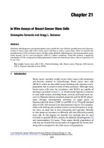
classes, each of which has an interface. If we relate these component classes to a composite class that also has an interface, and which is formed by taking a selection of methods from the interfaces of the component classes. This process of relating the interface of component classes to the interface of a composite class is known as method lifting. In the example below, the methods A, B & C are individually chosen from different component classes and combined in the composite class at the head of the hierarchy. This is shown below.
Fig. 1. An example of Method Lifting 3
Secondly, a particular class may have more than one lifeline. For example, a particular class may have many ports, each one with it’s own lifeline. This is invaluable in the case of modeling Agents since we need the facility to be able to represent an Agent in a sequence diagram, where it plays more than one role concurrently. You can see figure 2 for an example of this. The agent may be represented by a rectangle, and have many ports, each with it’s own lifeline. In the case of the method lifting paradiagm above the composite class may have many interfaces, each of which chooses a selection of methods from a hierarchy of component classes used as the source for method lifting. A sequence diagram where a composite classes that have more than one port is shown below in figure 2. Generally, communication between objects is done in UML in a sequence diagram, or a communication diagram (used to be called a collaboration diagram in UML 1.x). They are semantically similar although a sequence diagram can generally be made to contain additional information. A sequence diagram is generally defined across the page by a series of rectangles, each of which represents a class. Each of these rectangles has a dotted line running vertically down the page. These dotted lines are known as lifelines. As you go down the page, time passes as messages flow between objects.
4
D.S. Dillon, T.S. Dillon, and E. Chang
A sequence diagram where composite classes have more than one port is shown below in figure 2.
Fig. 2. Sequence diagram giving an example of a composite class with ports
In terms of previous work done using ports to represent an Agent/Class playing different roles Hanish & Dillon8 have previously used a similar and related approach. We now proceed to an illustrative example involving a set of Agents, one of which (Agreement Agent) plays two roles concurrently represented by P1 and P2. Depending on which role the agent is acting in when it sends/receives messages will the sequence diagram show arrows to/from a particular lifeline for the agent. The corresponding sequence diagram of a rental car being returned to a depot (for a car rental system) and payment being done by the customer is shown below. If we follow the sequence across and down the page, we note a number of points. Firstly, P1 (or port 1) represents the :Agreement agent in it’s role to establish status. P2 represents the :Agreement agent in it’s role to perform transactions. Note that each port has it’s own lifeline. If there are two ports, this signifies two roles that are played by the agent from which the ports come. Initially, the request is made to return a car. Secondly, the Agreement agent checks that the car is fine, and receives a message back that this is so. The same agent then performs a transaction to request the money owing on the car and the customer agent pays the money. Note that the Agreement agent plays two different roles here. Firstly, the role to check the status of the car, and secondly to perform the transaction. Then, the Agreement agent sets the status of the car to “free”, and receives a message back from the Vehicle agent that the car status is “free”. Again, the Agreement agent is acting in its role to compute status of the car. The Agreement agent makes a request to the Customer agent to set it to free. The Customer agent sets the status to free and returns the message to the
Using UML 2.1 to Model Multi-agent Systems
5
Fig. 3. Sequence Diagram illustrating Sociability of Agents
Agreement agent that the Customer is free. Finally, the Agreement agent sends a message to the Manager agent that the car is returned, and the Manager agent sends a message that the car is returned to the Employee. All the interaction between different Agents is shown on this sequence diagram. Importantly, an agent (Agreement) is shown playing two different roles on the same sequence diagram (Status and Transaction) in the same timeframe. 5.2 Goal-Driven Being goal driven is a feature of many different agents. In order to consider what this means we can reexamine the concept of search space. Forward-chaining begins with data which drives the reasoning toward goals. Backward-chaining goes backwards decomposing goals into subgoals and then checking to see if any of them is true. If so, the ultimate goal is considered to be true. If not, then the process of decomposition is continued. Most traditional software is not goal driven as such, but is a black box. That is, specific combinations of inputs lead to specific outputs. The fact that an agent has an overriding goal, regardless of the specifics of it’s processing, endows it with many other features. Specifically, it will be pro-active. ie. even if there are no events
6
D.S. Dillon, T.S. Dillon, and E. Chang
Fig. 4. Definition of stereotype
generated by human users that trigger the agent, it will take actions on it’s own to try and meet it’s goals. It will also be intelligent in trying to make use of it’s enviroment. For example, if the goal of the agent is to find certain data, it may migrate to another site once it has exhausted all possibilities at the current site. The decision to migrate may come from within the agent, rather than being triggered by an external event. In this case, we use the composite structure diagram, and extend it by using a stereotype in order to define the constructs necessary to define the goal-driven aspect of an Agent. The basic definition for a composite structure diagram in UML 2.1 is as follows.4 “A composite structure diagram is a diagram that shows the internal structure of a classifier, including its interaction points to other parts of the system. It shows the configuration and relationship of parts, that together, perform the behavior of the containing classifier. Class elements have been described in great detail in the section on class diagrams. This section describes the way classes can be displayed as composite elements exposing interfaces and containing ports and parts.” Below (in figure 4) is contained the definition of the stereotype based on the composite structure . diagram. From the definition it must have a name, at least a Manager part which controls the efforts of the Agent to achieve a goal, and at least one port, which relates to it’s playing a role. Having seen the definition of an stereotype we can proceed to an example to realize it’s usage. In the case of the Agreement agent in the Car Rental system, we can model the goal driven aspect of the agent by a Composite Structure Diagram with Parts, and Ports. Each part represents a distinct area of processing within the agent. Each port represents a different role played by the agent. The diagram encapsulating this information is shown in figure 5.
Using UML 2.1 to Model Multi-agent Systems
7
Fig. 5. Composite Structure Diagram representing Goal Driven characteristic of Agent
Note that the same two ports that were present in the sequence diagram are also present here. Each of the ports is a construct which enables the Agent to interact with the environment and with other Agents. For example, if the goal of the Agent is to close out processing with respect to a specific Rental Agreement, then the Agent will have to consult the Goal Driven part of the Agent to decide to check the car and the customer processing part of the Agent to finalize return and payment, and the goal driven part itself to see that the necessary checklist of items have been finalized for the return of the car.
6 Conclusion This paper has examined the use of UML 2.1 to model Multi-Agent Systems. In particular, we have examined and illustrated the Agent characteristics of being Sociable and also Goal-Driven. Specifically, in order to illustrate the fact that Agents are sociable we used a sequence diagram with ports. In order to illustrate the fact that Agents are goal-driven we used a composite structure diagram where the Agent is modeled with ports, which is new in UML 2. The use of ports is central where each port represents the Agent playing a different role. Future work may include the modeling of Agents to illustrate other characteristics of an Agent discussed in section 3. Acknowledgement. The authors would like to acknowledge the invaluable assistance and suggestions of Maja Hadzic as we authored this paper.
8
D.S. Dillon, T.S. Dillon, and E. Chang
References 1. Wooldridge, M.: An Introduction to MultiAgent Systems. John Wiley & Sons, Chichester (2002) 2. Hadzic, M.: Ontology-based Multi-agent Systems for Human Disease Knowledge Sharing. DEBII, Curtin University of Technology (July 2006) 3. Gardner, W.: Human Computer Interaction for Web Application. DEBII, Curtin University of Technology (August 2006) 4. PIlone, D.: UML 2.0 in a Nutshell. O’Reilly, Sebastopol (2005) 5. Bauer, Muller, Odell: Agent UML: A Formalism for Specifying Multiagent Interaction. In: Ciancarini, P., Wooldridge, M. (eds.) Agent-Oriented Software Engineering. Held at the 22nd International Conference on Software Engineering (ISCE), pp. 91–103. Springer, Berlin (2001) 6. Huhns,: Agent UML Notation for Multiagent System Design. Internet Computing 8(4), 63– 71 (2004) 7. OMG Group, OMG UML 2.1.2 Superstructure (02/11/2007) 8. Hanish, A.A., Dillon, T.S.: Object-oriented behaviour modelling for real-time design. In: IEEE Computer Society 3rd International Workshop on Object-Oriented Real-Time Dependable Systems (WORDS 1997), Newport Beach, California (1997)