Using UML to Develop Verifiable Reactive Systems Fatemeh Alavizadeh1, Marjan Sirjani1,2 1 ECE Dept., University of Tehran North Kargar, Tehran, Iran 2 School of Computer Science, IPM Niavaran Sq., Tehran, Iran
[email protected] [email protected]
Abstract Designing a correct model for distributed and reactive systems is the first goal of using Rebeca modeling language as an actor-based language supported by a formal verification tool. This paper proposes a method to perform formal verification of reactive systems at the early stages of the design cycle. We propose a UML profile for modeling systems consisting of reactive objects which are communicating via asynchronous messages and also a method for automatic code generation to Rebeca. In this way, developing verifiable models for this group of systems is made possible. This can bridge the gap between software development methods and formal verification by adding model checking step to software development life cycle.
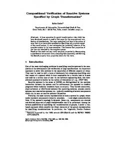
1. Introduction As traditional approaches to software engineering were no longer applicable to development of complicated and critical systems, new methods were introduced. In almost all of these methods modeling is the key to analysis and design. Visual modeling is helpful to keep the system more easily manageable. The Unified Modeling Language (UML) [7] was developed to respond to this demand and inspired a new approach to design: Model Driven Architecture (MDA) [25, 13, 14]. One of the most important aspects of MDA is code generation which is to automatically generate as much as possible code from the input model, leaving only little for the error-prone manual coding. The idea has many advantages such as reducing expenses spent on documentation, implementation and maintenance. Especially, implementation can be less expensive if the models are verifiable and executable, since errors are found early in the process [8]. To achieve these goals we introduce a UML profile for designing concurrent and distributed systems consisting of asynchronously communicating reactive objects. By converting these UML models to Rebeca [1, 2, 3, 4], verification can be done. Furthermore, there is a tool to convert Rebeca codes to Java, so Java code can also be generated [24]. As a result, there would be a path from UML model to Java code which supports verification via Rebeca and automatic code generation to Java. This can better be observed in Figure 1. Rebeca is an actor-based [9, 10] language for modeling and verification of reactive systems. The key features of Rebeca are: using actor-based concepts for the specification of reactive systems and their communications, providing a formal semantics for the model, providing a tool for model checking Rebeca code and using abstraction techniques to reduce the state space in model checking. One of the advantages of UML is its possibility of customization [7], because of large amount of concepts and complexity of UML, usually the usage of its concepts is restricted by defining UML profiles. A profile is a certain subset of the syntax of UML that specifies well-formedness rules beyond those in this subset, adds standard elements to the subset and specifies additional semantics in natural language. In other words, UML profile is a subset of UML concepts which is adequate to define our domain. To reach the mentioned goals, we introduce a new profile for UML by introducing new stereotypes. We use class diagram, object diagram, and sequence diagram to represent models. We also introduce a natural mapping to
generate Rebeca Code from these diagrams. Thus, we can get advantages of simplicity and unification of UML, as well as verification power of Rebeca.
Software Development
Formal Verification Model Design Errors Found
Code Generation
Model
Model Checking
Our path Executive Model Proof of Correctness Execution Figure1. The Proposed Method
2. Related works Related works cope both with the modeling of reactive systems using UML and the code generation process from UML diagrams. In the similar works for modeling reactive systems, usually state charts are used [12, 11, 14, 18]. In [12], in order to bridge the gap between system model and program code, state charts and SWITCHtechnology are used to develop reactive object oriented programs. In [11], a way for graphical design of reactive systems using state charts, is introduced which translates state charts into the Abstract Machine Notation (AMN) of the B method. In [14], a UML profile for development of distributed reactive systems is introduced which is also based on state charts. In [18], a new kind of formalized diagram is proposed to be used in design of reactive systems which is based on UML state charts. Many works have been done in order to generate code from UML diagrams. Tools like Rational Rose [27] support code generation from static diagrams to many target languages. In Together ControlCenter [26], Code generation is possible from static and dynamic diagrams [8]. On the other hand, some people have worked on generating code from user defined UML profiles, for instance, in [14] Ada code has been generated from the profile, and Mellor [17] defined a profile called xUML to generate executable code from state charts. Similarly, in this paper we introduce a new profile and the code generation process form the profile to Rebeca language.
3. UML and Rebeca The Unified Modeling Language, UML, is a general-purpose visual modeling language that is designed to specify, visualize, construct and document the artifacts of a software system [7]. UML is simple, powerful, and unified. First of all, UML is expandable; the core concepts can be combined and extended so that expert object modelers can define large and complex systems across a wide range of domains [7]. Moreover, UML is a standardized notation for modeling and documenting object-oriented software and business processes. The adoption of one single standard modeling language provides many benefits to software developers. Training is simplified since there is just one language to learn. It also simplifies the communication between development teams that now can exchange models using the common language. By introducing a new profile in UML, a reactive, distributed and concurrent system can be modeled using UML and formally verified using Rebeca Verifier [3], and also Rebeca developers can design their models with UML which makes it graphical, simple, more comprehensible, unified, standard, and easy to change and understand. Rebeca [4, 1], Reactive Objects Language, is an actor-based language for modeling and verifying concurrent and distributed systems. Rebeca is designed in an effort to bridge the gap between formal verification approaches and real applications. It is also a platform for developing object-based concurrent systems in practice. Rebeca is
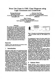
supported by Rebeca Verifier tool, as a front-end, to translate the codes into existing model-checker languages and thus, be able to verify their properties [2, 3]. In addition, Rebeca direct model checker is now under development [5, 6]. For a formal verification method, more than a model, there should be a specification language to embody correctness requirements. Here, temporal logic is used to specify safety and progress properties which are based on state variables of each rebec in the model [1]. Rebeca model is similar to the actor model in that it has independent active objects, and asynchronous message passing. These objects are reactive and self-contained. We call each of them a rebec, for reactive object. Computation takes place by message passing and execution of the corresponding methods of messages. Each message specifies a unique method to be executed when the message is serviced. Each rebec has a buffer, called a queue (or inbox), for arriving messages. When a message at the head of a queue of a rebec is serviced, its method is invoked and the message is deleted from the queue. Each rebec is instantiated from a reactive class, ‘reactiveclass’, and has a single thread of execution. We define a model, representing a set of rebecs, as a closed system. A Rebeca code is consisted of definition of reactive classes and a ‘main’ part. In the main part rebecs are instantiated from reactive classes. Each reactive class consists of known objects, state variables and a set of message servers. Known objects of a rebec, ‘knownobjects’, are those rebecs that this rebec can send them messages. All message servers, ‘msgsrv’, of a reactive class can use its state variables, but they are not public to be used by other reactive classes. The set of state variables identified by keyword ‘statevars’, are variables which represent the state of the rebec. It is required that every reactive class definition has at least one message server named ‘initial’ which is put in the queue when a rebec is instantiated. In declaring a rebec, the bindings to its known rebecs is specified in its parameter list. Figure 2, shows the constructs of a Rebeca model.
Figure2. Constructs of a Rebeca Model
4. UML Profile for Modeling Reactive Systems Since UML is customizable, we can introduce a new profile for modeling concurrent and distributed systems consisted of reactive objects which are communicating via asynchronous messages. In the modeling process, UML helps to represent our design with high level of abstraction. Since our development process is through Rebeca we need to show real world objects and their correspondent in Rebeca. Since Rebeca is an object-based language the mapping from UML diagrams to Rebeca models is natural. In the following we show how we can model reactive systems with UML and the mapping used to convert UML diagrams to Rebeca. Starting from the requirements the next step is to find the abstractions necessary to build the precise model of a domain by capturing the behavior of the parts it is comprised of. This model consists of a class diagram, an object diagram, and sequence diagrams. To describe the structure and behavior of the domain, it is necessary to search for entities which are alike and model them as classes. Then we shall find the properties necessary to describe such classes and the actions which can be done by these classes which will be modeled as the attributes and the methods of the class. Finally, the relationships between classes have to be established. The result of this process is a class diagram describing the structure of our system. In Rebeca, rebecs are the only entities constructing our systems, and reactive classes are used to make a template for the behavior of these rebecs. Naturally, objects are mapped to rebecs, and classes are mapped to reactive classes. To make this mapping standard we need to define a stereotype which in UML definition is a way to extend the vocabulary of UML, allowing us to create new kinds of building blocks that are derived from existing ones but that are specific to our problem [7, 8]. So a class, which has ‘reactiveclass’ stereotype, is a template for all reactive objects in our model. Attributes of a reactive object are state variables in Rebeca. There is a variation of UML in this step: in Rebeca visibility of all state variables is private, so we do not need to show visibilities in our model. As discussed above, we need to define a new stereotype which shows this mapping: ‘statevars’. Methods of a reactive
object are mapped to message servers in Rebeca. By defining a new stereotype, ‘msgsrv’ we can show the service of a reactive object which is invoked by sending an asynchronous message to that rebec. After identifying our entities we need to define relationships between these entities. In our context, we should specify the set of reactive objects that a specific rebec can send message to them as the set of known objects. We can represent message sending with an association between reactive class and its known objects. The mapping of Rebeca and UML to show the static structure of a reactive system by a class diagram is shown in Table 1. In the class diagram we can show other information such as the initial value of state variables. In Rebeca, initial message server is the first message server a rebec executes, so all initiations can be placed there. By assigning the initial value of state variables in our class diagram, we can show a part of the behavior of initial message server and consequently we can make the code of initial message server. An object diagram shows the instantiation and mapping of reactive classes to their known objects.
UML Element Class Attribute Method Association
Table1. Mapping between Rebeca and UML Constructs Rebeca Element Stereotype Reactive class reactiveclass State variable statevar Message server msgsrv Known object -
After describing the static structure, we should define dynamic behavior of our system. Using an interaction diagram you can model the behavior of a society of objects that work together. Both sequence diagrams and collaboration diagrams are kinds of interaction diagrams. They show an interaction, consisting of a set of objects and their relationships, including the messages that may be dispatched among them [7]. Interaction diagrams are known as “one story for all objects”. State machines describe the life-cycle of an object. A state machine is a behavior that specifies the sequences of states an object goes through during its lifetime in response to events, together with its responses to those events [7]. Sequence diagram is known as “all stories for one object”. Generally state machines are used to model reactive systems [12, 11, 14, 18]. Mellor [17] defined a profile called xUML to generate executable code from state charts which is a subset of UML on the one hand, and a superset with the additions of an action specification language on the other hand. The interesting part of xUML is that models created in this language can be compiled into any programming language and afterwards executed on any chosen platform [8]. On the other hand, some people have worked on generating code from interaction diagrams. An example is [19], the author introduces a way to map sequence diagrams to interaction graphs which deal with defining the scope of the variables included in the graph. This paper is a kind of aspect oriented programming supporting both forward engineering and reverse engineering. In [20], a way to enhance the semantics of collaboration diagrams beyond the standard of UML is presented. We also have chosen sequence diagrams in this profile. In the following some of the arguments leading to this decision are explained. State machines are used to show the behavior of objects which have a lifecycle that is of interest to be modeled, and it should be about lifecycles common to all instances of a class. However, in an abstract view, our reactive objects have fixed number of states and actions. The only observable action of a rebec is sending a message, and the only action affecting a rebec is taking a message from the top of the queue. Consequently, each rebec starts in ‘idle’ state and after receiving a message goes to ‘waiting’ state waiting for its turn, and then goes to ‘running’ state. Figure 3 shows this state chart. Although we can broke running state to sub states. Larman, in [15] encourages using state chart diagrams only for the purpose of illustrating external and temporal events and the reaction of an object to them. However, In Rebeca a message is unknown to a rebec till the rebec takes it out of the queue, and after that the rebec runs an atomic message server related to that message in which it can send messages to its known objects or change its state variables. So, dequeueing a message and executing an atomic message server cannot be considered as an external event. So, it is not a good idea to break the running state to sub states. Even if we try to show the state charts based on message servers and state variables, we cannot show as mush information about the design as we do now by use of sequence diagrams. Also code generation form sequence diagrams, in our case, is more viable. In addition, Harel argues that sequence diagrams are a medium for conveying requirements and state charts are part of the system model [16]. Since we want to perform formal verification in early stages of modeling, we prefer to use sequence diagrams as they can be extracted in a straight forward way from the domain. Therefore we chose interaction diagrams in our case, and among sequence diagram and collaboration diagram, sequence diagram is chosen, because it can better show the sequence of execution. Each sequence diagram shows a sequence of actions in a system. We can consider a system, a rebec, or each message server as an action unit and show it with one sequence
diagram. Considering a system as an action unit is very complicated. Considering a rebec as an action unit is also impractical, since we are trying to show the interaction between different objects rather than showing an object behavior. Also, we still can decrease complexity in defining dynamic behavior by considering a message server as an action unit. This is similar to what we usually do in software engineering: drawing a sequence diagram for each method. In our model, we draw a sequence diagram for each message server, and we show the sequence of actions invoked by receiving a message. In each sequence diagram we have one main rebec and its known objects (because they are the only possible message receivers); we also have a rebec known as “sender” which sends us the message. In each diagram the sequence of actions initiates by receiving a message from the sender, the rest of the diagram shows what would happen if the receiver rebec gets such a message, i.e., the code of the relevant message server. In our sequence diagrams, we can show messages which are sent by receiving a message. The UML standard has defined ways to notate conditional logic on sequence diagrams, using if-then-else structure we can show the dynamic structure more precisely. Also we can use “nondeterministic” condition for a call in a sequence diagram to make the model more comprehensible, although not many tools support these features. In the following example these explanations are illustrated.
5. Code generation The above discussions show how we can design concurrent and distributed systems consisting of reactive objects, in UML. If we model such systems with proposed profile, Rebeca code can be generated from the UML model. After that we can add other specifications of the system such as assignments or comments in generated code and make it a complete model, We can use Rebeca Verifier to model check the system either directly or indirectly (using Rebeca front-end model checker). We also can convert our model to Java for execution. To implement a tool to generate Rebeca code from UML models, we need to develop our diagrams in a case tool which supports the main features of UML that we need. Moreover, the tool must support XMI [21] as an intermediate representation. XMI is a widely used as interchange format for sharing objects using XML. Sharing objects in XML is a comprehensive solution that builds on sharing data with XML. XMI is applicable to a wide variety of objects including objects of UML diagrams. This representation contains all the information about the model that we need for code generation. XMI can convert graphical diagrams to XML. After that we can use XMI parser to gather information from the XMI document and build an abstract tree from XML. Rebeca code can be generated from this tree like the other Rebeca tools using a template engine that generates code from predefined templates. Using a template engine [22], we decouple the parsing of XMI document from the code generation step so that changes in the XMI parser do not affect code generation process [23].
6. Case study: Train-Controller We use the train-controller example to show our work. In a part of a two-way railroad is a bridge on which one train can pass at a time. There is a controller to control traffic signals. In our model we have a train and a controller reactive class. In the main part we instantiate two trains and a controller. Figures 4 and 5 show the static structure of the model in class and object diagrams. The main structure of the code can be generated from these diagrams. Dynamic behavior of the rebecs is shown in Figures 6, 7, 8, and 9. The Rebeca code generated from these diagrams is shown in Figure 10. The extra code that is added after code generation to complete the model is in bold.
Figure4. Class diagram for the Train-Controller Example
Figure5. Object diagram for the Train-Controller Example
Figure6. Behavior of Initial Msgsrv and Passed Msgsrv
Figure7. Behavior of YouMayPass Msgsrv and ReachBridge Msgsrv
Figure8. Behavior of Arrive Msgsrv
Figure9. Behavior of Leave Msgsrv
Figure10. The code generated from the model
7. Conclusion In this paper, we introduce a UML profile to represent distributed systems consisting of reactive objects communicating via asynchronous messages, and a method to generate Rebeca code from these models which can enable us to model check our systems in early stages of design process.
References [1]. [2]. [3]. [4]. [5]. [6]. [7]. [8]. [9]. [10]. [11]. [12].
[13]. [14].
[15]. [16]. [17]. [18]. [19]. [20].
[21]. [22]. [23]. [24]. [25]. [26]. [27].
M. Sirjani, A. Movaghar, A. Shali, F. de Boer “Modeling and Verification of Reactive Systems using Rebeca”, Fundam. Inform. 63(4): 385-410 (2004) M. Sirjani, A. Shali, M. Jaghoori, H. Iravanchi, A. Movaghar “A Front-End Tool for Automated Abstraction and Modular Verification of Actor-Based Models”, ACSD 2004: 145-150 M. Sirjani, A. Movaghar, A. Shali, F. de Boer “Model Checking, Automated Abstraction, and Compositional Verification of Rebeca Models”, J. UCS 11(6): 1054-1082 (2005) M. Sirjani, A. Movaghar, H. Iravanchi, M. Jaghoori, A. Shali “Model Checking in Rebeca”, PDPTA 2003: 1819-1822 M. Jaghoori, M. Sirjani, M. R. Mousavi, A. Movaghar “Efficient Symmetry Reduction for an Actor-Based Model”, ICDCIT 2005: 494-507 M. Jaghoori, A. Movaghar, M. Sirjani “The Model Checking Engine of Rebeca”, to appear in ACM SAC’06 G. Booch, J. Rumbaugh, I. Jacobson “The Unified Modeling Language User Guide”, Addison Wesley, October 1998, ISBN: 0-201-57168-4 M. Marinschek “Towards Executable UML - Code Generation From Interaction And State Chart Diagrams”, Master thesis, Technischen Universit¨at Wien, 2003 G. Agha, C. Hewitt “Concurrent Programming Using Actors”, in Yonezawa A., Tokoro M. Eds., ObjectOriented Programming, MIT Press, pp. 37-53, 1988 G. Agha “The Structure and Semantics of Actor Language”, in Proceedings of foundations of Object-Oriented Languages: REX School Workshop, Springer-Verlag, LNCS 489, pp. 1-59, 1991 E. Sekerinski “Graphical Design of Reactive Systems”, In D. Bert, editor, 2nd International B Conference, Lecture Notes in Computer Science Vol. 1393, Montpellier, France, 1998, Springer-Verlag V. S. Gurov, M. A. Mazin, A. S. Narvsky, A. A. Shalyto “UniMod: Method and Tool for Development of Reactive Object-Oriented Programs with Explicit States Emphasis”, IEEE BT02/C16/CE08/COM19/CAS04/ EM14 Societies Chapters’ SECTION Proceedings of St. Petersburg IEEE Chapters. 2005. V. 2, pp. 106-110 R. Soley, The OMG Staff Strategy Group “Model Driven Architecture”, Object Management Group, White Paper, Draft 3.2 – November 27, 2000 M. Kersten, J. Matthes, C. Fouda Manga, S. Zipser, H. Keller “Customizing UML for the development of distributed reactive systems and code generation to Ada 95”, Ada User Journal, Volume 23, Number 3, September 2002 C. Larman “Applying UML and Patterns: An Introduction to Object-Oriented Analysis and Design and the Unified Process”, Prentice Hall, 2002. D. Harel “From Play-In Scenarios to Code: An Achievable Dream”, 0018-9162/01/ 2001 IEEE S. J.Mellor, M. J. Balcar “Executable UML: A Foundation for Model-Driven Architecture”, Addison-Wesley, first edition, 2002. H. Feng “DCHARTS, A Formalism For Modeling And Simulation Based Design Of Reactive Software Systems”, Master thesis, McGill University, Canada, Feb 2004 N. Sangal, E. Farrell, K. Lieberherr “Interaction graphs: A system for specifying and generating object interactions”, Technical report, Tendril Software, Inc., 1998 G. Engels, R. ucking, St. Sauer, A.Wagner “UML collaboration diagrams and their transformation to Java”, In R. France and B. Rumpe, editors, UML ’99 - The UML - Beyond the Standard., pages 473–488. Springer, Berlin, October 28-30 1999. Second Intern. Conference. Fort Collins, CO. LNCS 1723 Object Management Group “XML Metadata Interchange Specification”, May 2005, Version 2.0 Velocity website. http://jakarta.apache.org/velocity/ K. Nguyen, Z. Sun, P. Thiagarajan, W. Wong “Model-driven SoC Design Via Executable UML to SystemC”, RTSS 2004: 459-468 http://khorshid.ece.ut.ac.ir/~rebeca http://www.omg.org/ www.borland.com/together/ www.ibm.com/software/rational