This article has been accepted for publication in a future issue of this journal, but has not been fully edited. Content may change prior to final publication.
11-1829-TIE
1
Vector Quantized Space Vector based Spread Spectrum Modulation Scheme for Multilevel Inverters using the principle of Oversampling ADC Biji Jacob, Member, IEEE, M. R. Baiju , Member, IEEE
Abstract— A generalized Space Vector based Spread Spectrum Modulation scheme for multilevel inverters is proposed in this paper. The proposed scheme uses the principle of sigma delta modulation as applied to analog-to-digital converters, based on the view that a multilevel converter could be interpreted as an oversampling analog-to-digital converter. The principle of Vector Quantization is utilized for quantizing the instantaneous reference voltage space vector in the proposed space vector based the sigma delta converter. The switching vectors of the inverter are naturally selected without sector identification, ensuring optimum switching sequence under all conditions including the over-modulation region. As the sigma delta converter results in a randomly varying switching frequency, the proposed scheme has spread spectrum characteristics. To avoid fractional arithmetic, sixty degree coordinate system is used to represent the space vector in this paper. The proposed scheme can be used for any general n-level inverter, and experimental results are presented for four-level, five-level and six-level inverters, driving 2-HP three phase induction motor in open-end winding configuration. Experimental results of the proposed scheme are compared with Space Vector PWM scheme and Random PWM scheme. Index Terms— Multilevel Inverter, Sigma Delta Converter, Space Vector, Spread Spectrum, Vector Quantization.
I. INTRODUCTION
F
OR the medium-voltage high-power industrial drive applications, multilevel inverters have emerged as an attractive choice. Speed control in adjustable speed drives are achieved by varying the duty ratio of inverter switches [1]–[4]. Multilevel inverters have improved total harmonic distortion and reduced stress on switching devices compared to two level inverters [2]–[7]. Commonly used modulation and control strategies in multilevel inverters are carrier based Sinusoidal Pulse Width Modulation (SPWM) and Space Vector PWM (SVPWM) [3]–[12]. Compared to carrier based pulse width modulation schemes, the space vector modulation schemes have better utilization of DC bus and are amenable to digital implementation [2]–[7]. Manuscript received on November 08, 2011. Accepted for publication May 11, 2012. Biji Jacob and M. R. Baiju are with the College of Engineering, Trivandrum, India (e-mail:
[email protected]) and (corresponding author phone:
[email protected]; fax: 91-471-2598370; e-mail:
[email protected]). Copyright (c) 2012 IEEE. Personal use of this material is permitted. However, permission to use this material for any other purposes must be obtained from the IEEE by sending a request to
[email protected].
The power spectrum of inverters using constant switching frequency PWM schemes is concentrated around the switching frequency and its harmonics [13]–[14]. This will result in acoustic noise, electromagnetic interference (EMI), copper loss, iron loss, overheating and torque pulsation in the electric machine driven by the inverters [14]. The random modulation schemes which produce spread spectrum characteristics can reduce these adverse effects [15]–[25]. The Random Pulse Width Modulation is obtained by comparison of reference signals with random number or by modulation of the switching frequency or by random variation of the position of the active switching vector [15]–[23]. In 3-level inverters, Random PWM is implemented by comparison of reference signal with random numbers and in space vector based Random PWM for 3-level inverter, randomness is achieved by realizing instantaneous reference voltage space vector among different possible combinations of inverter voltage space vector [24]– [25]. The multilevel inverters can be considered as oversampling analog-to-digital converters (ADC) which synthesize the low frequency analog reference input by switching the discrete inverter states at high frequency [26]–[28]. The oversampling ADC in signal processing applications use sigma delta modulator [29]–[30]. Delta modulation and sigma delta modulation have been proposed for resonant link inverters in motor drives [31]–[33]. Sigma delta modulation with scalar quantizer is used for power control of 2-level voltage source inverters [34]–[35]. The principle of vector quantization has been used in space vector modulation to realize spread spectrum characteristics for voltage source inverters [36]–[37]. For space vector modulation of multilevel inverters, the space vector diagram of the higher level inverter is decomposed into space vector diagrams of next lower inverters and further split into space vector diagram of 2-level inverters [37]–[40]. The present paper proposes a space vector based generalized random PWM scheme for multilevel inverters from the stand point of oversampling ADC. The reference space vector for any general n-level voltage space vector plane is mapped into the 2-level space vector plane directly in a single step for the modulation in this scheme. In the present work, spread spectrum technique using sigma delta modulator is applied to his mapped reference. The quantizer in the proposed sigma delta modulator is based on the principle of Vector Quantization. To eliminate fractional arithmetic, sixtydegree coordinate system is used for the representation of
Copyright (c) 2011 IEEE. Personal use is permitted. For any other purposes, permission must be obtained from the IEEE by emailing
[email protected].
This article has been accepted for publication in a future issue of this journal, but has not been fully edited. Content may change prior to final publication.
11-1829-TIE space vector in the present work. The switching vectors of the inverter are naturally selected ensuring optimum switching sequence under all conditions including the over-modulation region. The proposed scheme is implemented for four-level, five-level and six-level inverter topologies driving 2-HP three phase induction motor in the open-end winding configuration and experimental results are presented. II. THE PRINCIPLES ADOPTED IN THE PROPOSED SCHEME The proposed spread spectrum modulation scheme for multilevel inverters is evolved from two basic ideas. First one is that, the multilevel inverters can be viewed as oversampling ADC and hence techniques used with respect to oversampling ADCs are relevant in controlling multilevel inverters. Second idea is that at any sampling instance within the multilevel structure, only a 2-level structure is in operational as within any switching time period only three switches (one per phase) are operational. While the first idea is used in the present work to adopt sigma delta modulation based spread spectrum principles, the second idea is used to simplify the generation of SVPWM signals for the multilevel inverter. A. Multilevel inverter as Oversampling ADC The multilevel inverter has a discrete state output like a digital systems and it tries to approximate the input signal, which is a set of three phase analog signals, by switching its discrete states at a high frequency. Therefore, its behavior is similar to an analog to digital converter [26]–[28]. Since the input analog signals are sampled at a much higher frequency (the inverter switching frequency is much higher than the analog input), the inverters and hence multilevel inverters can be understood as a system of oversampling ADC [26]–[28]. This understanding prompts us to explore the possibility of adopting the techniques used in the context of oversampling ADC, to control multilevel inverters. In the case of a single bit oversampling type ADC, resolution that of 16 bit Nyquist rate ADC can be achieved by spreading the quantization noise out of the signal band width using sigma delta modulators [29]–[30]. The switching frequency in the sigma delta converters varies randomly resulting in spreading of output power spectrum. This will eliminate the concentration of energy at switching frequency harmonics which are present in the fixed frequency switching. In the present work, to spread the power spectrum of the multilevel inverters, the principles of sigma delta modulators are employed, similar to their application in the context of oversampling ADCs. The Space Vector based modulation scheme is used in the proposed scheme to generate the spread spectrum control signals for the multilevel inverters. B. Simplifying the Generation of Space Vector Modulation in Multilevel inverters In SVPWM scheme, the instantaneous reference voltage space vector is approximated by switching the three inverter voltage space vectors nearest to the tip of the reference voltage space vector [1]–[4]. The time duration for each of the inverter
2 voltage space vector depends on the amplitude and position of the instantaneous reference voltage space vector. The number of switching states for a three phase n-level inverter is n 3 , of which there are ( n − 1) 3 redundant states. The number of triangular sectors in the n-level inverter is 6 ( n − 1) 2 . Therefore, in the case of higher level inverters, the selection of inverter switching vector and calculation of the duration of these vectors become complex due to the availability of large number of inverter switching vectors [1]–[4]. The situation can be simplified if we closely examine the operation of the multilevel inverters at the individual switch level. In multilevel inverters, as in the case of a 2-level inverter, the state of the inverter changes from one state to another due to the switching of only one switch (which switches from one particular level to another). Within one sampling time period, the instantaneous reference sample is realized by switching three inverter states and hence three pairs of switches (one pair per phase) will be changing state, and all other switches retain their previous state. Taking these three pairs of switches together, it is like a 2-level structure operating within the multi level inverter. It is interesting to note that the switching pattern and PWM signals are similar to that of the 2-level inverter. That is, in each sampling time period only a 2-level inverter structure is in operation within the multilevel inverter structure. This is the motivation behind the mapping the instantaneous reference signal of the multilevel inverter to that of an equivalent 2-level inverter [38]–[40]. The switching vectors corresponding to the 2-level inverter and time periods can then be determined corresponding to the mapped reference voltage space vector using methods of SVPWM generation for a 2-level inverter. The switching vectors corresponding to the 2-level inverter can then be translated to switching vectors of the multilevel structure, maintaining optimum sequence [38]–[40]. III. THE PROPOSED SIGMA DELTA CONVERTER FOR MULTILEVEL STRUCTURE In the proposed scheme, 60 0 coordinate system is used for the representation of space vector instead of the conventional orthogonal coordinate system to reduce the computational complexity by eliminating fractional arithmetic [41]. As explained in the previous section, to simplify the switching scheme, the reference voltage space vector in multilevel inverter is mapped to 2-level inverter space vector plane. The space vector based sigma delta analogue-to-digital converter is used to convert the mapped analog reference voltage space vector to 2-level inverter switching states. The switching vectors generated in space vector based sigma delta converter corresponding to 2-level inverter are then translated back to the original multilevel inverter to obtain the actual switching vectors in multilevel inverter. In the proposed scheme, the switching vectors of the inverter are naturally selected to ensure the optimum switching sequence under all conditions including the over-modulation region. Hence a smooth transition is achieved from linear to over-modulation region.
Copyright (c) 2011 IEEE. Personal use is permitted. For any other purposes, permission must be obtained from the IEEE by emailing
[email protected].
This article has been accepted for publication in a future issue of this journal, but has not been fully edited. Content may change prior to final publication.
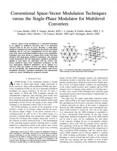
11-1829-TIE The steps involved in the proposed scheme are (A) Mapping of instantaneous reference voltage space vector to 2-level, (B) Generation of switching vectors using space vector based sigma delta converter and (C) Translation of switching vectors into multilevel topology, these are explained in detail in the following sections. A. Mapping of Instantaneous Reference Voltage Space Vector to 2-level The proposed spread spectrum modulation scheme can be used for any multilevel inverter topology. The proposed scheme is explained for a 6-level inverter. Fig. 1 shows the space vector diagram of a 6-level inverter. It may be noted that this space vector diagram is independent of the topology of the inverter. The different switching levels in a 6-level inverter are 0, 15 VDC , 52 VDC , 53 VDC , 54 VDC and VDC where VDC is the equivalent DC-link voltage of a 2-level inverter. These voltage levels in each phase are represented by 0, 1, 2, 3, 4 and 5 as seen in the space vector diagram and each vector location is a combination of these levels. In the case of a multilevel inverter, the same vector location can be realized by different combinations of these levels. For example, in Fig. 1 the vector at point D is realized by the vector 300. But it may be noted that the same vector location can also be represented by vectors 411 and 522. These are called redundant vectors. These redundant vectors are independent of the multilevel inverter topology. In Fig.1, the redundant vectors are not shown, to keep the diagram simple. In Fig.1 OR represents the instantaneous reference space vector. The space vector diagram of multilevel inverters can be considered to be composed of many 2-level space vector diagrams, called sub-hexagons [38]–[40]. The tip of the instantaneous reference space vector OR lies in the shaded space vector area of 2-level inverter named F. At different sampling instants the tip of the instantaneous reference space vector lies in different space vector area of 2-level inverter and
Fig. 1. Space Vector diagram of a 6-Level inverter and mapping of the reference voltage space vector into 2-level space vector plane.
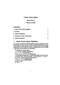
3 selects inverter voltage vectors corresponding to that active sub-hexagon. In Fig. 1, the sub-hexagon at the center (inner sub-hexagon-A) corresponds to the space-vector diagram of a 2-level inverter having the vector 000 as the center. These centers of the sub-hexagons are referred as the sub-hexagon center. The sub-hexagons named B, C, D, E and F also can be viewed as space vector diagrams of 2-level inverter having vectors 022, 030, 300, 204 and 440 respectively as its centers. It may be noted that, a particular sub-hexagon can be mapped to the inner most sub-hexagon, by subtracting the sub-hexagon center from the other six vectors of that sub-hexagon. The instantaneous reference voltage space vector which lies in a particular sub-hexagon can also be mapped to the inner most sub-hexagon by subtracting the sub-hexagon center from the instantaneous reference space vector [38]–[40]. In Fig. 1, the instantaneous the reference space vector OR will be mapped as OR’ in the inner sub-hexagon by subtracting the vector at the center of the sub-hexagon F (i.e. 440). Mapping the reference voltage space vector in multilevel inverter to the 2-level inverter space vector diagram simplifies the switching scheme of multilevel inverters. The calculation of the voltage vector switching time and the determination of switching sequence are done for the mapped reference voltage space vector in 2level inverter plane. The switching vectors generated for 2level inverter space vector plane is translated back to multilevel inverter space vector plane in a reverse approach to the mapping [38]–[40]. This translation of the 2-level vectors to the actual vectors of the multilevel inverter is achieved by adding the center of the sub-hexagon to the switching vectors generated in 2-level. This reverse mapping retains the time duration of the vectors and the optimality in the sequence. B. Space Vector based Sigma Delta Converter The proposed space vector based sigma delta converter scheme is used to generate the inverter switching vectors corresponding to the mapped reference voltage space vector. Fig.2 shows the proposed space vector based sigma delta converter scheme. The present paper proposes the structure consisting of two sigma delta converters each for the resolved m and n components in 60 0 coordinate system of the mapped
Fig. 2. Vector Quantized Space Vector based Sigma Delta Converter.
Copyright (c) 2011 IEEE. Personal use is permitted. For any other purposes, permission must be obtained from the IEEE by emailing
[email protected].
This article has been accepted for publication in a future issue of this journal, but has not been fully edited. Content may change prior to final publication.
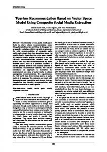
11-1829-TIE reference space vector. Each sigma delta converter consists of a difference node, a discrete time integrator, a space vector quantizer and a digital-to-analog converter (DAC) in the feedback path [29]–[30]. In the present work, the quantizer in the sigma delta converter uses the principle of Vector Quantization instead of conventional scalar quantizer [42]– [43]. The input to the integrator is the difference between the input signal V and the quantized output value S converted back to the predicted analog signal, Sa. This error is summed up in the integrator to produce integrated error vector Ve. It may be noted that the integrated error space vector Ve is random in nature, and it can be mapped to a point in a two dimensional vector space plane of 2-level inverter. This vector space can be divided into seven Voronoi regions, named A to G around each inverter voltage vectors (Fig. 3). Using the principles of Vector Quantization by which all the vectors in a Voronoi region are quantized to the corresponding inverter voltage vector. The eight inverter voltage vectors can be coded using 3 bits (000 to 111) which are the 2-level inverter voltage vectors. The algorithm to find out the Voronoi region and corresponding code vector are given in the flow chart in the shaded portion corresponding to the Space Vector Quantizer (Fig. 4). In the proposed scheme, the inverter voltage vectors are selected depending upon the Voronoi region of the instantaneous error vector and the sector of the input reference vector. Fig. 3 shows the Voronoi region of error vector Ve (regions A to G) and sectors of reference space vector V (sectors 1 to 6). The instantaneous switching vector is selected among the two active vectors corresponding to the sector and the zero vector to minimize inverter switching. A particular active vector is selected whenever the error vector falls in the respective Voronoi region ( ie the Voronoi region in which the active vector resides) or in the adjacent Voronoi region. Whenever the error vector falls in Voronoi regions other than the regions in which the two active switching vectors reside or
Fig. 3. The Voronoi regions A to G corresponding to the integrated error Ve and sectors 1 to 6 of reference space vector V.
4 in the regions adjacent to it, zero vectors are selected. The redundancy available in the case of zero vectors is exploited to ensure optimum switching sequence. Whenever the reference space vector crosses a sector, integrated error vector becomes large. If integrated error vector Ve is too large, selection of vectors from sectors that are not adjacent to reference space vector V are also possible. This results in direct polarity reversals in the inverter line to line voltages [33]–[34]. Such polarity reversals lead to increased over-voltage stresses at the load terminals. To overcome this, whenever vectors from non-adjacent sectors are selected, it is replaced by zero vector. To ensure the optimum switching sequence, zero vectors are selected depending on the sector in which the reference space vector lies. If the reference space vector V is in odd numbered sectors the gating pattern V7 = [1 1 1] and for the reference space vector V in even numbered sectors gating pattern V0 = [0 0 0] are selected. Hence the decision of switching vector depends on the reference space vector’s sector and the integrated error vector’s voronoi region. This will ensure minimum switching losses in the inverter. C. Generation of the Actual Switching Vectors of the Multilevel Inverter The switching vectors determined using the sigma delta modulator, are the switching vectors corresponding innermost sub-hexagon, onto which the actual sub-hexagon containing the tip of the instantaneous reference space vector was mapped. Now to generate the actual switching vectors of the multilevel inverter, i.e., the vectors corresponding to the original sub-hexagon containing the tip of the instantaneous
Fig. 4. Flow chart of the proposed algorithm.
Copyright (c) 2011 IEEE. Personal use is permitted. For any other purposes, permission must be obtained from the IEEE by emailing
[email protected].
This article has been accepted for publication in a future issue of this journal, but has not been fully edited. Content may change prior to final publication.
11-1829-TIE
5
reference space vector, the innermost sub-hexagon has to be reverse mapped to the actual sub-hexagon. This can be achieved by adding the vector value at the center of the selected sub-hexagon to the switching vectors of the 2-level inverter, resulting in the actual three switching vectors nearest to the tip of the instantaneous reference space vector [38]– [40]. The complete flow chart of the proposed algorithm is given in the flow chart Fig.4. IV. EXPERIMENTAL RESULTS AND DISCUSSION A.
The Power Circuit The proposed scheme for the n-level inverters can be applied to any inverter configuration viz., neutral point clamped, H-bridge, capacitor clamped and inverters with open-end-winding induction motor configuration. In the present work a power circuit, Fig.6, which can be configured
as 4-level, 5-level and 6-level multilevel inverter is used [44]– [49]. It consists of an open-end-winding induction motor fed with a 3-level inverter at one end and 2-level inverter on the connection of two conventional 2-level inverters [47]. The 4level, 5-level and 6-level inverter configurations can be achieved by different combinations of the dc-link voltages in the three inverters. Table I shows the dc-link voltages applied to the three inverters for the 4-level, 5-level and 6-level other side having asymmetrical dc-link voltages. The 3-level inverter configuration in the setup is realized by cascaded inverter configurations. The configuration is used to drive a 2 HP three phase open-end-winding induction motor with V/f control for different modulation indices covering different speed ranges. The scheme is implemented using the dSPACE DS 1104 RTI platform. The glue logic for realising the gating pulses from the PWM signals is implemented on Virtex-II PRO XC2VP30 FPGA board.
Fig.5. Open end winding induction motor driven by Multilevel inverter configuration realized by cascading conventional two 2-level inverters in one side and 2level inverter on the other side having asymmetrical dc-link voltage.
Fig.6(a). 4-level inverter pole voltages with modulation index m=0.8. Upper trace: Pole Voltage (VA2O) of cascaded inverter, Middle trace: Pole Voltage (VA3O’) of 2-level inverter and Lower trace: effective pole axis : voltage (VA2O – VA3O’). Scale : X-axis: 4 ms/div; Y-axis : 100 V/div.
Fig.6(b). 5-level inverter pole voltages with modulation index m=0.8. Upper trace: Pole Voltage (VA2O) of cascaded inverter, Middle trace: Pole Voltage (VA3O’) of 2-level inverter and Lower trace: effective pole voltage (VA2O – VA3O’). Scale :X-axis:4ms/div;Y-axis : (1)100V/div (2)50V/div.
Fig.6(c). 6-level inverter pole voltages with modulation index m=0.8. Upper trace: Pole Voltage (VA2O) of cascaded inverter, Middle trace: Pole Voltage (VA3O’) of 2-level inverter and Lower trace: effective pole voltage (VA2O – VA3O’). Scale : X-axis: 4 ms/div; Y-axis : 100 V/div.
Copyright (c) 2011 IEEE. Personal use is permitted. For any other purposes, permission must be obtained from the IEEE by emailing
[email protected].
This article has been accepted for publication in a future issue of this journal, but has not been fully edited. Content may change prior to final publication.
11-1829-TIE
6
Fig.7(a). 4-level inverter scheme with modulation index m=0.8. Upper trace: Motor phase voltage (VA2A3). Scale : X-axis: 4 ms/div; Y-axis : 50 V/div and Lower trace: Motor phase current (IA) Scale : Y- 1 A/div .
Fig.7(b) 5-level inverter scheme with modulation index m=0.8. Upper trace: Motor phase voltage (VA2A3). Scale : X-axis: 4 ms/div; Y-axis : 50 V/div and Lower trace: Motor phase current (IA) Scale : Y-axis : 1 A/div .
Fig.7(c). 6-level inverter scheme with modulation index m=0.8. Upper trace: Motor phase voltage (VA2A3). Scale : X-axis: 4 ms/div; Y-axis : 50 V/div and Lower trace: Motor phase current (IA) Scale : Y-axis : 2 A/div .
Fig.8(a). 4-level inverter scheme under over modulation condition. Upper trace: Pole Voltage (VA2O) of cascaded inverter, Middle trace: Pole Voltage (VA3O’) of 2-level inverter and Lower trace: Motor phase voltage (VA2A3). Scale : X-axis: 4 ms/div; Y-axis : 100 V/div for top and bottom trace and 50 V/div for middle trace.
Fig.8(b) 5-level inverter scheme under over modulation condition. Upper trace: Pole Voltage (VA2O) of cascaded inverter, Middle trace: Pole Voltage (VA3O’) of 2-level inverter and Lower trace: Motor phase voltage (VA2A3). Scale : X-axis: 4 ms/div; Y-axis : 100 V/div for top and bottom trace and 25 V/div for middle trace.
Fig.8(c). 6-level inverter scheme under over modulation condition. Upper trace: Pole Voltage (VA2O) of cascaded inverter, Middle trace: Pole Voltage (VA3O’) of 2-level inverter and Lower trace: Motor phase voltage (VA2A3). Scale : X-axis: 4 ms/div; Y-axis : 100 V/div for top and bottom trace and 50 V/div for middle trace.
Fig. 9(a). Experimental Three Pole Voltage (VA2O, VB2O, VC2O) waveforms for the proposed scheme with Three Level mode of operation (modulation index m= 0.8). Scale: X-axis: 4ms/div; Y-axis: 100 V/div. . Fig. 9(b). Time scale expanded waveforms of the 3 pole voltages of the marked region in Fig. (a). X-axis: 400µs/div; Y-axis : 100 V/div.
Fig.12. Experimental Results: Comparison of THD characteristics of the pole voltage for the Proposed scheme, SVPWM and Random PWM scheme.
Copyright (c) 2011 IEEE. Personal use is permitted. For any other purposes, permission must be obtained from the IEEE by emailing
[email protected].
This article has been accepted for publication in a future issue of this journal, but has not been fully edited. Content may change prior to final publication.
11-1829-TIE
7
Fig.10(a). Experimental pole voltage spectrum of 4level inverter for the proposed scheme with modulation index m=0.8. Scale : Y-axis : -40 ~ +40 dB, 10 dB/div; X-axis : 0 ~ 125 KHz, 12.5 KHz/div
Fig.10(b). Experimental pole voltage spectrum of 5-level inverter for the proposed scheme with modulation index m=0.8.Scale: Y-axis : -40 ~ +40 dB, 10 dB/div;X-axis:0 ~ 125 KHz, 12.5 KHz/div.
Fig.10(c). Experimental pole voltage spectrum of 6-level inverter for the proposed scheme with modulation index m=0.8. Scale : Y-axis : -40 ~ +40 dB, 10 dB/div;X-axis : 0 ~ 125 KHz, 12.5 KHz/div.
TABLE I DC-LINK VOLTAGE TO THREE INVERTERS AND NUMBER OF LEVELS Inverter-1 Inverter-2 Inverter-3 Number of Voltage Voltage Voltage Levels Obtained 1 3
V DC
1 4 2 5
1 3
V DC
Vdc
1 2
Vdc
2 5
1 3
V DC
4
Vdc
1 4
Vdc
5
Vdc
1 5
Vdc
6
B. Experimental Results of the Proposed Scheme Fig. 6 (a), (b) and (c) show pole voltages for 4-level, 5-level and 6-level inverters respectively. In Fig.6(a), pole voltages of 4-level inverter with modulation index m=0.8 are shown. Upper trace is the pole voltage (VA2O) of cascaded 3-level inverter and middle trace is the Pole Voltage (VA3O’) of 2-level inverter. The lower trace of Fig. 6(a) is the difference between pole voltages (VA2O – VA3O’) of 3-level and 2-level inverters driving the open-end winding induction motor. It shows the equivalent pole voltage of the open-end winding configuration and is similar to the 4-level pole voltage. Similarly, Fig. 6(b) and (c) are the pole voltages of the 5-level and 6-level inverter configurations. Lower traces of Fig. 6(b) and (c) show five and six levels in the equivalent pole voltage i.e. (VA2O – VA3O’) corresponding to the 5-level and 6-level inverter operation. The phase voltages and phase currents of the induction motor for 4-level, 5-level and 6-level inverter configurations are shown in Fig. 7(a), (b) and (c) respectively. The Fig. 7(a) shows four level mode of operation in the 4-level inverter with modulation index m=0.8. The five level mode of operation and six level mode of operation in 5-level and 6-level inverter with modulation index m=0.8 are shown in Fig. 7 (b) and (c) respectively. The pole voltage and phase voltage of the motor under the over-modulation condition are shown in Fig.8. In Fig. 8 (a), upper trace is the pole voltage (VA2O) of cascaded inverter and middle trace is the Pole Voltage (VA3O’) of 2-level inverter in the case of 4-level inverter configuration. The lower trace in Fig.8(a) shows the motor phase voltage (VA2A3) under overmodulation in 4-level inverter. In Fig. 8 (b) and (c) similarly
Fig.11(a). Experimental Phase voltage (VAO) spectrum for the proposed scheme with modulation index m=0.8. Scale : Y-axis : -40 ~ 40 dB, 10 dB/div; X-axis : 0 ~ 50 KHz, 5 KHz/div.
Fig.11(b). Experimental Phase voltage (VAO) spectrum for the SVPWM with modulation index m=0.8. Scale : Y-axis : -40 ~ 40 dB, 10 dB/div; X-axis : 0 ~ 50 KHz, 5 KHz/div.
show the pole and phase voltage under the over-modulation condition, in the case 5-level and 6-level inverters. Fig. 9 shows the time scale expanded waveform of the pole voltages of cascaded 3-level inverter and 2-level inverter in the 5-level inverter configuration. From time scale expanded waveform of the pole voltages shown in Fig. 9(b) it can be noted that the width of each pulse is constant which is equal to the sampling period. But the density of pulses varies there by
Copyright (c) 2011 IEEE. Personal use is permitted. For any other purposes, permission must be obtained from the IEEE by emailing
[email protected].
This article has been accepted for publication in a future issue of this journal, but has not been fully edited. Content may change prior to final publication.
11-1829-TIE
8
varying the effective width of pulses resulting in random variation of switching frequency. The random variation of switching frequency in the proposed scheme results in spreading of output spectrum as shown in Fig. 10. Fig. 10 (a) to 10 (c) show the spectrum of phase voltages obtained experimentally for 4-level, 5-level and 6-level inverter configurations respectively with modulation index m=0.8. The noise levels are less than 0dB in the proposed scheme at all frequencies and spread without any concentration at switching harmonics. The comparison of frequency spectrum of the proposed scheme with the SVPWM scheme at modulation index 0.8 is shown in Fig.11. For the SVPWM scheme in Fig. 11(b), it can be noted that clusters of switching noise are present at its switching frequency 5KHz and its harmonics. Fig. 12 shows the harmonic analysis and comparison of Total Harmonic Distortion (THD) characteristics of the proposed scheme, SVPWM scheme and Random PWM scheme. THD characteristics are evaluated experimentally with different modulation index for the Pole Voltage in the three schemes. It shows that Total Harmonic Distortion of the proposed scheme is much lesser than SVPWM scheme and comparable with the Random SVPWM scheme for all modulation indices.
[4]
[5]
[6]
[7]
[8]
[9]
[10]
[11]
[12]
V. CONCLUSION A generalized Spread Spectrum Modulation scheme for multilevel inverters is proposed, from the point of view that multilevel inverters are similar to oversampling ADCs. In the proposed scheme, the instantaneous reference space vector is mapped to an equivalent 2-level inverter and the proposed space vector based sigma delta modulation is applied on this mapped reference space vector. The resultant vectors of the 2level inverter can be easily translated to the actual switching vectors, and this proposed method of working on the mapped reference space vector makes the proposed scheme suitable for any general n-level inverter. The scheme uses the principle of Vector Quantization for quantizing the reference space vector in the sigma delta converter. The space vector region is divided into Voronoi regions and a method is proposed for the vector quantization of inverter switching vector. The proposed scheme is implemented for 4-level, 5-level and 6-level inverters driving a 2 HP three phase induction motor. The performance of the proposed scheme is compared with Space Vector PWM scheme and Random PWM schemes with different modulation index and experimental results are presented. REFERENCES [1]
[2]
[3]
L. M. Tolbert, F. Z. Peng, and T. G. Habetler, “Multilevel converters for large electric drives,” IEEE Trans. Ind. Appl., vol. 35, no. 1, pp. 36– 44, Jan./Feb. 1999. J. Rodriguez, J. S. Lai and F. Z. Peng, " Multilevel Inverters: A Survey of Topologies, Controls and Applications ", IEEE Trans. on Ind. Electron., vol.49, No.4, pp 724-738, Aug. 2002. J. Rodriguez, S. Bernet, Bin Wu, J. O. Pontt and S. Kouro " Multilevel Voltage-Source-Converter Topologies for Industrial Medium-Voltage
[13]
[14]
[15]
[16]
[17]
[18]
[19]
[20]
[21]
[22]
[23]
[24]
Drives", IEEE Trans. on Ind. Electron., Vol.54, No.6, pp 2930-2945, Dec. 2007 S. Kouro, M. Malinowski, K. Gopakumar, J. Pou, L. G. Franquelo, BinWu, J. Rodriguez, M. A. Pérez, and J. I. Leon, “Recent Advances and Industrial Applications of Multilevel Converters,” IEEE Trans. on Ind. Electron., Vol. 57, No.8, pp. 2553 – 2580, Aug. 2010. J. Rodriguez, S. Bernet, P. K. Steimer, and I. E. Lizama “A Survey on Neutral-Point-Clamped Inverters,” IEEE Trans. on Ind. Electron., Vol. 57, No. 7, pp. 2219 – 2230, July 2010. M. Malinowski, K. Gopakumar, J. Rodriguez, and M. A. Pérez, “A Survey on Cascaded Multilevel Inverters IEEE Trans. on Ind. Electron., Vol. 57, No. 7, pp. 2197 – 2206, July 2010. H. Abu-Rub, J. Holtz, J. Rodriguez, and Ge Baoming, “MediumVoltage Multilevel Converters—State of the Art, Challenges, and Requirements in Industrial Applications,” IEEE Trans. on Ind. Electron., Vol. 57, No. 8, pp. 2581 – 2595, Aug. 2010. P. Lezana, and R. Aceitón-“ Hybrid Multicell Converter: Topology and Modulation,” IEEE Trans. on Ind. Electron., Volume 58, Issue 9, Sept. 2011, pp. 3938 – 3945. J. Ebrahimi, E. Babaei, and G. B. Gharehpetian, “A New Multilevel Converter Topology With Reduced Number of Power Electronic Components,” IEEE Trans. on Ind. Electron., Volume 59, Issue 2, Feb. 2012, pp. 655– 667. Y. Zhang, Z. Zhao and J. Zhu “A Hybrid PWM Applied to High-Power Three-Level Inverter-Fed Induction-Motor Drives,” IEEE Trans. on Ind. Electron., Vol. 58, No. 8, pp. 3409 – 3420, Aug. 2011. A. Lewicki, Z. Krzeminski, and H. Abu-Rub, “Space-Vector Pulsewidth Modulation for Three-Level NPC Converter With the Neutral Point Voltage Control,” IEEE Trans. on Ind. Electron., Vol.58, No.11, pp. 5076-5086, Nov. 2011. S. Das and G. Narayanan, “Novel Switching Sequences for Space Vector Modulated Three-Level Inverters” IEEE Trans. on Ind. Electron., Volume 59, No. 3, pp. 1477–1487, March 2012. J.T. Boys and P.G. Handley, “Harmonic analysis of space vector modulated PWM waveforms,” IEE Proceedigs-B, Vol. 137, No. 4, pp. 197-204, 1990. J. W. Gray and F. J. Haydock, “Industrial power quality considerations when installing adjustable speed drive systems,” IEEE Trans. Ind. Appl., vol. 32, no. 3, pp. 646–652, May/June 1996. A. M. Trzynadlowski, S. Legowski and R. L. Kirlin, “Random Pulse Width Modulation Techniques for voltage-controlled power inverter,” Conf. Rec. 1987 IEEE-IAS Ann. Mtg., pp. 863–868. S. Legowski and A. M. Trzynadlowski, “Advanced Random Pulse Width Modulation Techniques for voltage-controlled inverter drive systems,” Proc. APEC’91, pp. 100–106. J.T. Boys and P.G. Handley, “Spread spectrum switching: low noise modulation technique for PWM inverter drives,” IEE Proceedigs-B, Vol. 139, No. 3, May 1992, pp. 252-260. A. M. Trzynadlowski, F. Blaabjerg, S. Legowski, “Random Pulse Width Modulation Techniques for Converter-Fed Drive System – A Review,” IEEE Trans. Ind. Appl., vol. 30, no. 5, pp. 1166–1175, Oct. 1994. T. G. Habetler and D.M. Divan, “Acoustic noise reduction in sinusoidal PWM drives using a randomly modulated carrier,” IEEE Trans. Power Electron., vol. 6, pp. 356–363, July 1991. A. R-Gonzalez, M. J. M-gutierrez, F. P-Hidalgo, F. V-Merino and J. R. H-Larrubia, “Reducing acoustic Noise Radiated by Inverter-Fed Induction Motors controlled by a New PWM Strategy”, IEEE Trans. on Ind. Electron., Vol. 57, No.1, Jan. 2010 pp. 228 - 235. A. M. Trzynadlowski, M. Zigliotto, and M. M. Bech, “Reduction of the electromagnetic interference conducted to mains in inverter-fed ac drives using random pulse-width modulation,” Proc. IEEE Industry Applications Soc. Annu. Meeting, 1998, pp. 739–744. R. L. Kirlin, C. Lascu, and A. M. Trzynadlowski, “Shaping the Noise Spectrum in Power Electronic Converters,” IEEE Trans. on Ind. Electron., Vol. 58, No.7, July 2011, pp. 2780 – 2788. L. Mathe, F. Lunguanu, J. K. Pedersen, “Spread spectrum modulation by using Asymmetric Carrier Random PWM” IEEE Trans. on Ind. Electron.,vol. 59, No.10, pp. 3710 – 3718, Oct. 2012. Y. Shrivastava and S. Y. Hui, “Analysis of random PWM switching methods for three-level power inverters,” IEEE Trans. Power Electron., Vol. 14, No.6, pp 1156–1163, Nov.1999.
Copyright (c) 2011 IEEE. Personal use is permitted. For any other purposes, permission must be obtained from the IEEE by emailing
[email protected].
This article has been accepted for publication in a future issue of this journal, but has not been fully edited. Content may change prior to final publication.
11-1829-TIE [25] C.K. Lee, S.Y.R. Hui, H.S.H. Chung, and Y. Shrivastava, “A randomized voltage vector switching scheme for Three-level power inverters”, IEEE Trans. Power Electron., Vol. 17, No. 1, Jan. 2002, pp. 94 – 100. [26] G. Luckjiff, I. Dobson and D. Diwan, “Interpolative Sigma Delta Modulators for High frequency Power Electronics Applications,” Proc. of Power Electronics Specialists Conference, PESC '95, vol.1, pp 444 - 449. [27] G. Luckjiff and I. Dobson, “Hexagonal Σ∆ modulators in Power Electronics,” IEEE Trans. Power Electron., Vol. 20, No.5 (Sep. 2005), pp1075 – 1083. [28] G. Luckjiff and I. Dobson, “Hexagonal Sigma Delta Modulation,” IEEE Transactions on Circuits and System I, Vol. 50, No.8 (Sep. 2003), pp991 – 1005. [29] R. M. Gray. “Oversampled Sigma-Delta Modulation,” IEEE Trans. on Communication, Vol.35, No. 5, May 1987, pp. 481 – 489. [30] P. M. Aziz, H. V. Sorensen, and J. V. Spiegel, “An Overview of SigmaDelta Convertors,” IEEE Signal Processing Magazine, Volume 13, Issue 1, September 1996, pp 61-84. [31] A. Boehringer and F. Brugger, “Transformatorlose transistor- pulsumrichter mit ausgangsleistungen bis 50 kva,”., E&M, vol. 96, no.12, pp. 538–545, 1979. [32] M. H. Kheraluwala and D. M. Divan, “Delta modulation strategies for resonant link inverters”, IEEE Transactions on Power Electronics, Vol.5, No.2, April 1990, pp. 220 – 228. [33] A. Mertens, “Performance analysis of three-phase inverters controlled by synchronous delta-modulation systems,” IEEE Trans. Indusry Applications, vol. 30, pp. 1016–1027, Aug. 1994. [34] J. Nieznanski, A. Wojewodka and P.J. Chrzan , “Comparison of Vector Sigma-Delta Modulation and Space-Vector PWM,” Conference of the Industrial Electronics Society IECON 2000 Volume 2, pp.1322 1327. [35] A. Hirota, S. Nagai and M. Nakaoka, “A Novel Delta-Sigma Modulated Space Vector Modulation Scheme using Scalar Delta-Sigma Modulator,” Proc. Power Electronics Specialists Conference, 2003, PESC ‘03, pp 485 – 489 vol.2. [36] B. Jacob and M.R. Baiju, “ Spread Spectrum Scheme for Two-Level Inverters using Space Vector Sigma-Delta Modulation,” Proc. 5th IET International Conference on Power Electronics, Machines and Drives, PEMD 2010. [37] B. Jacob and M.R. Baiju, “ Spread Spectrum Scheme for Three-Level Inverters based on Space Vector Sigma-Delta Modulation,” IEEE International Symposium on Industrial Electronics, ISIE 2010, July 2010, pp.1491-1496. [38] J. H. Seo, C. H. Choi and D. S. Hyun, “A New Simplified Space-Vector PWM Method for Three- Level Inverters,” IEEE Trans. on Power Electronics, Vol. 16, No.4, July 2001, pp 545–550. [39] A. K. Gupta and A. M. Khambadkone “A Space Vector PWM Scheme for Multilevel Inverters based on Two-level Space Vector PWM,” IEEE Trans. on Ind. Electron., Volume 53, No 5, Oct. 2006, pp. 1631 – 1639. [40] M. A. S. Aneesh, A. Gopinath and M.R. Baiju-“A Simple Space Vector PWM Generation Scheme for any General n-Level Inverter,” IEEE Trans. on Ind. Electron., Volume 56, Issue 5, May 2009, pp. 1649 – 1656. [41] N. Celanovic, and D. Boroyevich, “A fast space vector modulation algorithm for multilevel three phase converters,” IEEE Trans. on Industry Applications, Vol.37, No.2, 2001, pp637-641. [42] A. Gersho, “On the Structure of Vector Quantisation,” IEEE Trans. on Information Theory, IT-28 (March1982), pp157 –166. [43] R. M. Gray, “Vector Quantisation,” IEEE ASSP Magazine, April 1984, pp 4–28. [44] E.G. Shivakumar, K. Gopakumar, S.K. Sinha, V.T. Ranganathan, “Space vector PWM control of dual inverter fed open-end winding induction motor drive,” in Proc. IEEE Applied Power Electronics Conference and Exposition, APEC 2001, vol.1 , pp. 399 – 405. [45] Baiju, M.R.; Gopakumar, K., Mohapatra, K.K., Somasekhar, V.T., Umanand, L. “A five-level inverter voltage space phasor generation for an open-end winding induction motor drive”, IEE Proc.-Electr. Power Appl., Vol. 150, No. 5, September 2003 pp.531-538.
9 [46] M.R. Baiju, K.K. Mohapatra, R.S. Kanchan, K. Gopakumar. “A dual two-level inverter scheme with common mode voltage elimination for an induction motor drive,” IEEE Trans. Power Electron., vol. 19, No.3, pp. 794–805, 2004. [47] V. T. Somasekhar, K. Gopakumar, M. R. Baiju, K. K. Mohapatra, and L. Umanand, “A multilevel inverter system for an induction motor with open-end windings,” IEEE Trans. Ind. Electron., vol. 52, no. 3, pp. 824–836, Jun. 2005. [48] G. Mondal, K. Sivakumar, R. Ramchand, K. Gopakumar and E. Levi, “A Dual Seven-Level Inverter Supply for an Open-End Winding Induction Motor Drive," IEEE Trans. on Ind. Electron., vol. 56, no. 5, pp. 1665–1673, 2009. [49] B. V. Reddy, V. T. Somasekhar, and Y. Kalyan, “Decoupled SpaceVector PWM Strategies for a Four-Level Asymmetrical Open-End Winding Induction Motor Drive With Waveform Symmetries,” IEEE Trans. on Ind. Electron., Vol.58, No.11, Nov. 2011, pp. 5130-5141. Biji Jacob (M’10) received the B. Tech. degree in Electronics and Communication Engineering from College of Engineering Trivandrum, Kerala, India, in1988, and the M. Tech. degree in Electronics Design and Technology from the Center for Electronics Design and Technology, Indian Institute of Science, Bangalore, India, in 1998. From 1988 to 1991, he was with the National Airports Authority of India. Since 1991, he has been a member of the Faculty of the Department of Electronics and Communication Engineering, College of Engineering Trivandrum where he is currently an Associate Professor. His current research interest is motor drives. M. R. Baiju (M’98) received the B. Tech. degree in Electronics and Communication Engineering from College of Engineering Trivandrum, Kerala, India, in 1988, and the M. Tech. and Ph.D. degree from the Center for Electronics Design and Technology, Indian Institute of Science, Bangalore, India, in 1997 and 2004, respectively. From 1988 to 1991, he was with the National Thermal Power Corporation Ltd., New Delhi, India. Since 1991, he has been a member of the Faculty of College of Engineering Trivandrum where he is currently a Professor in the Department of Electronics and Communication Engineering. His areas of interest are inverter control strategies, MEMS and VLSI systems.
Copyright (c) 2011 IEEE. Personal use is permitted. For any other purposes, permission must be obtained from the IEEE by emailing
[email protected].