2006-01-1447
Verification and Validation of a Safety-Critical Steer-By-Wire System Using DO-178B Juan R. Pimentel Kettering University Copyright © 2005 SAE International
ABSTRACT The application of DO-178B for the verification and validation of the safety-critical aspects of a steer-by-wire sub-system of a vehicle by using a spiral development model is discussed. The project was performed within a capstone design course at Kettering University. Issues including lessons learned regarding requirements, specifications, testing, verification, and validation activities as required by DO-178B are summarized.
INTRODUCTION During the winter of 2004, as part of a capstone design course at Kettering University, two challenging projects were assigned to students taking this course. The first project involved the microcontroller design and implementation of a safety-critical steer-by-wire system and the second project involved the testing and verification of such system per the DO-178B standard. Projects 1 and 2 were performed by groups 1 and 2 comprised by 9 and 7 students respectively. Each group had a project leader/manager and its members were divided into smaller sub-groups during the duration of the project. All activities were carefully monitored by the group leaders and by the instructor. The schedule of the projects was tight as they had to fit during a school term at Kettering University (10 weeks not including final assessment). At the end of the term, both groups delivered what was required by the instructor and both projects were successful as they lead to a demonstration to SAE members on April 24, 2004 at Kettering University. This paper details the experience gained in applying the standard DO-178B for the testing, verification, and validation (V&V) of a steer-by-wire system in an academic environment. As the instructor for such course, the author did many activities prior to the beginning of the school term to document several items for the students including overview, purpose, scope, definitions, references, project organization, management process, system architecture development process, and expected deliverables. Prior to this course (spring of 2003), an earlier project on the microcontroller design and implementation of a safety-
critical steer-by-wire system using the S12 from Freescale and CAN drivers from Vector CANTech Inc. was undertaken. This project was not entirely successful as the software of the fault-tolerant aspects of the project proved too complex to manage. At around the same time the author developed a CAN-based communication architecture called FlexCAN, suitable for safety-critical applications by addressing fault-tolerant aspects [4]. Thus, students in the winter 2004 project benefited from the experience gained in the earlier projects. More specifically, they were given working versions of the following: FlexCAN protocol (implemented as a simulation in CANoe), CANoe simulator for the steer-by-wire system, locally developed S12 CAN drivers capable of using all five independent CAN channels on the S12. The projects for the winter of 2004 were basically to develop the software in C for the S12 microcontrollers, implement the software, and test and verify the software according to the DO-178B standard. The main concern of safety-critical and mission-critical systems is that they are developed thoughtfully and carefully with traceable evidence for every detail. Members of a development team should establish the “who, what, when, where, why, and how” in everything they do. This is accomplished by iterating through a simple four-step process in each stage of design and development. The steps, which are repeated over and over again, are: plan, execute, review, and report. This four-step process should be performed at every level of effort, from preparing the simplest component to the highest-level architectural specification. Planning includes entries in engineering notebooks, discussions with colleagues, meetings, and documented outlines of projected effort and responsibility. Execution means carrying out those plans. Review involves many activities including code inspections, design reviews, tests, verifications, analysis, and simulations. Finally, report means that you document the results of the three previous steps for immediate use in the next iteration. What it is being done is establishing and operating a quality system that aids the appropriate development of mission-critical and safety-critical systems. It will provide a complete audit trail. In the end, one should be able to demonstrate the “who, what, when,
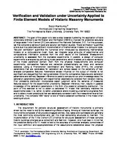
where, why, and how” of any development. Two wellknown standards for guiding the development of safety critical and mission critical software are the DO-178B [1] and the FDA “Design Control Guidance for Medical Device Manufacturers” March 11, 1997 [2], respectively. These standards give frameworks for development. They do not specify how each step is to occur. They tend towards guidance and use words and phrases like “represents current thinking on this topic” and “framework.” There are basically two models of development, similar in operation but different in the rigor applied to process and documentation. The first model is the prototyping model which basically iterates development until the customer is satisfied with the product. A second spiral development model, depicted in Fig. 1, iterates through four stages: requirements, analysis, design, and evaluation. The distance from the origin indicates the capability and completeness of the product. The prototyping model is appropriate in a research and development environment and for proof of concept. It easily accommodates changing requirements from the customer and makes a subset of the software available for early evaluation. Its disadvantage however is that both thorough testing and documentation are easily ignored and forgotten. The rush to completion also tends to leave out considerations for reliability, maintenance, and configuration control. The spiral approach to software development is more appropriate than prototyping for projects that need process control and traceability, such as safety-critical systems. This is so because the spiral development model is more formal incorporating explicit degrees of freedom which are fuzzy in the prototyping model. The spiral development model can accommodate changing requirements, but involves greater rigor in controlling the process.
CAPABILITY Analysis and feasibility
Design
chassis sub-systems. For example, DaimlerChrysler has a network validation process consisting of four levels that includes vehicle, system, sub-system, and component layers resulting in a 5-step CAN validation process involving software walkthrough, hardware testing, component level testing, sub-system functional validation, and system level network validation [3]. In this paper we discuss the application of DO-178B for the verification and validation of the safety-critical aspects of a steer-by-wire sub-system of a vehicle by using a spiral development model. The scope of the study was on V&V activities of just one sub-system (steer-by-wire). A vehicle may have other safety-critical sub-systems and the same V&V process has to be performed for each of these sub-systems. Although appropriate design and implementation tools were used (e.g., the IAR environment for software development and CANoe for CAN network development, no specific automated tools to perform V&V activities were used. The emphasis of the project was on performing V&V activities and not on developing the most efficient way of doing it.
THE DRIVE-BY-WIRE SYSTEM The steer-by-wire system is part of a golf-car at Kettering University. The system basically involves three components: the hand wheel (HW), a triplicated controller, and a road wheel (RW) on a duplicated CAN bus system as depicted in Fig. The hand wheel was a joystick that generated commands to the controller to turn the wheels to the right or to the left. The replicated controller took these commands and performed some safety and operational functions to generate reference signals for the actuators connected to the road wheel. The replicated controllers and duplicated CAN channels are features of FlexCAN, a fault-tolerant communication architecture suitable for safety-critical applications. All testing and verification activities were performed in a laboratory room. A single linear actuator was used in the actual golf car vehicle to effect turning of both wheels that were mechanically linked. The linear actuator was removed from the vehicle and integrated with the other components on a laboratory bench for testing.
COMPLETNESS
Requirements
Evaluation and Testing
Figure 1. Spiral development model. There are currently many V&V efforts at many companies for applications such as automotive body, powertrain, and
Fig. 2. Hardware layout of the steer-by-wire system.
All tests to support the V&V activities assumed the hardware configuration of Fig. 2 and the FlexCAN protocol timing diagram of Fig. 3.
Fig. 3. Timing diagram for the FlexCAN node replication algorithm. BACKGROUND, OVERVIEW, DESCRIPTION, AND EXPECTED DELIVERABLES OF THE PROJECTS
The complexity of contemporary automotive systems requires a disciplined systems approach for modeling, design, implementation, test, verification, and validation of automotive sub-systems. Issues such as test procedures, test cases, test coverage, and test results need to be considered. Design, implementation, testing, and verification will be conducted in strict conformance to the DO-178B standard. Fig. 4 depicts the system’s block diagram. As noted, the project for group I involves designing and implementing software for the steer-by-wire controller including the interfaces to the hand-wheel and roadwheels as depicted in Fig. 4. The project for group II involves testing and verification of all software involved in the steer-by-wire system.
Steering angle
Angle actuator
Steer-by-wire Controller
Hand wheel Wheel feedback
The projects started by having a general meeting with both groups where the background, overview, description, and expected deliverables of the projects were discussed and a document detailing these items were provided to the students. All printed information was also available on a specific course website. The students were then divided into two groups depending on their interest and experience. The following is an excerpt of the overall project objectives and description provided to the students at the first meeting.
Road wheel Actuator feedback
Dependable Controller Hwheel
ECU1
ECU2
Rwheel
CAN1
CAN2
Figure 4. Signal view and network view of the dependable, steer-by-wire system.
Objectives Detailed set of requirements and specifications Design, implement, test, and verify software for a highly dependable “steer-by-wire” system operating in a network environment (CAN). A hardware and software architecture and a simulation (in CANoe) of the steer-by-wire system already exist. Two groups will be formed, group I will work on the design and implementation portion while group II will work on the testing and verification portion. It is required that both groups will work very closely due to the testing and verification aspects of the project. The end result will be a sub-system that meets the stringent safety-critical requirements of DO-178B.
Both groups were then given a common detailed set of requirements classified as system requirements, hardware requirements, and software requirements. The system requirements pertained to the steer-by-wire system, the hardware requirements pertained to the specific microcontroller used (S12), and the software requirements pertained to the C-code to be developed to implement the functionality of the steer-by-wire system. These set of requirements were quite long thus only an excerpt of the requirements are listed below.
Project Description
Steer-by-wire system requirements
Modern products and processes are generally very complex with large electronic and software components. Some of these processes and products are said to be “safety-critical” because failure of some components may involve some risk either for machines (e.g., a vehicle) or humans. The project will primarily deal with two aspects of dependability: reliability and safety. The reliability aspect will be addressed by using redundant components to produce a “fault-tolerant” system. The safety aspect will be addressed by identifying “failure modes” and ensuring that the system exhibit safe behavior for a set of identified failure modes.
• • •
The controller will be designed to operate with 0, 1, or 2 replicated controllers(i.e., a total of 1, 2, or 3 ECUs) The system should exhibit safe behavior when any single of the system components fails. The system must handle the following failure modes: a) The road-wheels do not respond to a command from the hand-wheel. b) The road-wheels turn by themselves without any command from the driver c) There is no road feedback to the driver
Hardware requirements • • •
•
The system will use 2 CAN buses at 500 Kbps and 11-bit CAN identifiers Plug and play operation (i.e., controllers may be added or removed on the fly with no system disruption and in a safe manner. Modular components (system must operate with simulated or actual components). In particular, it should be possible that after all hardware controllers have failed, to insert a “simulated controller” using CANoe into the bus and regain control of the system. All hardware faults will be caused in a physical fashion (i.e., non of the hardware faults will be simulated)
Software requirements • • • • • •
Software must meet DO-178B specifications Software must meet MISRA-C specifications Modular code with extensive use of functions Scaleable code (i.e., easy to add replicated controllers, replicated channels, additional sensors, and additional actuators) All CAN message Ids should be identical to the corresponding Ids in the provided CANoe simulator. All software faults will be caused in the target system (i.e., none of the software faults will be simulated). For example if we want to see how the system reacts to a software error, specific software errors will be injected into the code by an appropriate software fault injection module.
THE DO-178B STANDARD The purpose of DO-178B is, “. . . to provide guidelines for the production of software for airborne systems and equipment that performs its intended function with a level of confidence in safety that complies with airworthiness requirements.” [1] . The scope is, “. . .those aspects of airworthiness certification that pertain to the production of software for airborne systems and equipment used on aircraft or engines.” The system and software life cycles are discussed as an aid for understanding the certification process. The document, “. . . does not provide guidelines concerning the structure of the applicant’s organization, the relationships between the applicant and its suppliers, or how the responsibilities are divided.” [1]. DO-178B recognizes that you can develop software in many different ways. It states, “This document recognizes that the guidelines herein are not mandated by law, but represent a consensus of the aviation community. It also recognizes that alternative methods to the methods described herein may be available to the applicant.” [1]. The following potential failure conditions are defined by DO-178B: Catastrophic, Hazardous/Severe-Major, Major, Minor, and No Effect. The level of the software is then defined according to its potential failure conditions: Level
A for potential Catastrophic failures, Level B for potential Hazardous/Severe-Major failures, Level C for potential Major failures, Level D for potential Minor failures, and Level E for potential No Effect failures. Defining your software accordingly will then affect what level processes you use. “DO-178B is primarily a process-oriented document. For each process, objectives are defined and a means of satisfying these objectives are described.” [1] The processes include: A. B. C. D. E. F. G. H. I. J.
Software Planning Software Development Verification of Outputs of Software Requirements Verification of Outputs of Software Design Verification of Outputs of Software Coding Verification of Outputs of Integration Verification of Process Results Software Configuration Management Software Quality Assurance Certification Liaison
The software for the steer-by-wire process was categorized as level B. This implies specific degrees of testing and verification as detailed in tables A-1 through A10 of DO-178B. However, the capstone design projects only dealt with process A through G above. A short description of how the projects handled processes A – G above follows. Software planning, one of the first processes handled by the students, involved identifying and interconnecting the various software components such as CAN drivers, timer drivers, sensor and actuator drivers, real-time executives, and functional (i.e., application) code. This process went smoothly due to the simple nature of the FlexCAN architecture and the availability of well tested modules such as the CAN, timer, sensor, and actuator drivers. Once the software planning process was finished, the software development process was relatively easy because of the modularity of the system with well defined interfaces. Students working on the various software components knew what to expect from the other modules and they also knew what outputs to generate for other modules. Processes C, D, and E involved designing appropriate test cases to verify the output of software taking three different viewpoints: software requirements, software testing, and software coding and integration respectively. For example, special test cases were created to verify the requirement of scaleable code in terms of replicated channels, controllers, sensors, and actuators. Process F is basically a verification of composabililty. Processes prior to process F ensure that the software components are verified independent from one another. Process F repeats the same tests on each component that now works together with the remaining components in an integrated fashion. Each process A through J also generate some results (e.g., design documents, review documents, software configuration documents) that also need to be verified by process G.
THE MISRA-C SPECIFICATION The primary language for implementation of embedded system functions is the C-language. Yet, it is well known that it is not a safe-language. Thus one has to be extremely careful when writing safety-critical code in C. To aid this function, the MISRA-C specification [5] has been published. It simply contains a list of rules some of them required while others are advisory in nature. Because of time-constraints, our project only considered a small subset of the MISRA-C rules.
DO-178B-BASED STEER-BY-WIRE TESTING, VERIFICATION, AND VALIDATION ACTIVITIES Because of the short timeframe of the project (10 weeks) and the spiral development model adopted, it was decided to have three major phases of software development resulting in three versions of the software. The three major phases were called initial, intermediate, and final with corresponding software versions A, B, and C respectively. These versions of software were frozen (i.e., no further development nor changes of any kind were allowed) at the 3repd, 6th, and 9th weeks into the project. All testing for V&V purposes were done with the frozen versions of the code (i.e., versions A, B, or C). One major advantage of this phased approach is that our tests were completely reproducible. No tests were performed on any other versions of the code. In between phases, group 2 members were busy performing backward testing and defining and documenting additional test cases to be performed at the next phase. By far, the most challenging activity was the creation, definition, execution and documentation of test cases. What criteria should be used to define test cases? Deciding on the criteria to be used is crucial as it determines the universe of discourse of the test space. For project 2 we used the following criteria to define test cases: A. B. C. D.
Avoidance of tight coupling Enforcement of assumptions of underlying technology Assurance of functionality (i.e., application) Adherence to appropriate standards
Tight coupling refers to errors propagating from one component to another. Research on safety-critical systems has shown that a major source of accidents are related to tight coupling [6], thus the appropriateness of this criterion. Underlying technology (in this case, FlexCAN) usually makes assumptions for optimum operation. For example, one failure model assumed by FlexCAN for controllers is fail-silent. Thus some tests must be designed to enforce assumptions of failure models. Criterion C helps design test cases to ensure that the software performs its intended function, in our case, steer-by-wire. Likewise, criterion D helps design test cases according to appropriate standards (in our
case DO-178B). For project 2, specific test cases were created in the following process categories: • • • • • •
Software Planning Software Development Verification of Outputs of Software Requirements Verification of Outputs of Software Design Verification of Outputs of Software Coding Verification of Outputs of Integration
The initial guidelines given to the students in terms of designing the test cases were to use the initial requirements provided by the instructor and applying methodologies such as FMEA (failure modes and effects analysis) and fault tree analysis. However, because members of group 2 were not intimately familiar with the FlexCAN architecture, and hardware and software components, several issues aroused. These issues were solved by a more direct involvement of the instructor (who was familiar with the FlexCAN architecture) and by having two students from group 1 help group 2 and also by having 2 students from group 2 participating in meetings of group 1. At the end of the final phase, we had good set of final test cases. The following is an excerpt of some of the test cases defined by group 2 to be used in the testing phase. 2.3.1.1 Primary Module Failure and Redundancy Test This test determines the effects of a Primary Module failure. Note the changes in the network messages sent on the network and by utilizing the trace window in CANoe to verify that the primary module has failed. Verify that one of the backup modules has taken over the functions of the primary. This is necessary for testing the redundant behavior of the system. 2.3.1.1.1 Procedure a) Locate the primary module. b) Disconnect the module power source. (See Figure 2.3.1.2). c) Using the trace window, look at the messages sent on the network and verify that the primary module has failed. d) Verify that another module has taken the functions of the primary (i.e. one of the backup module is elected/selected as primary). Reconnect the power to the primary module. (See Figure 2.3.1.2). e) Verify by looking at the messages on the trace window that the former primary has been reconnected and it has ranked itself according as one of the backup modules (i.e. back-up/tertiary etc.) without affecting the functions of the primary module.
2.3.1.2 Back-Up Module Failure This test determines the effects of a back-up module failure. Note the changes in the network messages sent on the network and by utilizing the trace window in CANoe to verify that the primary module has failed. Verify that one of the backup modules has taken over the functions of the primary. This is necessary for testing the redundant behavior of the system. 2.3.1.2.1 Procedure a) Locate the back-up module. b) Disconnect the module power source. (See Figure 2.3.1.2). c) Verify that the module has failed by using the trace window in CANoe by noting that the tertiary ECU will transmit a short time after the secondary should have d) Reconnect the power to the Back-up module. (See Figure 2.3.1.2). e) Verify that the module has identified by using the trace window in CANoe Note: The reconnected module should affect the ranking system and it should rank itself accordingly without affecting the functions of the primary module and should not come up as primary. f)
Repeat steps a) through f) as necessary for each back-up module.
2.3.1.3.1 Procedure a) Locate the primary module’s reset switch (See Figure 2.3.1.4.1) b) Press and release the reset switch c) Wait for a period of 2 seconds d) Press and release the reset again e) Observe the trace window in CANoe f) Note your observations Note: The module should be identified as failed every time it is disconnected and should rank its self appropriately when reconnected without affecting the functions of the system g) Repeat steps a) through f) approximately 13 more times, for an total of 15 resets NOTE: The number of resets is arbitrary and should be repeated as many times as possible for a statistically relevant assessment of the response.
2.3.1.4 Back-Up Module Flicker This test determines what happens if a back-up module on the bus turns on and off rapidly, and whether or not it affects any other modules. This test is to be performed on back-up modules. 2.3.1.4.1 Procedure a) Locate the back-up module’s reset switch (See Figure 2.3.1.4.1) b) Press and release the reset switch c) Wait for a period of 2 seconds d) Press and release the reset switch again e) Observe the trace window in CANoe f) Note any changes g) Repeat steps c) through e) approximately 13 more times, for an total of 15 resets NOTE: The number of resets is arbitrary and should be repeated as many times as possible for a statistically relevant assessment of the response.
Figure 2.3.1.2 Hardware schematic of module power
2.3.1.3 Primary Module Flicker This test determines what happens if the primary module on the bus turns on and off rapidly, and whether or not it affects any other modules. This test shall be performed on the primary module.
Reference Document: Capstone Design and Verification of a Safety Critical System Test Plan Date Performed: Procedure a) Locate the primary module
3/15/2004 Pass / Fail / NA
Comments
Pass
located Primary by observing trace window
b) Disconnect the module power source Pass c) Using the trace window look at the messages sent on the network and verify that the primary module has failed d) Verify that another module has taken the functions of the primary
Pass
messages stopped processing on ECU0
Pass
ECU1 took control
e) Reconnect the power to the primary module Pass
Figure 2.3.1.4.1 Reset Switch
f) Verify by looking at the messages on the trace window that the former primary has been reconnected and it has ranked itself according as one of the backup modules
Pass
ECU0 did not retake control. It was ranked correctly as a secondary ECU.
DISCUSSION
Figure 2.3.1.4.2 Reset switch schematic STEER-BY-WIRE TESTING VERIFICATION AND VALIDATION RESULTS As noted, the DO-178B standard requires a great deal of planning and documentation with traceable evidence for every detail. The appendix shows a system engineering plan and a project plan that was used for the projects. Whereas the system engineering plan is more generic and developed before the project begins, the project plan is more specific and iterated through the various phases of the project. The plans also provide a blueprint for generating appropriate reports and other documentation. Much emphasis was placed on a careful and thorough definition of test cases. Once the test cases were defined, reviewed, and validated, the actual testing was straightforward. However, for many tests, it actually took three iterations through software versions A, B, and C to arrive at a satisfactory test case definition. The following is an excerpt of test results corresponding to a test case previously defined in section 4. 2.3.1.1 Primary Module Failure and Redundancy Test
In this paper we have discussed the application of DO178B for the verification and validation of the safety-critical aspects of the steer-by-wire sub-system of a vehicle focusing on CAN communications. Several additional V&V activities on the other sub-systems and the entire vehicle needs to be performed for a complete V&V process. For example, additional tests to verify and validate the steer-by-wire system under a more complete set of requirements involving fail-operational and fail-safe requirements were not finished as part of the capstone design course. The particular set of students who participated in the projects did not have experience in software testing and verification activities. Although not major studies have been done, this author believes that more emphasis on software testing, verification, and validation is needed within the context of seminars, courses, and lectures at education and training institutions. Functional and behavioral system verification can be performed by using a modeling environment such as Simulink with tool chains from vendors such as Vector CANTech Inc., and dSPACE Inc. The tool needs several CAN interfaces because they need to be synchronized at small time frames (e.g., 0.1 ms). As noted, all of the tests were performed manually without the use of specialized automatic testing and verification tools. Verifying safetycritical software generated by an automatic code generation tool is a controversial issue. The main requirement is that all of the code generated by the tool needs to be verified each time the tool generates the software. If the process of automatic code verification could also be automated together with the code generation, then the issue would be resolved. Overall the project was successful in that both groups produced a working system with the deliverables required by the course. The working system was shortly after
demonstrated to a group of SAE members who were invited for a system demonstration. The success of the project were mostly due to the following: use of a simple communication architecture specifically designed for safety-critical applications (FlexCAN), the adoption of the spiral model, the splitting of students into two groups, a detailed set of system requirements and clear scope and expected deliverables, the naming of owners for each activities in each group resulting in individual as well as group responsibilities, working with only three frozen versions of the software, the use of and well proven underlying technology, and the use of appropriate tools. For non-safety critical systems, adopting appropriate V&V procedures from DO-178B into already existing procedures would be advantageous. However, for automotive safety critical systems a specific standard is highly needed that needs to incorporate hardware and software advances since the release of the DO-178B specification (December of 1992).
applicable to industry, caution must be exercised to transform the project from an academic environment to a company environment. All of the testing and verification activities were done manually because it was the first time experience with DO-178B.
It may appear that this paper contains excessive content on general information on how the projects were organized. However this is necessary as the project’s organization were intimately related to the following DO178B processes: • • • • •
Software Planning Software Development Verification of Outputs of Software Requirements Verification of Outputs of Integration Verification of Process Results
Thus, the project’s organization reflected many issues in the above processes.
REFERENCES 1.
“Software Considerations in Airborne Systems and Equipment Certification,” RTCA/DO-178B, December 1, 1992. RTCA, Inc., 1828 L Street, NW, Suite 805, Washington, D.C. 20036. You can purchase DO-178B at http://www.rtca.org.
2.
U.S. FDA “Design Control Guidance for Medical Device Manufacturers” March 11, 1997, relates to FDA 21 CFR 820.30 and sub-clause 4.4 of ISO9001. You can find it at http://www.fda.gov/cdrh/comp/designgd.pdf.
3.
S-T Min, Network Tool Usage in the DC Development Process, Vector Congress 2005, Troy, MI, Oct. 2005.
4.
J. R. Pimentel, An Architecture for a Safety-Critical Steer-by-Wire System, Paper No. 2004-01-0714, SAE Congress, Detroit, MI, Feb. 2004.
5.
"Guidelines for the Use of the C Language in Critical Systems", ISBN 0 9524156 2 3 (paperback), ISBN 0 9524156 4 X (PDF), October 2004, available at: www.misra.org.uk
6.
N. G., Leveson, Safeware: System Safety and Computers, Addison-Wesley, 1995.
SUMMARY AND CONCLUSIONS
CONTACT
There is a great deal of planning, reviewing, documentation, and testing involved in the design and development of a complete a safety-critical system. Having a good set of test cases is critical. The test cases have to be detailed, specifying the inputs, environmental conditions, tools used, procedures, and expected outcomes. Owners for the various activities and/or documentation is essential. This allows for accountability and improvement of deliverables. Most university students are not used to performing these kinds of activities. One major advantage of using the DO-178B standard in a project is that it will result in a well documented project, extremely useful for certification and the successful completion of similar projects in the future.
Dr. Juan R. Pimentel, Professor Department of Electrical and Computer Engineering Kettering University Flint, MI 48504 USA Email:
[email protected]
The most challenging things faced by students were: appropriate group organization, individual responsibilities and accountability, joint work, scope of verification activities, design of test cases, and thorough documentation. Although most of the experience and lessons learned in this academic experience are
Dr. Juan Pimentel is a Professor of Computer Engineering at Kettering University. He holds a Ph.D. degree in Electrical Engineering from the University of Virginia. Dr. Pimentel has done extensive research in the U.S, Germany, Spain, and Colombia. He is a Fulbright Scholar and an associate editor of the IEEE Transactions on Industrial Electronics and past Associate Editor of the IEEE Transactions on Mobile Computing. His main research areas are: distributed embedded systems, realtime networks and protocols, dependable systems, and safety-critical automotive networks, protocols, software, and applications. He is a member of Tau beta pi, Eta kappa nu, Sigma xi, IEEE, and SAE.
APPENDIX: SYSTEM AND PROJECT PLANS Systems Engineering Plan 1. Objective 2. Scope 3. Roles and Responsibilities 4. System Specification and Performance Verification 4.1. Requirements and Requirement Flow Down 4.2. Technical Performance Standards 4.3. Interface Definition and Control 4.4. Configuration Management and Change Tracking 4.5. System Validation 4.6. Performance Verification 4.7. Technical Performance Trending 4.8. System-Level Design Guidelines 5. Risk Management 5.1. Project Risk Management 5.2. Fault Tree Analysis (FTA) 5.3. Failure Modes and Effects Analysis (FMEA) 5.4. Margin Management 6. Independent Reviews 6.1. Peer Reviews Requirements 6.2. Formal Reviews 6.3. Action Item Management 7. Systems Engineering Documentation Project Plan 1. Introduction 1.1. Purpose 1.2. Scope 1.3. Definitions, Acronyms, and Abbreviations 1.4. References 1.5. Overview 2. Project Overview 2.1. Project Purpose, Scope, and Objectives 2.2. Assumptions and Constraints 2.3. Project Deliverables 2.4. Evolution of the Project Plan 3. Project Organization 3.1. Program Structure 3.2. Organizational Structures 3.3. External Interfaces and Organizations 3.4. Roles and Responsibilities 3.4.1. Program Manager 3.4.2. Systems Engineer 3.4.3. Hardware Engineering 3.4.4. Software Engineering 4. Management Process 4.1. Project Estimates 4.2. Project Plan 4.2.1. Phase Plan 4.2.2. Iteration Objectives 4.2.3. Releases 4.2.4. Project Schedule 4.2.5. Project Resources 4.3. Iteration Plans 4.4. Project Monitoring and Control 4.4.1. Requirements Management Plan
4.4.2. Schedule Control Plan System Architecture Development Process 5.1. Overview 5.2. Management and Staffing 5.3. Schedule and Iteration Plans 5.4. Design Inputs, Design Outputs, and Documents Required 5.5. Standards and Practices 5.6. Reviews 5.7. Test 5.8. Problem Reporting and Corrective Action 5.9. Tools, Techniques, and Methodologies 5.10. Configuration Management 5.11. Records Collection, Maintenance, and Retention 6. Software Development Process (6.1 – 6.11, same sections as System Architecture Development Plans) 7. Electronics Development Process (7.1 – 7.11, same sections as System Architecture Development Plans) 8. Mechanical Packaging Development Process (8.1 – 8.11, same sections as System Architecture Development Plans) 9. Glossary 10. Technical Appendices 5.