In this paper, a verification methodology of a com- position of UML behavioural diagrams (State Ma- chine, Activity Diagram, and Sequence Diagram) is.
Verification of the Correctness in Composed UML Behavioural Diagrams S. Ouchani1 and O. Ait Mohamed1 and M. Debbabi1 and M. Pourzandi2 1 Computer Security Laboratory, Concordia University, Montreal, Canada 2 Software Research, Ericsson Canada, Town of Mount-Royal, Canada Abstract— The Unified Modeling Language UML 2.0 plays a central role in modern software engineering, and it is considered as the de facto standard for modeling software architectures and designs. Todays systems are becoming more and more complex, and very difficult to deal with. The main difficulty arises from the different ways in modelling each component and the way they interact with each others. At this level of software modeling, providing methods and tools that allow early detection of errors is mandatory. In this paper, a verification methodology of a composition of UML behavioural diagrams (State Machine, Activity Diagram, and Sequence Diagram) is proposed. Our main contribution is the systematic construction of a semantic model based on a novel composition operator. This operator provides an elegant way to define the combination of different kind of UML diagrams. In addition, this operator posses a nice property which allows to handle the verification of large system efficiently. To demonstrate the effectiveness of our approach, a case study is presented. Keywords: Transition System, Unified Modelling Language (UML),Model Checking, Security Properties. I. I NTRODUCTION A major challenge in the software development process is to advance error detection to early phases of the software life-cycle. For this purpose, the verification of UML diagrams plays an important role in detecting flaws at the design level. It has a distinct importance for software security, since it is crucial to detect security flaws before they have been exploited. From the literature, a lot of techniques have been proposed for verification of softwares as well as hardwares like: Model Checking, Theorem Proving, and Static Analysis, etc. The most of the techniques used for verification of UML diagrams is model checking. Model checking is an important technology of automatic verification. It verifies the properties against a model through explicit state exploration, and elegantly presents the counter example paths when the system does not satisfy a property. The most important researches focusing on model checking of UML models verify the properties specified
by a formal language after extracting the semantic model of UML design, and then they translate it into the input languages of the existing model checkers. Most of the approaches proposed in the literature are intended either to activity, state machine [1, 3, 5, 6, 8, 9, 12, 14], or sequence diagrams [1, 13] separatly. We experience in industrial collaborations, that in practice most UML behavioural diagrams are mixed and connected. Effectively, in the literature there is a poor prior approachs that proposes a solution for this case when UML behavioural diagrams interacts. The main intent of our work is to focus on the verification of UML design models containing different connected UML behavioral models. We will focus on security properties like authentication. For that we have chosen the model checking technique because it’s automatic, and characterized by features like model reduction. To construct the semantic model of different UML behavioural diagrams, we defined a new compositional operator to fully automate the semantic model generation of the interacted UML models. The security properties are specified by a simple instantiation from security templates describing a set of applicationindependent properties to produce a set of applicationdependent properties proper to the application[5]. As a case study, we apply the proposed technique to verify the message authentication security property on Automated Teller Machine (ATM). ATM is written as an UML-based model composed of two different UML behavioural diagrams:a state machine describing client authentication and an activity diagram describing transaction operation. The ATM security properties were obtained from the authentication templates, and formalized by the formal language : the Computational Tree Logic (CTL)[2]. The result of this case study shows how to verify a complex system described by a mixed UML behavioural diagram. The remainder of this paper is organized as follows: Section II.presents the related work. Section III.explores UML behavioral diagrams (BDs) and their possible interactions inside a UML design. We define and generate the semantic model for the global UML design in the form of transition system in Section IV. . The proposed verification approach is detailed in Section V. . In Section
VI. , we provide a ATM case study. Finally, we conclude the paper by a conclusion and a promising future work in Section VII. . II. R ELATED W ORK In the state of the art, there is a considerable number of researches which are intended to verify just one kind of UML behavioural bediagrams like a state machine or a sequence diagram without taking in consideration their interactions when a state machine call an activity diagram for example. Cheng et al. [5] investigate how the verification of security properties can be enabled by adding formal constraints to UML-based security patterns. From the proposed templates, they instantiate the security properties to enable their analysis by using the Spin model checker. The limit of their work is in how to tailor a security pattern to meet the needs of a system especially when it contains a set of connected diagrams. A Static Verification Framework (SVF) is developped in [14] to support the design and verification of secure peer-to-peer applications. The framework supports the specification, modeling, and analysis of security properties together with the behavior of the system. The SVF developped in [12] is the continuation work of Andrea [14], they translate the UML state machine including guards into Promela models that are amenable for Spin model checking with LTL properties. Their works are limited to only the state machine diagram that describe a peer-to-peer applications, also their properties represents just a proposed scenarios for the attacker. Beato et al. [3] developed a complete automatic tool called TABU to transform active and state machine diagrams into an SMV (Symbolic Model Verifier) specification via Labeled Transition Systems (LTS). The properties are specified by the pattern classification proposed by Dwyer et al [7]. In their work, they didn’t consider when a state machines are composed with activity diagrams. Eshuis et al. describe in [8] a tool that verify UML activity diagrams by specifying the activity diagrams as a Clocked Transition Systems then generate automatically the NuSMV input code. The limits of their approach resides when they ignore the verification of some cases by stopping the computation of the transition system if one of the nodes becomes unbounded, and more than that, they focuse only on activity diagram. Giese et al. provide in [9] a domain specific formal semantic definition to verify a real-time UML design and an integrated sequence of design steps by prescribing how to compose complex software systems from domain-specific patterns. The composition of these patterns to describe the complete component behaviour is prescribed by a syntactic definition which guarantees the verification of components and system behaviour can ex-
ploit the results of the verification of individual patterns. Amstel et al.[13] propose trace analysis techniques by using model checkers to improve the quality of sequence diagrams, and to get PROMELA code from sequence diagrams. This technique provides a translation scheme that is defined in [11]. These works are limited to just one kind of real-time diagram as well as sequence diagram. Dong et al. in [6], define a set of rules to verify UML Dynamic Models. These rules are based on hierarchical automata between semantics structures, and simulation relation to reduce the detailed components to an abstracted specifications. In their work, they gave the results without linking their simple case study to the theory proposed. More than that, they didn’t mention the effect of the simulation relation in a model which is the main step in verification. In [1], a framework has been proposed for verifying UML diagrams, the extracted semantics model is called Configuration Transition System (CTS), a kind of Transition System. The resulting CTS is translated into NuSMV [10] code. This approach allows verfication behavioral against properties written in CTL, and our work is the continuation of [1]. The verification in [1, 3, 5, 6, 8, 9, 12, 13, 14] is done by using different semantic models, and using different checking techniques. None of them addressed the problem of linking several UML Behavioural Diagrams. III. S YNTAX
OF
UML B EHAVIORAL D IAGRAMS
UML supports behavioral modeling, but more than that it supports the interaction between behavioral models. Figure 1 shows the different UML behavioral models. In this section, we explore all the possible interactions between UML behavioral diagrams to complete the systax defined in [1]. A. State Machines (SM) In UML, we have two kinds of State Machines (SM): behavioral state machines and protocol state machines. The role of these two diagrams is to express the behavior of the system, and the usage protocol of part of that system, respectively. A SM can have association with a BD in its state as in its transition: • State: It models a situation where some invariant condition holds. A state can have one association with a BD in three places: 1. doActivity, a BD is executed while being in the state. The execution starts when this state is entered, and stops either by itself or when the state is exited whichever comes first. 2. Entry, a BD is executed whenever the state is entered regardless of the transition taken to reach the state. If defined, entry actions
• ObjectNode: It’s an abstract activity node that contains only values at runtime that conform to the type of the object node. It has an association with a BD in Selection to select tokens for outgoing edges. C. Interaction Diagram(ID)
Figure 1: all the possible interactions between UML behavioral diagrams.
Interactions are a mechanism for describing systems that can be understood and produced by providing different capabilities that makes it more appropriate for certain situations (i.e, Sequence Diagrams, Interaction Overview Diagrams, Communication Diagrams, Timing Diagrams and Interaction Tables). This kind of diagrams can have association with only one BD at time in a BehaviorExecutionSpecification element. It is a kind of ExecutionSpecification representing the execution of a behavior. A BehaviorExecutionSpecification can be associated with those BD having their execution occurring in a Behavior element. For the remainder of this paper we note Selmt as the set of elements where the BDs can be connected. IV. S EMANTIC OF UML B EHAVIORAL D IAGRAMS
are always executed to completion prior to any internal behavior or transitions performed within the state. 3. Exit, a BD is executed whenever this state is exited regardless of which transition was taken out of the state. If defined, exit actions are always executed to completion only after all internal activities and transition actions have completed execution. • Transition: It is a directed relationship between a source vertex and a target vertex in a state machine. During the activation of this transition, the behavioral diagram specified in association with Effect can be executed. B. Activity Diagram (AD) An activity diagram includes concurrent control, data flow, and decisions. It supports structured activities (sequences, loops, and conditions), but it can have just one association with another behavior at time for each of the following activity elements: • DecisionNode: It is a control node that chooses between outgoing flows. It has an association in decisionInput to provide input to guard specifications on edges outgoing from the decision node. • ObjectFlow: It is an activity edge to model the flow of values to/or from object nodes that can have objects or data passing along them. It can have two associations with a BD in Selection object to select tokens from a source object node, and in Transformation object to change or replace data tokens flowing along edge.
A. Configuration Transition System A Configuration Transition System (CTS)[1] is a formal description of the behavior of a system. A CTS is considered as a directed graph where nodes represent configurations, and edges model transitions. A Configuration is a specific binding of a set of values to the set of variables in the dynamic domain of the behavior of a system. i.e, the set of value assigned to the variables of the system during one step of execution (e.g., the evaluation of variables in an iteration of a program). A Transition specifies how the system can change from one configuration to another i.e, the relation between the current configuration and next ones. Definition 1 [1] gives the formal definition of a CTS. Definition 1 (Configuration Transition System). A Configuration Transition System CTS is a tuple (C, Act, →, I, E) where: • • • • •
C is a set of configurations, Act is a set of actions, →⊆ C × Act × C is a transition relation, I is the initial state, E is the final state.
Large systems are built from smaller parts, so we have to reason about their components, and how they interacts. Semantically, a component Πi of a system is represented by CT Si and the parallel composition of the system Π1 k . . . k Πn is represented by the composition of CTSs components CT S1 ◦ . . . ◦ CT Sn . In our case, the composition is defined as a simple substitution (Definition 2), we substitute the transition relation that represents an element of Selmt (called interface) by its corresponding CTS.
Definition 2 (Composition of CTS). Let CT Si , and CT Sj be two CTS where CT Si = (Ci , Acti , →i , Ii , Ei ), and CT Sj = (Cj , Actj , →j , Ij , Ej ). The composition (CT Si ◦ CT Sj ) of CT Si , and CT Sj is the substitution of CT Sj in the specific transition that represents the interface →r (ci1 , acti , ci2 ) of CT Si defined by the tuple: CT S = (S, Act, →, I, E), where: • • • • •
C = (Ci ∪ Cj ) \{Ij , Ej }, Act = (Acti ∪ Actj ) \{acti }, → ⊆ (→i ∪ →j ) \ →r , I = Ii , Ij = ci1 , Ej = ci2 , and E = Ei .
In order to ensure the scalability of the verification process for systems composed as Definition 1 we have derived Theorem 1. The proof is provided in the Appendix. Theorem 1. The composition of CTS’s is associative, i.e.: (CT Si ◦CT Sj )◦CT Sk = CT Si ◦(CT Sj ◦CT Sk ). More than that, we conclude from Definition 2 the maximum number of possibilties to apply the compositional operation in the initial CT S1 . This maximum is bounded by the number of interfaces and its up to the number of transitions (n). Also, we can observe that this composition is not commutative, and not transitive. B. Generation of Configuration Transition System To capture the semantic model of a single BD having no interaction with other BDs, we have to generate its proper CTS where each configuration represents the active elements in that diagram, and the transition represent the transition from source configuration to the target configuration. To achieve that, we iterate the breadth-first search procedure as presented in Algorithm 1 which is the simplified version of the one presented in [1]. In each iteration, the new configuration explored from the current configuration denoted by CurrentConf and the trace of configurations are saved in FoundConfList list where CTSTransList list contains the transitions between configurations. The unexplored configurations are in CTSConfList list, and EventList lists the possible incoming events. Initially, still they are a discovered configurations to explore in FoundConfList, the top element is loaded into CurrentConf and add it into result list of configuration if it’s not added in CTSConfList. Given the current configuration CurrentConf and the event list EventList, the trace of configuration FoundConfList is updated. While this trace is not empty the configuration transition list CTSTransList will be updated.
Algorithm 1: The CTS of a simple diagram CTS(FoundConfList ,CTSConfList, CTSTransList, EventList:list) begin while FoundConfList IsNotEmpty do CurrentConf = pop(FoundConfList); if CurrentConf not in CT SConf List then CTSConfList = CTSConfList ∪ {CurrentConf}; end NextTransList=getNext(CurrentConf,EventList); for nextTrans in NextTransList do nextConf = getDestination(nextTrans); FoundConfList = FoundConfList ∪ { nextConf }; end CTSTransList = CTSTransList ∪ NextTransList; end end To generate the CTS of a UML diagram interconnected with other BDs by association presented in section 2, and noted by →r in definition 2 we propose the recursive algorithm Algorithm 2 derived from Algorithm 1. The algorithm calls itself when a transition contains an interface. However, we avoid to recalculate the CTSs that have been already generated so far. V. V ERIFICATION M ETHODOLOGY Our contribution is an automatic model checking based approach as depicted in Figure 2. The approach consists of two parts: the verification part where we construct the global semantic model of our design model, and the second one is the Specification part where we express a set of security properties to be verified for our model. At the beginning of the verification part, we have a set of separated UML behavioral diagrams, for this reason we have to extract their corresponding semantic models (CTS) separately, and based on their interactions in the global model we construct its corresponding CTS by constructing the set of the existing interfaces between the CTSs of the small parts. The formal structure CTS representing the global system to be verified is a composition of a small ones: CT S1 , . . . , CT Sn where CT S = CT S1 ◦ . . . ◦ CT Sn . Our objectif is to check for a given property (π) if it holds for CT S verifying CT S |= π (i.e. CT S1 ◦ . . . ◦ CT Sn |= π) involves the exhaustive inspection of CT S instead of the property π. The property we want to verify should be formally specified by a b¨uchi automata, or using a temporal logic to be able to use model checking. Based on Definition 2,and Theorem1 we have derived a corollary to handle the verification of the complex system having n
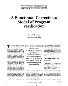
tional Tree Logic (CTL) for NUSMV1 model checker Algorithm 2: The CTS of a composition of dia[10] in our case. From the semantic model defined in grams section 1 we generate the appropriate NuSMV code to CTS(FoundConfList ,CTSConfList, be inputs to NuSMV model checker with the CTL exCTSTransList,EventList:list, d:diagram) pression of the instantiated security properties. begin while FoundConfList IsNotEmpty do CurrentConf = pop(FoundConfList); UML –based Security Properties Behavioral Templates if CurrentConf not in CT SConf List Diagrams then CTSConfList = CTSConfList ∪ { Composition of ApplicationCurrentConf }; UML –based independent Semantic Models Behavioral security properties end Diagrams NextTransList=getNext(CurrentConf,EventList); for nextTrans in NextTransList do ApplicationComposed dependent security if nextT rans HasInterface then Semantic Model properties if d not computed then CTS(F oundConf List,CT SConf List, CT ST ransList,EventList,d); Verification engine end end nextConf = getDestination(nextTrans) Figure 2: Compositional Verification Approach. FoundConfList = FoundConfList ∪ { nextConf }; As an example of this kind of specification, we picked end the template of message authentication presented in FigCTSTransList = CTSTransList ∪ ure 3 as a UML state machine where a countermeasure is NextTransList; taken if an authentication is failed. From this template, end we can extract the following security properties, and we end express them by a macro language, to be applied in the case study section. sub-components. The proof of Corollary 1 is pesented in the Appendix, and it is based on induction. Corollary 1. Let CT S = CT S1 ◦ . . . ◦ CT Si ◦ . . . ◦ CT Sn be a CTS composed of n-sub-CTS, and π a property, the following expression is always true: [(CT Si ◦. . .◦CT Sn ) |= π] ⇒ [CT S |= π] (1 ≤ i < n). From Corollary 1, we notice that in order to verify a property we don’t need to construct the whole semantic model of the system but only a subset. The main advantage of the Corollary 1 is to accelerate and optimize the verification procedure. The specification part: Our approach is a model checking based, so we have chosen to formalize our security properties by using a temporal language like (LTL, CTL, CTL*)[4] depending on the model checker used. For that, we are using a set of security templates proposed in [5]. Firstly, we extract the applicationindependent security properties from a given templates of security patterns like: Single Access Point, Check Point, Roles, Session, Full View with Errors, Limited View, Authorization, Multi-level Security. Secondly, we instantiate their appropriate application-dependent security properties and formalize them using temporal language of the adopted model checker such as Computa-
1. An unauthorized access leads eventually to the activation of a countermeasure. The corresponding property expressed in the macro language is the following: Always (UnautorizedAccess imply eventually (CounterMeasureTaken)) 2. When a request was denied, it is important that the current request remains unsuccessful until a new request is received. The corresponding property expressed in the macro language is the following: Always ((UnautorizedAccess imply Request Unseccessful) until NextRequest) 3. When an access is granted, then it should eventually be able to access the system successfully until the next request is received. The corresponding property expressed in the macro language is the following: Always ((AccessGranted imply eventually Operation) until NextRequest) Using the Graphviz 2 drawing tool, the CTS corresponding to the verified system, as well as the NuSMV assessment results (i.e., the counterexample), will be visualized graphically. 1 2
http://nusmv.irst.itc.it www.graphviz.org
[Forward Message]
Authentication passed
[Authentication data is valid according to ƚŚĞ�ƐLJƐƚĞŵ͛Ɛ� policies]
Authenticate
Waiting for request
Evaluate
[Countermeasure]
Authentication failed
[Authentication data is not valid according ƚŽ�ƚŚĞ�ƐLJƐƚĞŵ͛Ɛ� policies]
Figure 3: UML state machine template for the message authentication property. VI. C ASE S TUDY An Automated Teller Machine (ATM) is a system that interacts with a potential customer (user) via a specific interface and communicates with the bank over an appropriate communication link. A user that requests a service from the ATM has to insert an ATM card and enter a personal identification number (PIN). Both information need to be sent to the bank for validation, if the credentials of the customer are not valid, the card will be ejected out. These tasks of validation and ejecting are presented by an UML state machine diagram with effect (see Section III. ) as described in Figure 4. Otherwise, the customer will be able to
Figure 5: specifying the behavior of an ATM transaction.
Figure 6: The CTS corresponding to the State Machine of Figure 4. independent properties defined in Section V. , we instantiate their corresponding ATM dependent properties formulated with CTL as follow:
Figure 4: A state machine specifying the behavior of an ATM. perform one or more transactions where the card stays retained in the machine during the customer interaction until the customer wishes no further service. This part of transaction is described by the activity diagram depicted in Figure 5. To assess the composed diagram showed in Figure 4, we compose its CTS semantic models corresponding to state machine in Figure 6 and activity diagram in Figure 7 with the transition representing the interface of the effect as shown in Figure 8. From the message authentication template and their associated application-
1. A wrong Pin or Card leads automatically to ejecting the card. CTL: AG ((!CardV alid|!P IN V alid)) → EF (Eject) 2. A wrong Pin or Card remains an unsuccessful connection till a new request. CTL: A[EF [(!CardV alid|!P IN Invalid) → AX!OpenConnection]U Idle] 3. When both Card and Pin are valid, then it should eventually be able to make an operation until the next request is received. CTL: A[AG (CardV alid & P IN V alid ) → A[A[!OpenConnection U V erif yIdentity] U Eject] The operators used in the above properties are a mix of logical (!:Not, |:Or, &: And,→: Imply ), and temporal operators (A: All, E: Exists, X: neXt, G: Globaly, F:
by splitting the property and distributing sub-properties to the affected parts of the system to the end to achieve a conccurent verification, and develop a formalism proof rules to guaranty the satisfaction of the main property for the whole system. Secondly, The verification of the interacted diagrams must be done without changing their semantic models and verification tools if exists in the separate case in term to produce an optimal verification (cost/size of states). Even in this context, it’s very interesting to develop these perspective theory and applications for the industry as acadimia challenges. Figure 7: The CTS corresponding to the Activity Diagram of Figure 5. Finally, U: Until). To take advantage of the Corollary 1, we verify the following property: 4. AG(Init → EF (OpenConnection → EF (doOperation))) So without constructing the whole CTS, just by verifying the property in the CTS of the activity diagram we conclude that the first property is validated for the whole model. The verification of the above properties are done by the model checker NuSMV version 2.4.3 reveals the validation of the two first properties, and the fourth one. The violation of the third property as showed by the counterexample in Figure 8. The system diameter(minimum number of iterations of the NuSMV model to obtain all the reachable states) in the verification of each one of the properties is 10, and the number of reachable states is 36 out of 245760 and this is due to cone of influence algorithm implemented from second version of NuSMV and up. VII. C ONCLUSION In this paper we extended the formal verification from individual UML behavioural diagrams into more complex interactions between state machine, activity, and interaction UML behavioural diagrams. This approach allows verification engineer to detect flaws in the earlier stage of software cycle for more wide and complex systems. In fact this is what happens especially in industry where different diagrams interact together. In addition, our approach gives flexibility to write very expressive properties while hiding temporal operator. This technique, along with other verification tools, can provide a powerful and very useful framework to detect errors at the design phase, resulting in reliable software at the end of the software development process. As a future work, we target two main problems. Firstly, we intend to improve the verification approach in order to deal with more very large and more complex system
Figure 8: A counterexample for the third property
R EFERENCES [1] L. Alawneh, M. Debbabi, Y. Jarraya, A. Soeanu, and F. Hassayne. A unified approach for verification and validation of systems and software engineering models. In ECBS ’06: Proceedings of the 13th Annual IEEE Interntl. Symp. and Works. on Eng. of Comp. Based Sys., pages 409–418, Washington, DC, USA, 2006. IEEE Computer Society. [2] C. Baier and J. P. Katoen. Principles of Model Checking. MIT Press, New York, 2008. [3] M. E. Beato, M. Barrio-Solrzano, C. E. Cuesta, and P. de la Fuente. Uml automatic verification tool with formal methods. Electronic Notes in Theoretical Computer Science, 127(4):3 – 16, 2005. Proceedings of the Workshop on Visual Languages and Formal Methods (VLFM 2004). [4] B. B´erard, M. Bidoit, A. Finkel, F. Laroussinie, A. Petit, L. Petrucci, and Ph. Schnoebelen. Systems and Software Verification. Model-Checking Techniques and Tools. Springer, 2001. [5] B H. C. Cheng, S. Konrad, L. A. Campbell, and R. Wassermann. Using security patterns to model and analyze security. In In IEEE Workshop on Re-
[6]
[7]
[8]
[9]
[10]
[11]
[12]
[13]
[14]
quirements for High Assurance Systems, pages 13– 22, 2003. W. Dong, J. Wang, Z. Qi, and N. Rong. Compositional verification of uml dynamic models. In APSEC ’07: Proceedings of the 14th Asia-Pacific Soft. Eng. Conf., pages 286–293, Washington, DC, USA, 2007. IEEE Computer Society. M. B. Dwyer, G. S. Avrunin, and J. C. Corbett. Patterns in property specifications for finite-state verification. In ICSE ’99: Proc. of the 21st internatnl conf. on SE, pages 411–420, New York, NY, USA, 1999. ACM. Rik E. and Roel W. Tool support for verifying uml activity diagrams. IEEE Transactions on Software Engineering, 30, 2004. H. Giese, M. Tichy, S. Burmester, and S. Flake. Towards the compositional verification of realtime uml designs. SIGSOFT Softw. Eng. Notes, 28(5):38–47, 2003. Cimatti Clarke Giunchiglia, A. Cimatti, E. Clarke, F. Giunchiglia, and M. Roveri. Nusmv: a new symbolic model verifier. pages 495–499. Springer, 1999. S. Leue and P. B. Ladkin. Implementing and verifying msc specifications using promela/xspin. In Proceedings of the DIMACS Workshop SPIN96, pages 65–89, 1997. I. Siveroni, A. Zisman, and G. Spanoudakis. Property specification and static verification of uml models. In ARES ’08: Proceedings of the 2008 Third Interntl Conf. on Avail., Reliab. and Sec., pages 96–103, Washington, DC, USA, 2008. IEEE Computer Society. M. F. Van Amstel, Ch. F. J. Lange, and M. R. V. Chaudron. Four automated approaches to analyze the quality of uml sequence diagrams. In COMPSAC ’07: Proceedings of the 31st Annual International Computer Software and Applications Conference, pages 415–424, Washington, DC, USA, 2007. IEEE Computer Society. A. Zisman. A static verification framework for secure peer-to-peer applications. In ICIW ’07: Proceed. of the 2nd Internatnl Conf. on Internet and Web Applic. and Serv., page 8, Washington, DC, USA, 2007. IEEE Computer Society. A PPENDIX
Theorem. The composition of CTS’s is associative, i.e.,: (CT Si ◦ CT Sj ) ◦ CT Sk = CT Si ◦ (CT Sj ◦ CT Sk ). Proof. Consider three configuration transition systems CT Si , CT Sj , and CT Sk . CT Si compose CT Sj in the transition (called the interface) →r (ci1 , acti , ci2 ) where , and CT Sj compose CT Sk in a the transition →l (cj1 , actj , cj2 ). CT Si ◦ CT Sj = Γ (C1 , Act1 , →1 , I1 , E1 ) where:
• • • • •
C1 = (Ci ∪ Cj ) \{Ij , Ej }, Act1 = (Acti ∪ Actj ) \{acti }, →1 ⊆ (→i ∪ →j ) \ →r , I1 = Ii , Ij = ci1 , Ej = ci2 , and E1 = Ei .
And CT Sj ◦ CT Sk = Λ (C2 , Act2 , →2 , I2 , E2 ) where: • • • • •
C2 = (Cj ∪ Ck ) \{Ik , Ek }, Act2 = (Actj ∪ Actk ) \{actj }, →2 ⊆ (→j ∪ →k ) \ →l , I2 = Ij , Ik = cj1 , Ek = cj2 , and E2 = Ej . 0
From another side we have Σ = Γ ◦ CT Sk in 00 →l (cj1 , actj , cj2 ) and Σ = CT Si ◦ Λ in →r (ci1 , act� i , ci2 ), and by the same � composition we will 0 0 0 0 0 0 have Σ C , Act , → , I , E where: • • • • •
0
C = (C1 ∪ Ck ) \{Ik , Ek }, 0 Act = (Act1 ∪ Actk ) \{actj }, 0 → ⊆ (→1 ∪ →k ) \ →l , 0 I = Ii , 0 Ik = cj1 , Ek = cj2 , and E = Ei . � � 00 00 00 00 00 00 and Σ C , Act , → , I , E where: • • • • •
00
C = (Ci ∪ C2 ) \{I2 , E2 }, 00 Act = (Acti ∪ Act2 ) \{acti }, 00 → ⊆ (→i ∪ →2 ) \ →r , 00 I = Ii , 00 I2 = ci1 , E2 = ci2 , and E = Ei . 00
00
From the two previous result we find: Σ ≡ Σ , so the composition is associative up to isomorphisme. Corollary. Let CT S = CT S1 ◦. . .◦CT Si ◦. . .◦CT Sn a CTS composed of n-sub-CTS, and π a property, the following expression is always true: [(CT Si ◦ . . . ◦ CT Sn ) |= π] ⇒ [CT S |= π]. Proof. Here we will use the same formula and indications used in the previous proof to prove the first part. Let’s for a given property (π), and a global model CT S = CT S1 ◦ . . . ◦ CT Sn . Here we like to prove the following expression: [(CT Si ◦ . . . ◦ CT Sn ) |= π] ⇒ [CT S |= π] From the theorem1, we can write CT S = Γ ◦ Λ where: Γ = CT S1 ◦ . . . CT Si−1 , and, Λ = CT Si ◦. . .◦CT Sn . So we have to prove the following: (Λ |= π) ⇒ [(Γ ◦ Λ) |= π]. Consider π a sequence of states: π = (s0 , . . . , sn ) (Λ |= π) ⇔ (∃ ,→⊆→2 :,→≡ π). From the previous proof, we have →2 ⊆→ So, π ⊆→ which mean (Γ ◦ Λ) |= π. Finaly, CT S |= π.